group assignment: send a message between two
For this year’s group assignment, we will focus on the I2C protocol of communication.
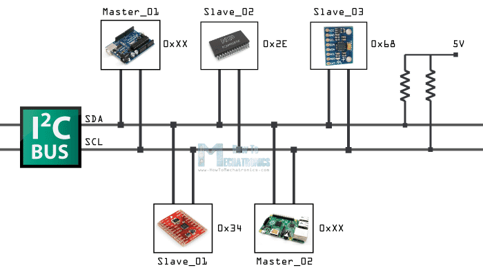
I2C (Inter-Integrated Circuit) is a widely used serial communication protocol that allows multiple devices to communicate with each other over a shared bus. It was developed by Philips Semiconductor (now NXP Semiconductors) in the early 1980s and has since become a standard for interconnecting integrated circuits.
The I2C protocol uses two wires for communication: a data line (SDA) and a clock line (SCL). These lines are bidirectional, allowing devices to both send and receive data. Each device on the bus is identified by a unique 7-bit or 10-bit address.
In I2C communication, one device acts as the master, which initiates and controls the data transfer, while the other devices act as slaves. The master device generates the clock signal and controls the timing of the data transfer.
The communication process involves two main operations: addressing and data transfer. To address a specific slave device, the master sends a start condition followed by the slave address. The addressed slave then responds with an acknowledgment (ACK) signal.
Data transfer can occur in two modes: write mode and read mode. In write mode, the master sends data to the slave by transmitting a series of bytes. The slave acknowledges each byte received. In read mode, the master requests data from the slave, which then transmits the requested data back to the master.
I2C supports multiple data transfer speeds, typically categorized into standard mode (up to 100 Kbps), fast mode (up to 400 Kbps), fast mode plus (up to 1 Mbps), and high-speed mode (up to 3.4 Mbps). These speeds can be adjusted based on the capabilities of the devices on the bus.
The I2C protocol offers several advantages, including simplicity, ease of use, and the ability to connect multiple devices using only two wires. It is commonly used for communication between various components in embedded systems, such as microcontrollers, sensors, actuators, and other peripheral devices.
In summary, I2C is a widely adopted communication protocol that provides a straightforward and efficient way for devices to exchange data, making it a popular choice for many applications in the embedded systems domain.

But before we start with the I2C, we need to get/know the addreses of the various devices. we will be talking about and using the I2C Scanner for this purpose.
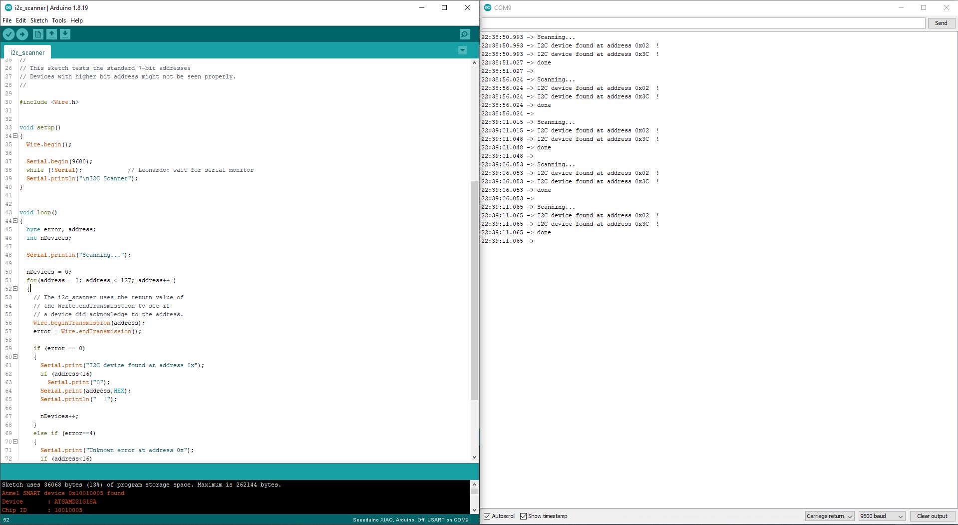
The I2C scanner is a simple program that can be executed on an Arduino to detect and identify I2C devices connected to the I2C bus. Here’s how it operates:
The code for the I2C scanner starts by including the Wire library, which provides the necessary functions for I2C communication. The setup function initializes the serial communication at a specified baud rate, and the loop function is where the I2C scanning process takes place.
In the loop function, the program iterates through all possible 7-bit I2C addresses (from 0 to 127) and sends a start condition followed by the address using the Wire library’s “beginTransmission” and “endTransmission” functions. If a device acknowledges the address, it means that a device is present at that address. The program then prints the address to the serial monitor, indicating the presence of an I2C device.
The I2C scanner code is a useful tool for identifying I2C devices connected to an Arduino. It helps verify the correct connection of devices and their assigned addresses. By examining the output on the serial monitor, you can determine the I2C addresses of the connected devices and use them in your further programming and communication tasks with those devices.
Primary & Secondary Boards
After finding the addresses we will now have a Master(primary) board and a Slave(secondary).
Primary
In I2C (Inter-Integrated Circuit) communication, the primary device is the one that initiates and controls the communication on the bus. It generates the clock signal, addresses the Slave devices, and controls the data transfer.
Secondary
On the other hand, the Slave devices are the peripherals or components that respond to the commands or requests from the Master. They wait for instructions from the Master and provide data or perform actions accordingly.
Now the operation of I2C is based on Primary-Secondary (master-slave) communication. The microcontroller acts as a master, controlling data flow to attached secondary (slave) devices. Each secondary (slave) device has a unique address assigned, allowing the primary (master) to select which device it wishes to communicate with.
When I2C communication is initiated, the primary (master) sends a start signal, followed by the address of the secondary (slave) device it wishes to query. Then the data is transmitted, usually in bytes, between the primary (master) and the secondary (slave). The primary (master) generates clock signals to synchronize the transmission.
Codes
Master
//#Primary I2C

#include <SPI.h>
#include <Wire.h>
#include <Adafruit_GFX.h>
#include <Adafruit_SSD1306.h>

#include <Servo.h>

Servo myservo;  // create servo object to control a servo
// twelve servo objects can be created on most boards

int pos = 0;    // variable to store the servo position

int buz = 0;    // variable to store the servo position
#define SCREEN_WIDTH 128 // OLED display width, in pixels
#define SCREEN_HEIGHT 32 // OLED display height, in pixels
#define OLED_RESET     -1 // Reset pin # (or -1 if sharing Arduino reset pin)
#define SCREEN_ADDRESS 0x3C ///< See datasheet for Address; 0x3D for 128x64, 0x3C for 128x32
Adafruit_SSD1306 display(SCREEN_WIDTH, SCREEN_HEIGHT, &Wire, OLED_RESET);


#define servoPin D3
#define buzzerPin D6

void setup() {
  myservo.attach(servoPin);  // attaches the servo on pin D3 to the servo object

  // initialise les broches du Buzzer
  pinMode(buzzerPin, OUTPUT);
  Wire.begin(); // join i2c bus (address optional for master)
  Serial.begin(9600);

  // SSD1306_SWITCHCAPVCC = generate display voltage from 3.3V internally
  if (!display.begin(SSD1306_SWITCHCAPVCC, SCREEN_ADDRESS)) {
    Serial.println(F("SSD1306 allocation failed"));
    for (;;); // Don't proceed, loop forever
  }

  display.display();
  delay(1000); // Pause for 2 seconds

  // Clear the buffer
  display.clearDisplay();
}

void loop() {
  byte temperature;
  Wire.requestFrom(2, 1); // Request temperature data from secondary  at 2
  if (Wire.available()) {
    temperature = Wire.read(); // Read temperature data from secondary
    Serial.print("Temperature from secondary : ");
    Serial.print(temperature);
    Serial.println(" C");
  }

  display.clearDisplay();
  display.setTextSize(2); // Draw 2X-scale text
  display.setTextColor(SSD1306_WHITE);
  display.setCursor(0, 0);


  buz = map(temperature, 0, 100, 100, 1000);
  pos = map(temperature, 25, 50, 0, 180);
  myservo.write(pos);              // tell servo to go to mapped position in variable 'pos'
  delay(15);

//  display.print(F("Hr: "));
//  display.print(h);
//  display.println(F("%"));
  display.print(F("T: "));
  display.print(temperature);
  display.println(F("C"));
  display.display();
  delay (1000);
  display.clearDisplay();

  Serial.print(F("buz: "));
  Serial.println(buz);
  Serial.print(F("Angle: "));
  Serial.println(pos);

//  Serial.print(F("Humidity: "));
//  Serial.print(h);
//  Serial.print(F("%  Temperature: "));
//  Serial.print(t);
//  Serial.println(F("°C "));

  alarm();

}

void alarm() {
  tone (buzzerPin, buz); // allume le buzzer actif arduino
  delay(500);
  tone(buzzerPin, buz); // allume le buzzer actif arduino
  delay(500);
  noTone(buzzerPin);  // désactiver le buzzer actif arduino
  delay(500);
}
Secondary
//#Secondary I2C

#include <Wire.h>
#include "DHT.h"

#define DHTPIN D3
#define DHTTYPE DHT22   // DHT 22  (AM2302), AM2321

DHT dht(DHTPIN, DHTTYPE);

byte temperatureC;
byte humidity;

void setup()
{

  Serial.begin(9600);
  dht.begin();
  Wire.begin(2);                // join i2c bus with address #0x02 (OLED Screen is already On 0x3C)
  Wire.onRequest(requestEvent); // register event

}

void loop()
{
  humidity = dht.readHumidity();
  // Read temperature as Celsius (the default)
  temperatureC = dht.readTemperature();

  Serial.print(F("Humidity: "));
  Serial.print(humidity);
  Serial.print(F("%  Temperature: "));
  Serial.print(temperatureC);
  Serial.println(F("°C "));

  delay(500);
}

// function that executes whenever data is requested by master
// this function is registered as an event, in the setup()
void requestEvent() {
  Wire.write(temperatureC);
}
For the explanation for the various codes, visit Ousia’s Page. He is the author of the codes.