Output Devices that we measured the power consumption of:
DC motor
RGB LED
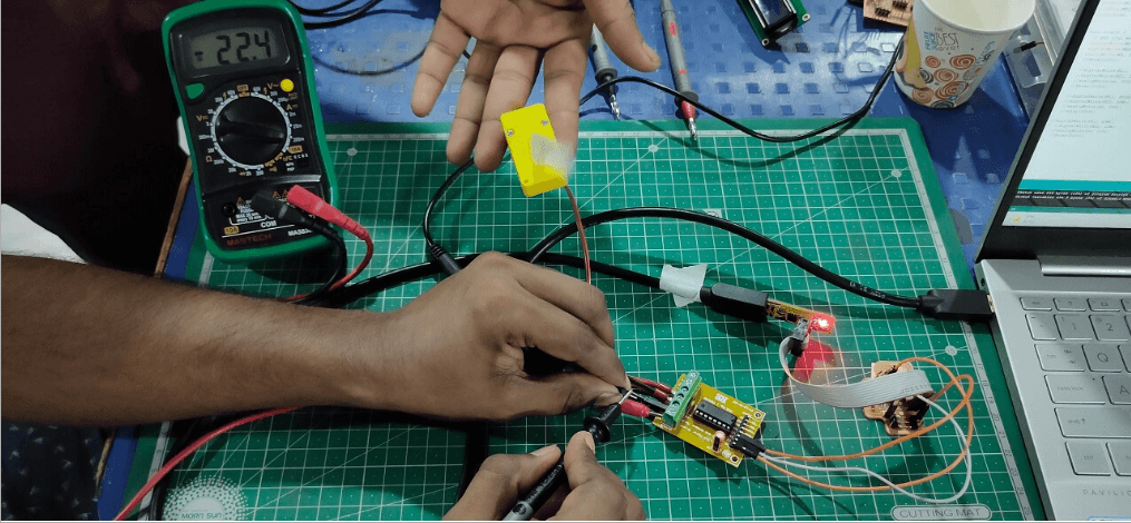
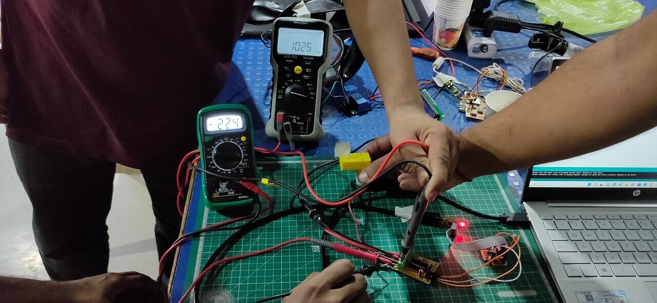
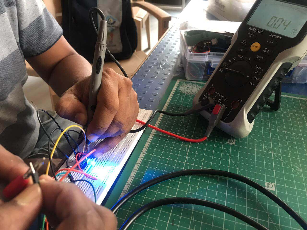
We connected DC motor to the output devices board and ran the motor after
programming the board through arduino IDE. First we measured current in series
and then we measured current in series and voltage across parallel connection
as shown below.
Power consumption of a DC motor: The measured voltage (V) for the DC motor was 10.25 Volts
and the value of current required (I) was varying. However, the one,
which was most consistent was 22.4 mA. So the power consumption of a DC toy motor= P= V x I
= 10.25 x 0.0224 A = 0.2296 Watts.
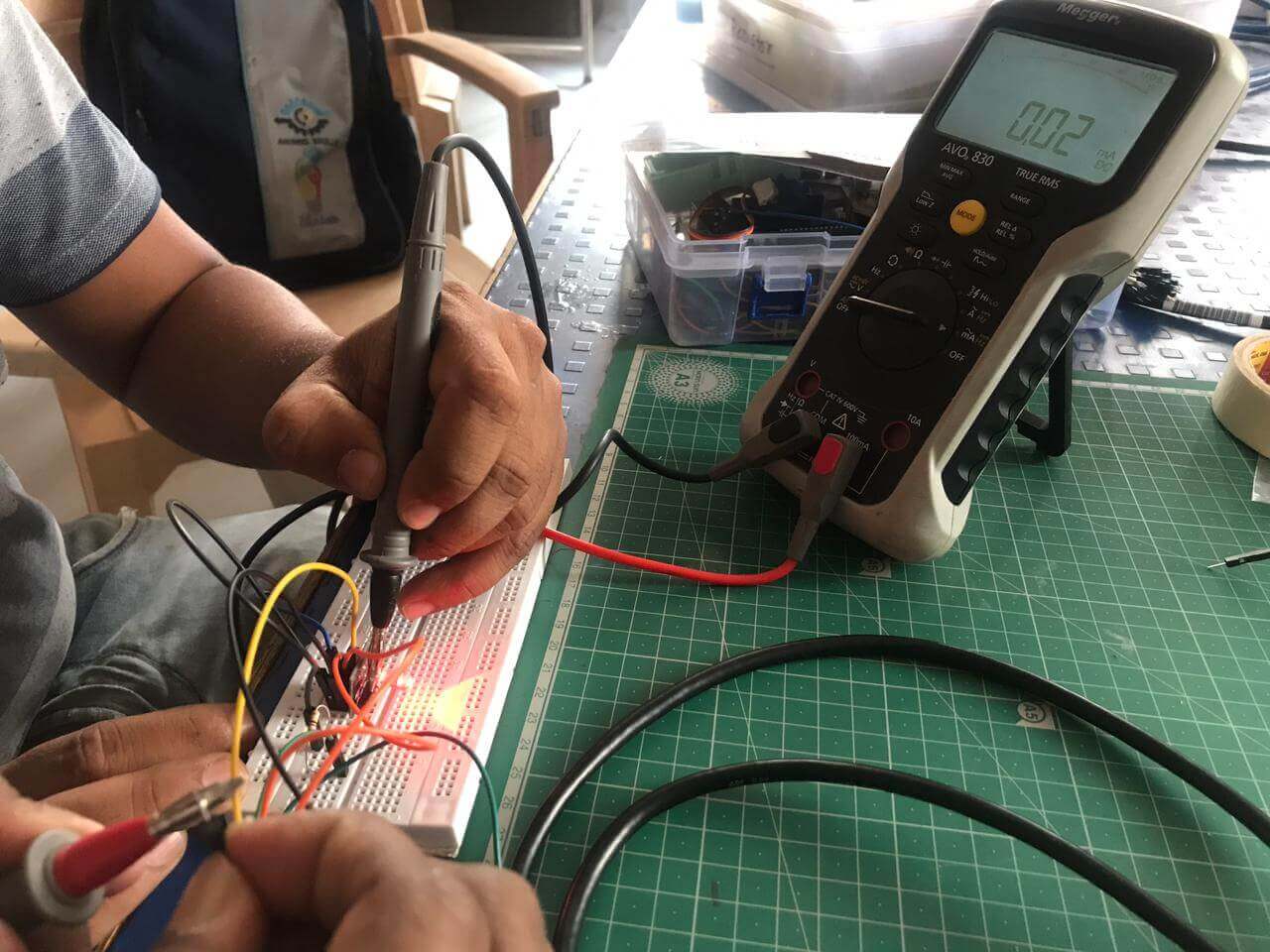
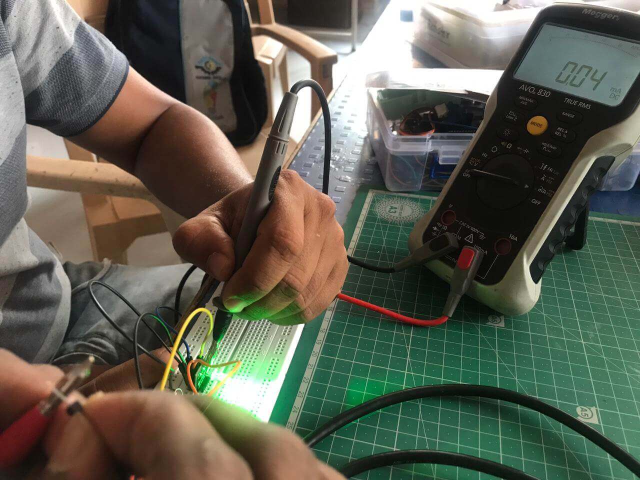
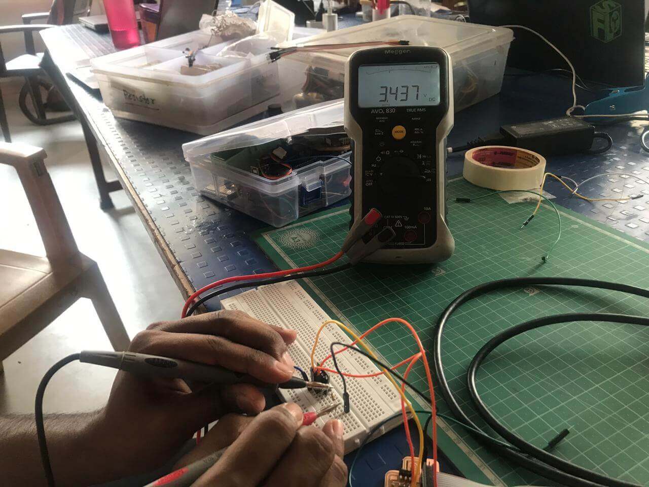
In second case, we connected RGB LED module to the output devices board and blinked each LED
(Red, Green and Blue) separately after
programming the board through arduino IDE. Also measured the current by attaching the
resistor of 80K in series with the help of
Megger make multimeter as shown below.
Power consumption of RGB LED: The operating voltage (V) for RGB LED was 5 Volts and the
value of current (I) was different for Red, Green and Blue LED. For Red LED, it was 0.02 mA,
for Green and Blue LED, it was 0.04 mA. Following are our calculations of power consumption
of RGB LED.
In electronic systems, output devices transfer
energy from processed electrical energy to another
form of energy, usually light, sound, or movement
(kinetic). Digital or analog output devices are
available.
Actuators are electronic devices that perform an "Output" function.
To get started
I am making my final project output board this week.
Use attiny1614
Then when it didn't happen on Attiny 44, I used attiny1614 IC.
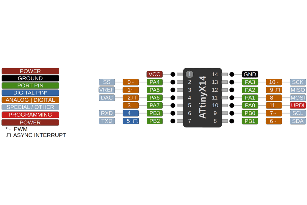
What is the attiny1614.
The ATtiny1614 is a 14-pin microcontroller with an 8-bit AVR® processor with
a hardware multiplier that runs at up to 20 MHz and has 16 KB Flash, 2 KB SRAM,
and 128B of EEPROM.
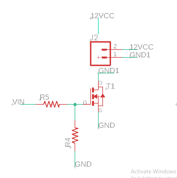
A N-Channel MOSFET is a type of MOSFET in which the
channel of the MOSFET is composed of a majority of
electrons as current carriers. When the MOSFET is
activated and is on, the majority of the current
flowing are electrons moving through the channel.
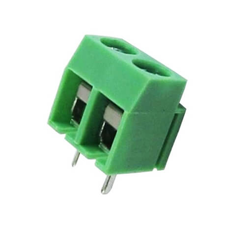
This 2 Pin Wire to Board connector are used widely for connecting Wires to
Boards, It can be for Power Supply or connecting any other perpheral like
Motor to the Board. The distance between two mounting pins is in multiple
of standard 5mm so that this connector can be mounted easily on general
purpose PCBs.
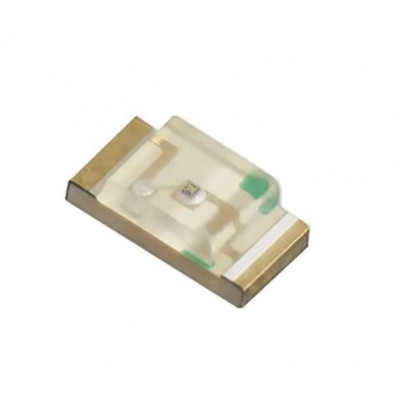
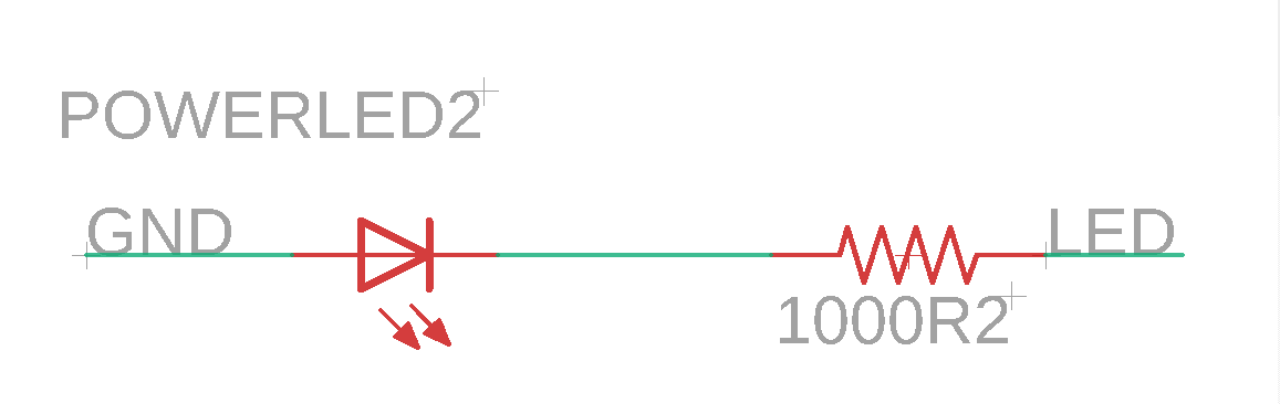
A light-emitting diode (LED) is a semiconductor light source that emits light when
current flows through it. Electrons in the semiconductor recombine with electron holes,
releasing energy in the form of photons. The color of the light (corresponding to the energy
of the photons)
is determined by the energy required for electrons to cross the band gap of the
semiconductor.
White light is obtained by using multiple semiconductors or a layer of light-emitting
phosphor on the semiconductor device.
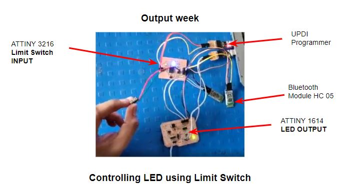
When the button is pressed from Attiny3216, the LED from Attiny1614 will be turned ON.
So this week I'm going to turn the LED on and off.
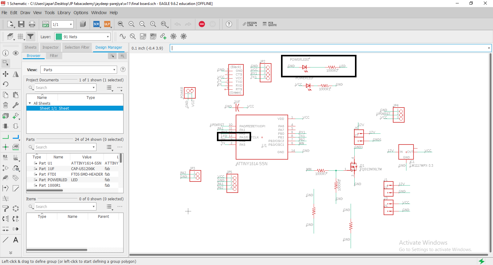
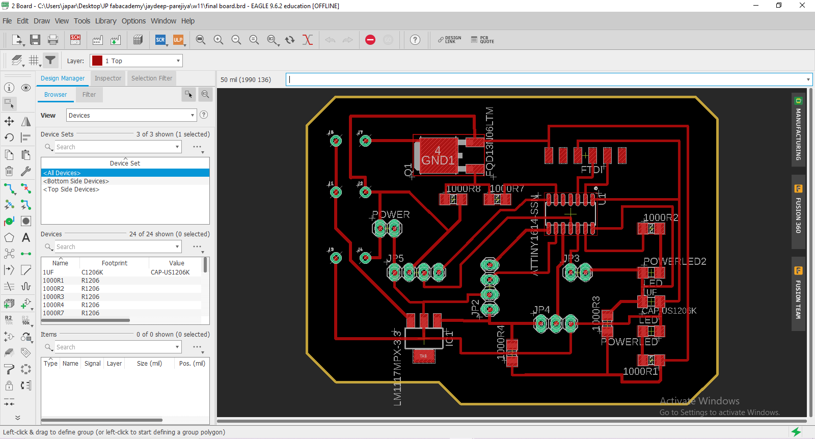
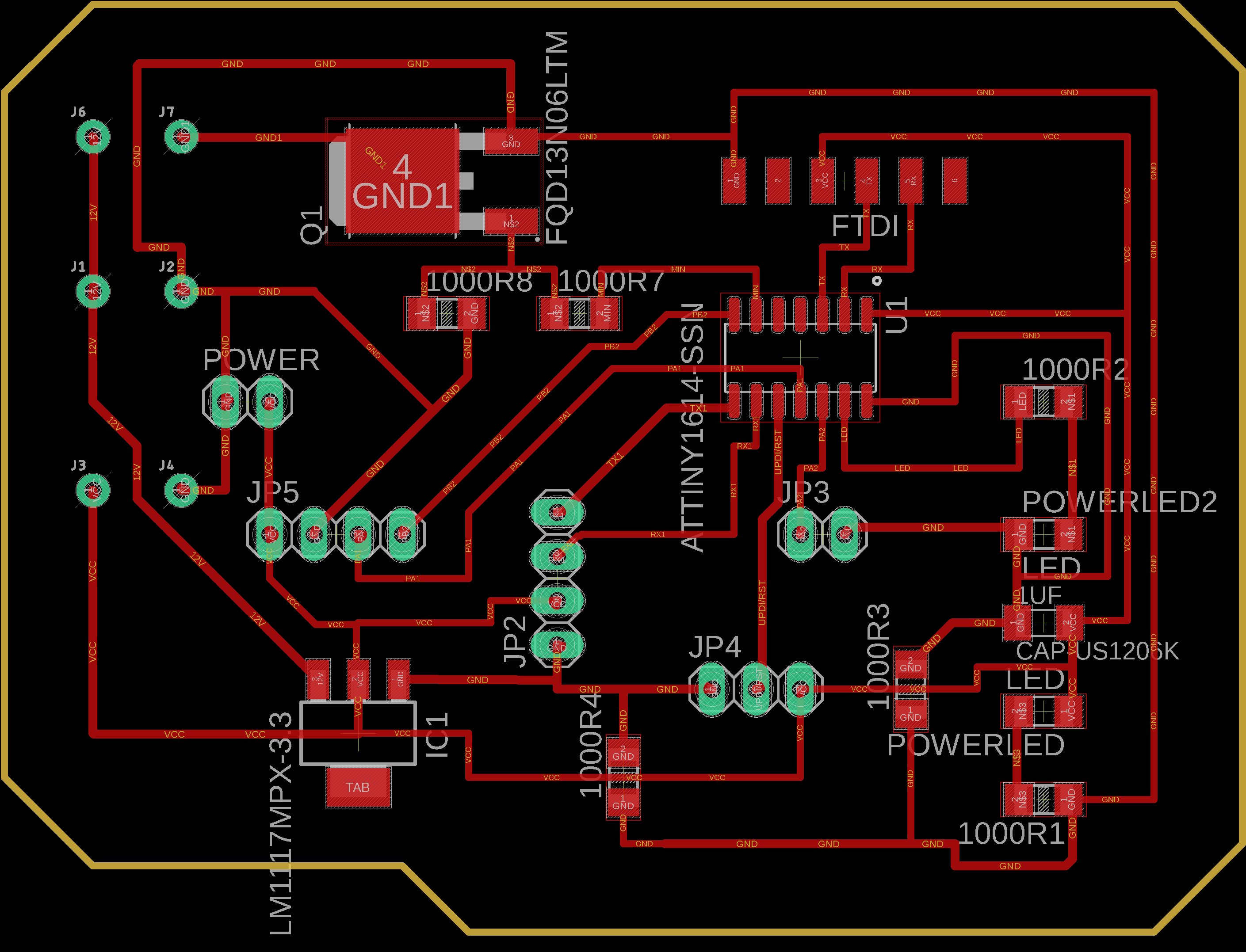
Eagle
Add Attiny1614 IC.
My LED pin is number PA3.
SMD LED Schematic
NPN Mosfet diagram my Schematic.
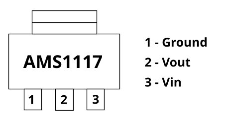
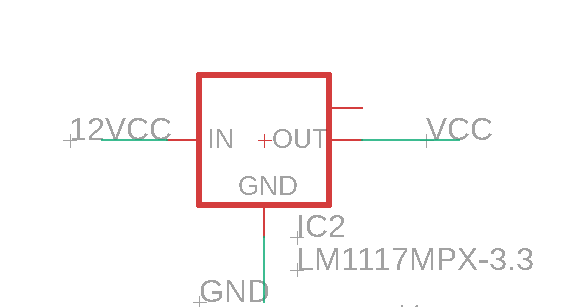
AMS1117 5v regulator diagram.
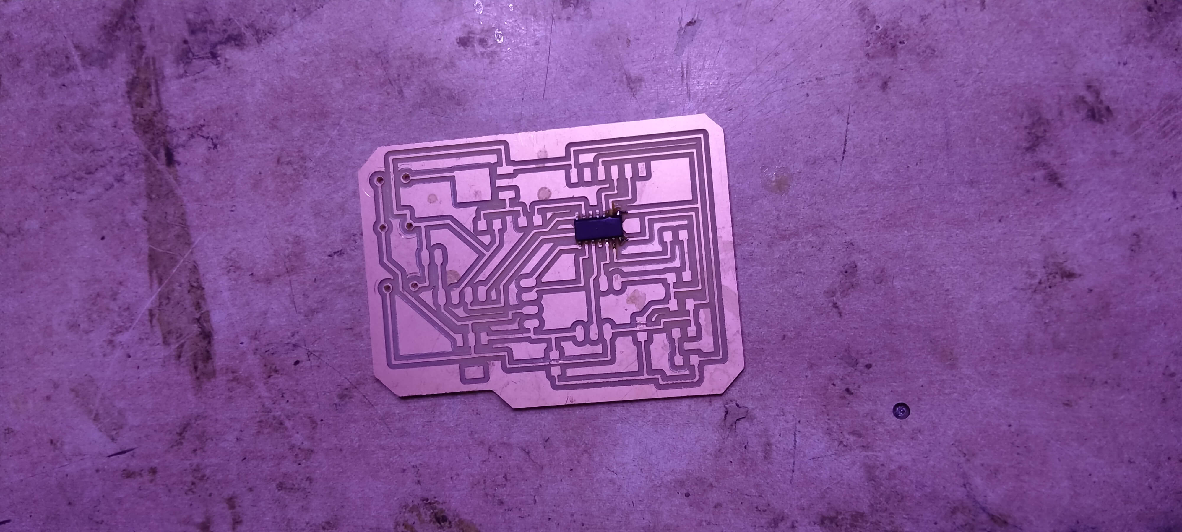
Milling Machining
Video
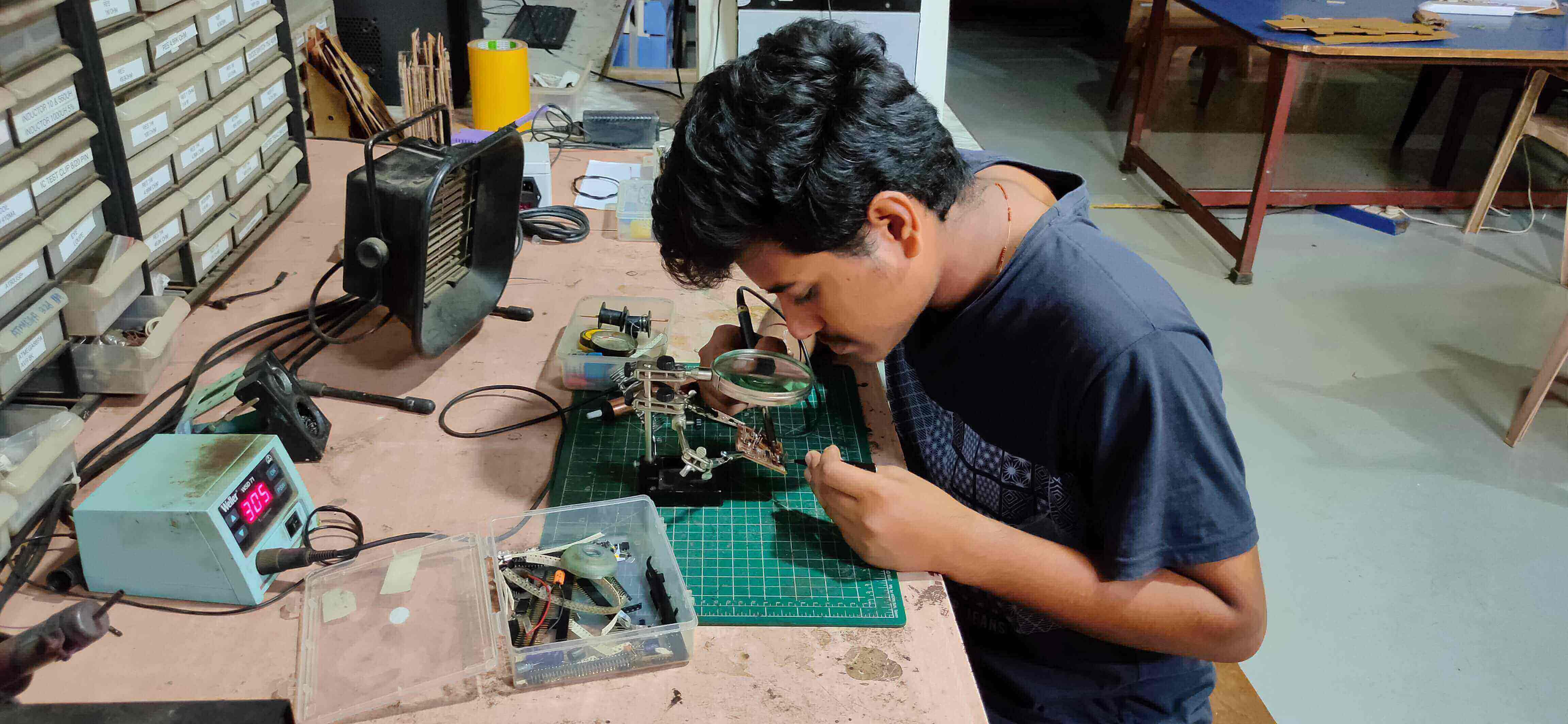
Soldering
Solder Attiny1614.
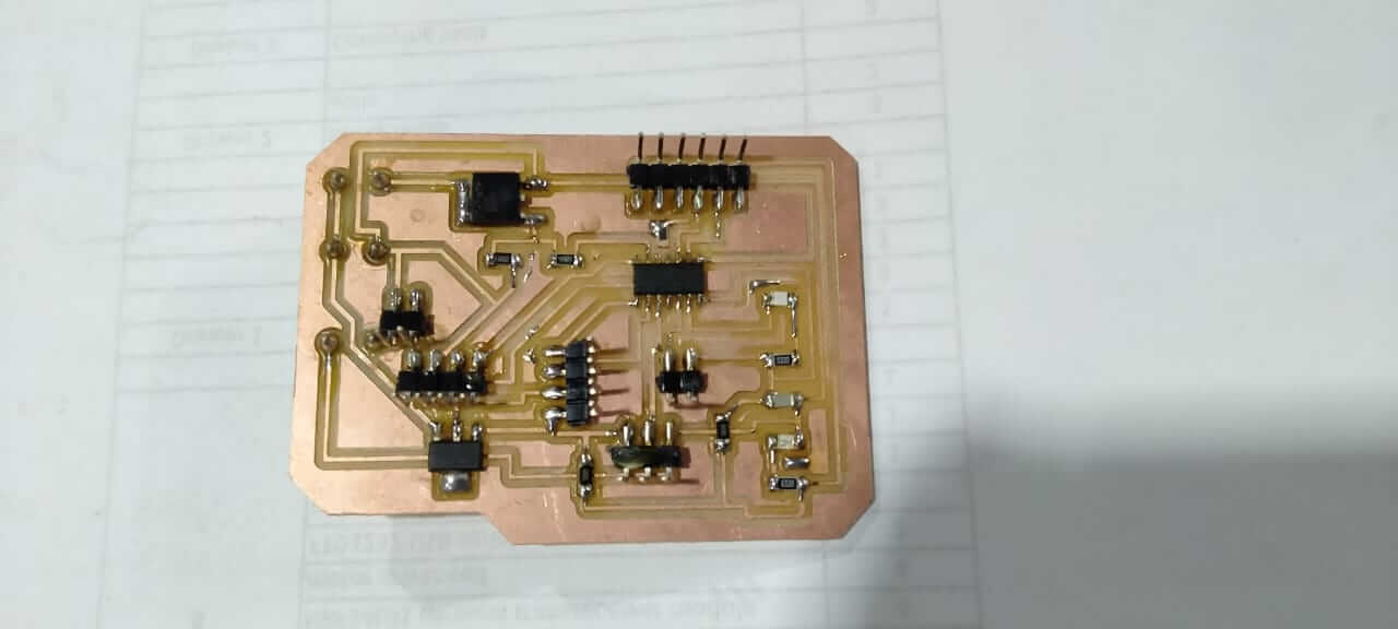
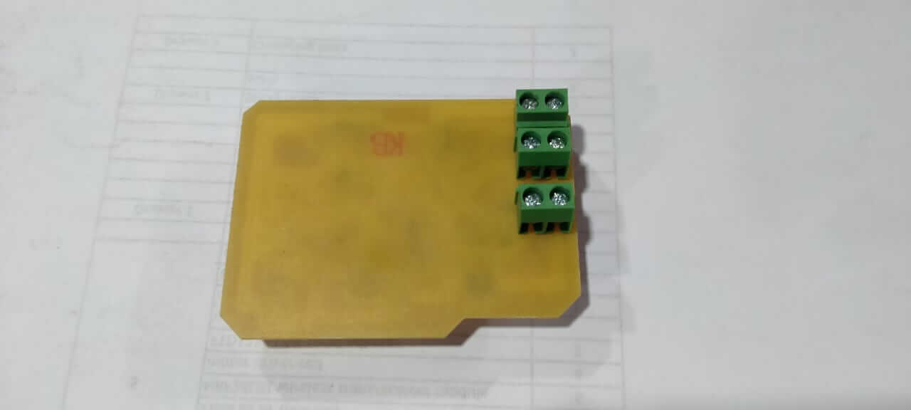
Solder Board Photo
Programming
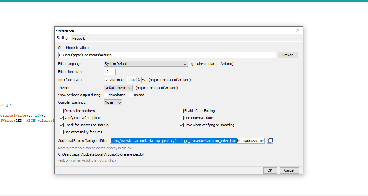
Enter the Preferences Key.
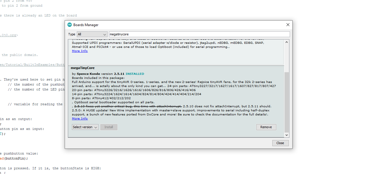
download "megatinycore" Board.
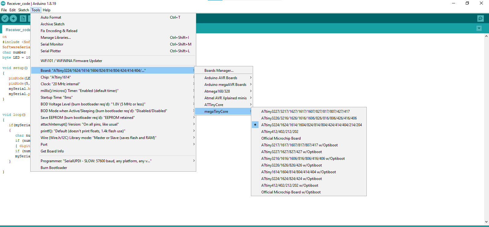
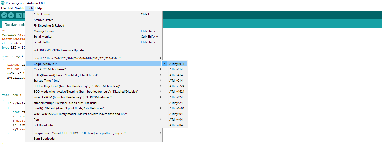
Then Select ATtiny1614 board.
Select Chip ATtiny1614.
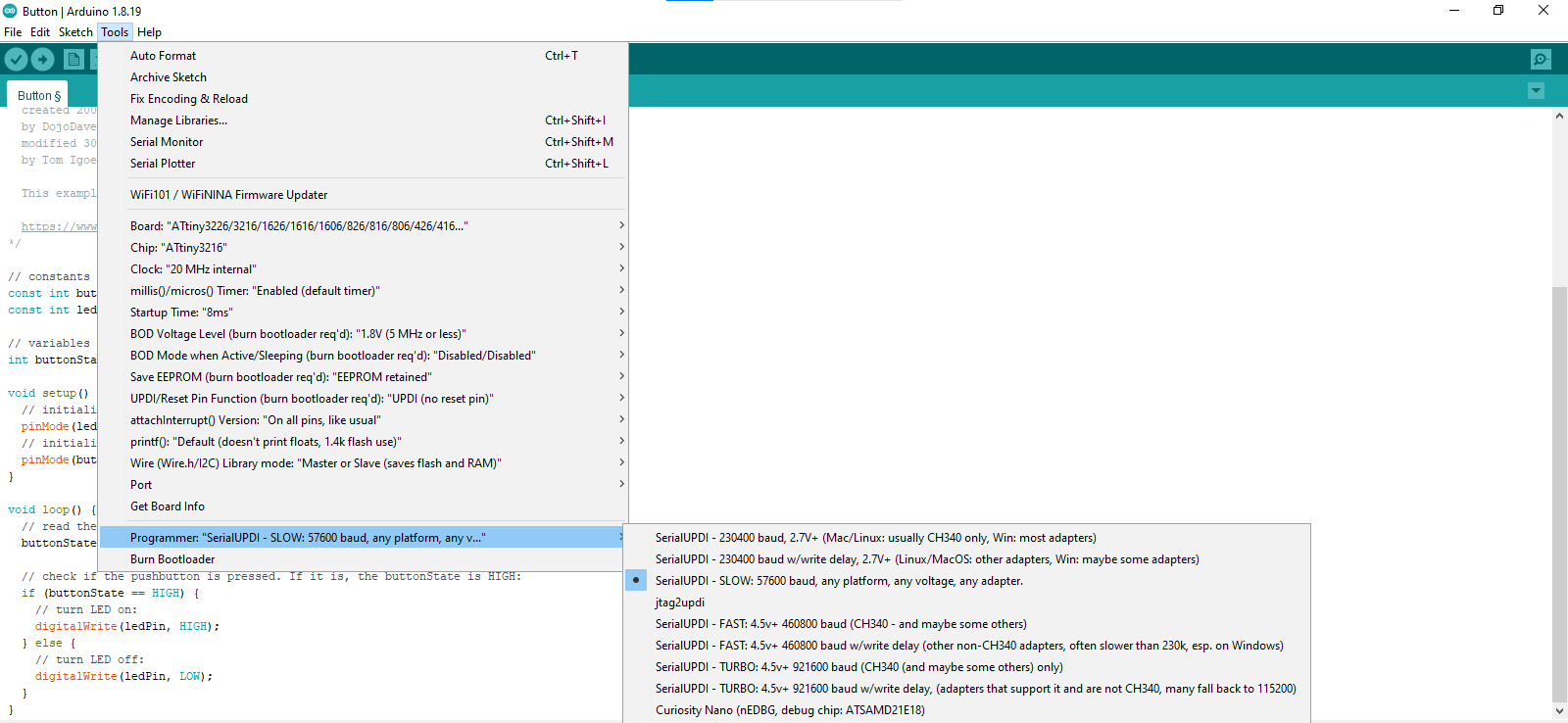
Then Select Programmer.
Code Upload My board.
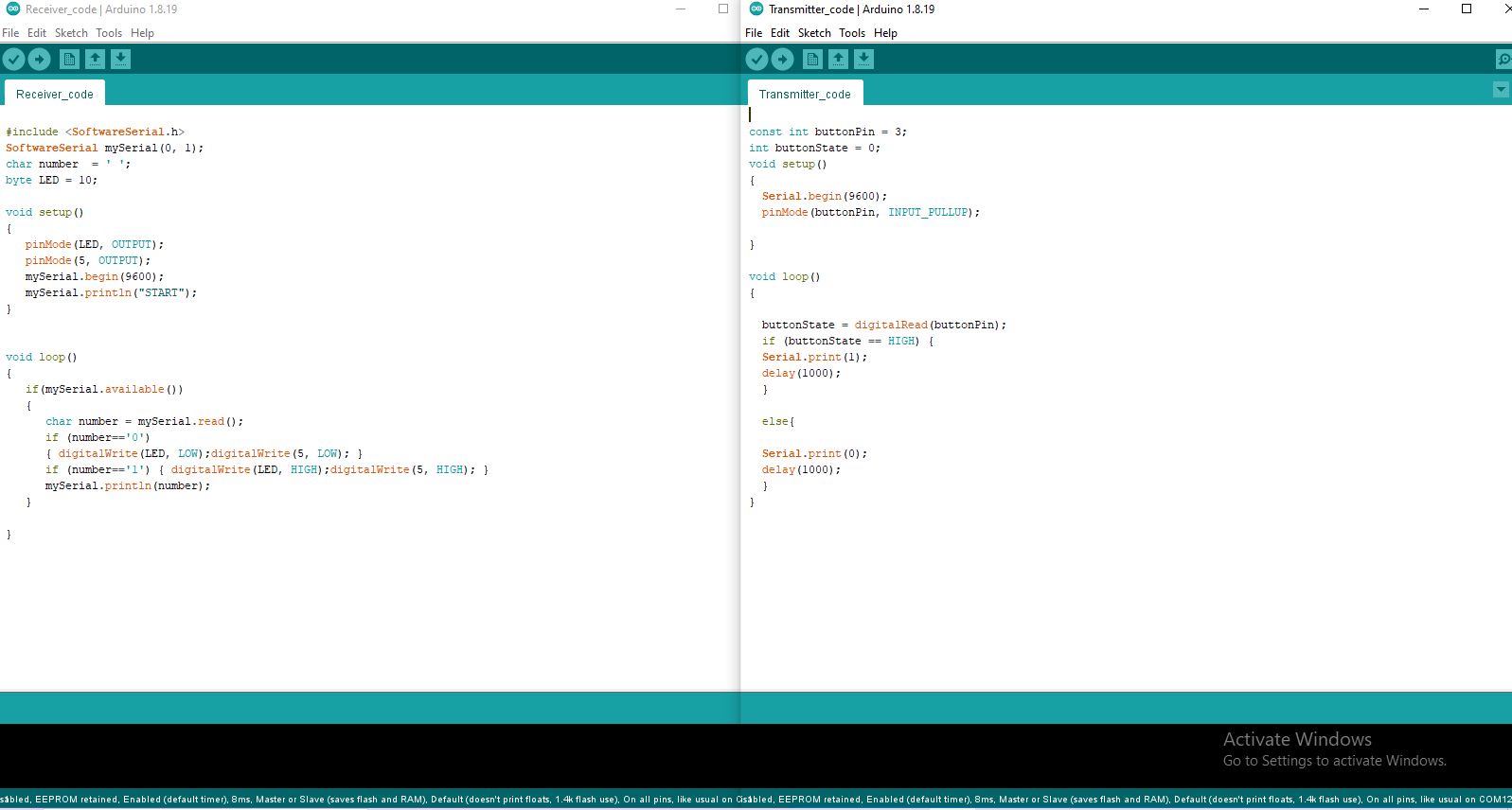
RX Code Upload Attiny1614 IC.
TX Code Upload Attiny3216 IC.
Attiny1614 Board Code.
Within the code, RX and TX Pin 0,1 pins are defined for Bluetooth.
And the pin number 10 is the LED pin.
And the pin number 5 is the relay pin.
Attiny3216 Board Code.
Final Video
transfer signal Attiny3216 To Attiny1614.
I installed one Bluetooth Attiny1614 inside and another Bluetooth Attiny3216 board.
And then I created a Bluetooth master and another Bluetooth slave.
Bluetooth HC05- How to pair two modules Tutorial
Link
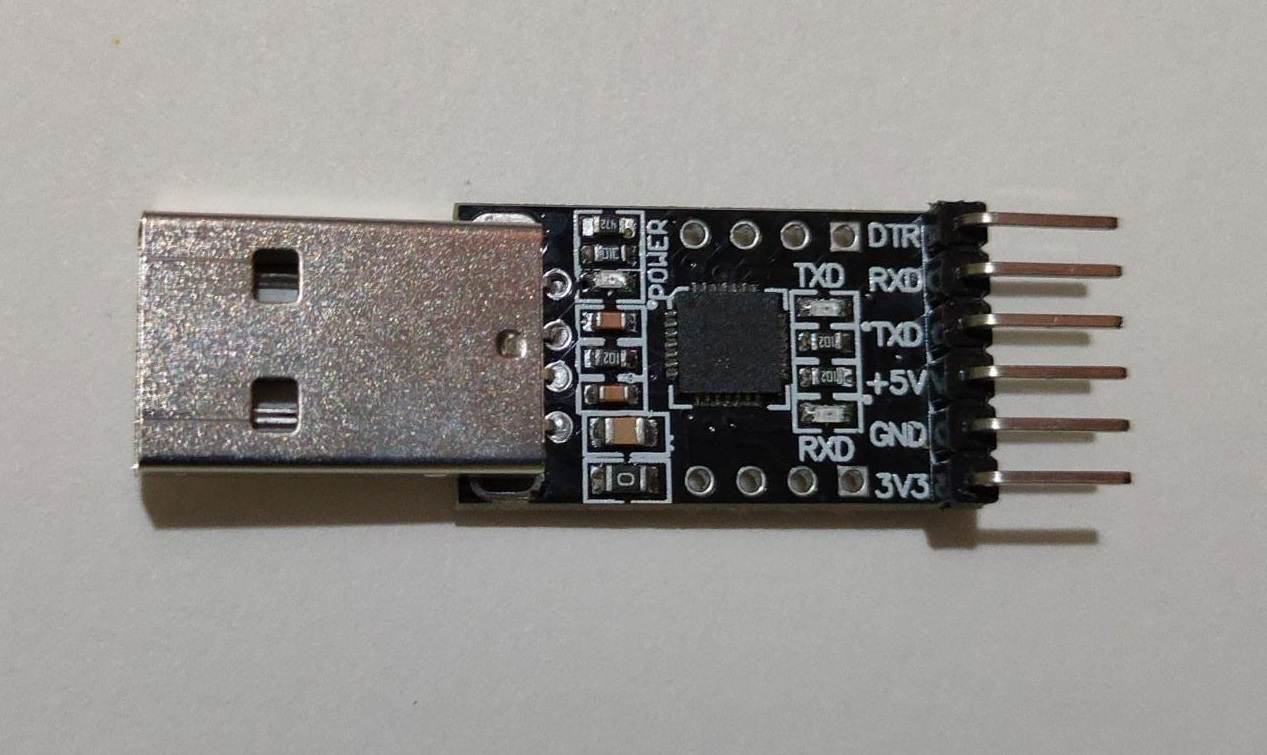
UPDI Programmer Photo
SRM-20
I was thinking to add mark out using the circle so can get the perfect postion and then manually drill it.
Explain Board Photo
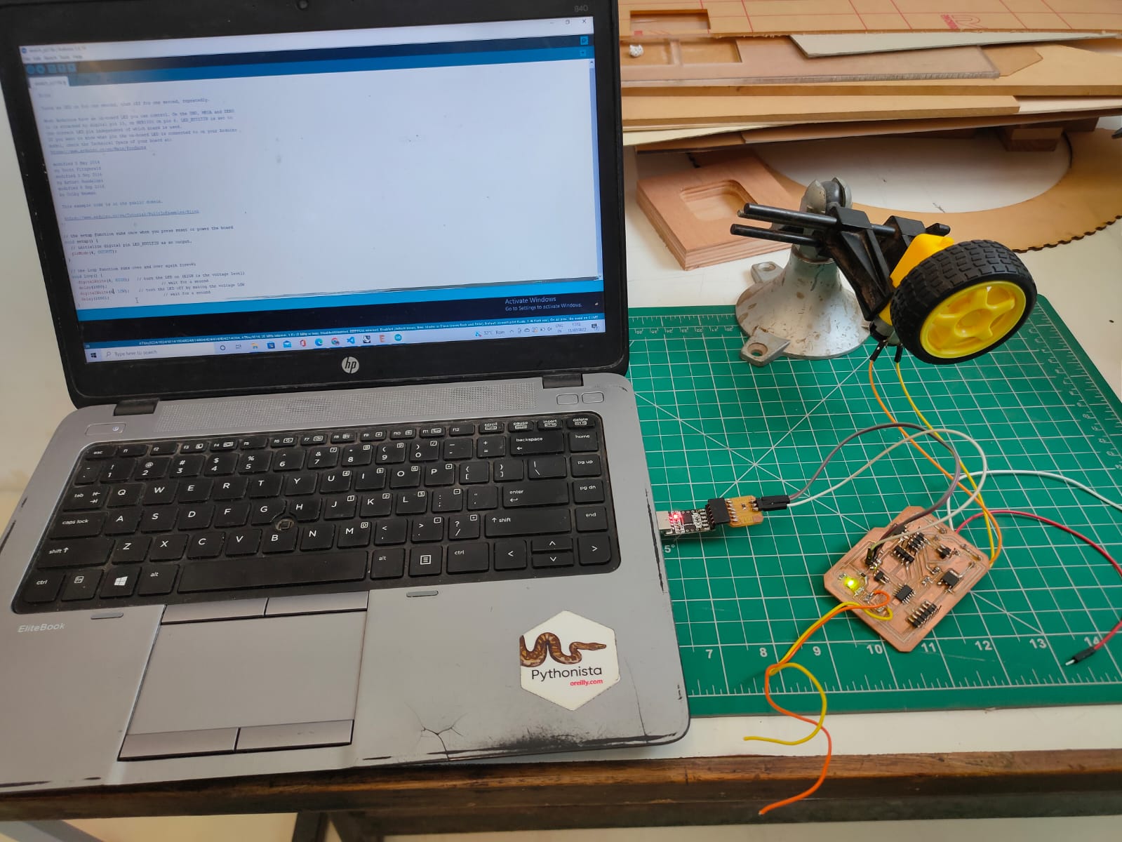
Mosfet With Bo Moter
\
In this video I am controlling the bo motor from my mosfet. The pin number of the mosfet is PB3. And my Bo motor is connected to the bottom side screw connector.