13. Input devices
An input device responds to changes in the environment and produces a suitable electrical signal for processing in an electronic circuit. In all input devices, other forms of energy are transformed into electrical energy.
Example of input devices: - Microphone - Thermistor - Switches
Learning outcomes:
• Demonstrate workflows used in sensing something with input device(s) and MCU board
Like the previous weeks , student are expected to complete two (2) categories of weekly assignment.
-
Group assignment: Probe an input device(s)’s analog and digital signals o Document your work to the group work page and reflect on your individual page what you learned
-
Individual assignment: Measure something: add a sensor to a microcontroller board that you have designed and read it.
Group Assignment
For our Group assignment we had to Measure the power consumption of an output device and document our findings.
The Group Assignment page is as follows Link
Group Members:
-
Nervene Bhagwandass
-
Christopher Proute
-
Ravi Baldeo
-
Marvin Holloway
-
Terrence Carew
-
James Khan
Individual Assignment
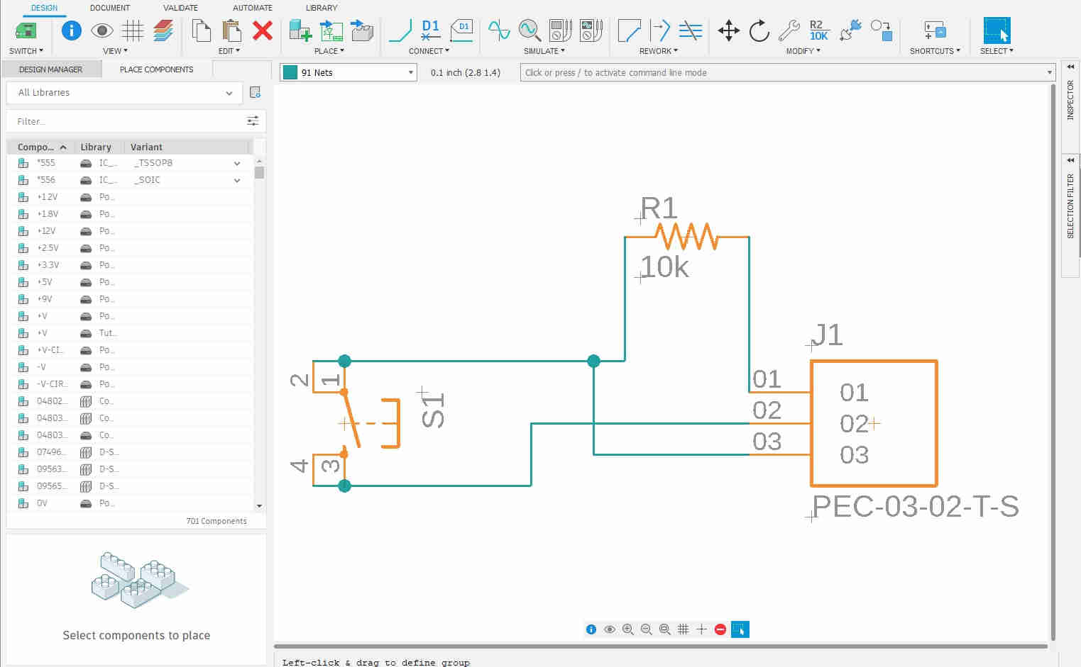
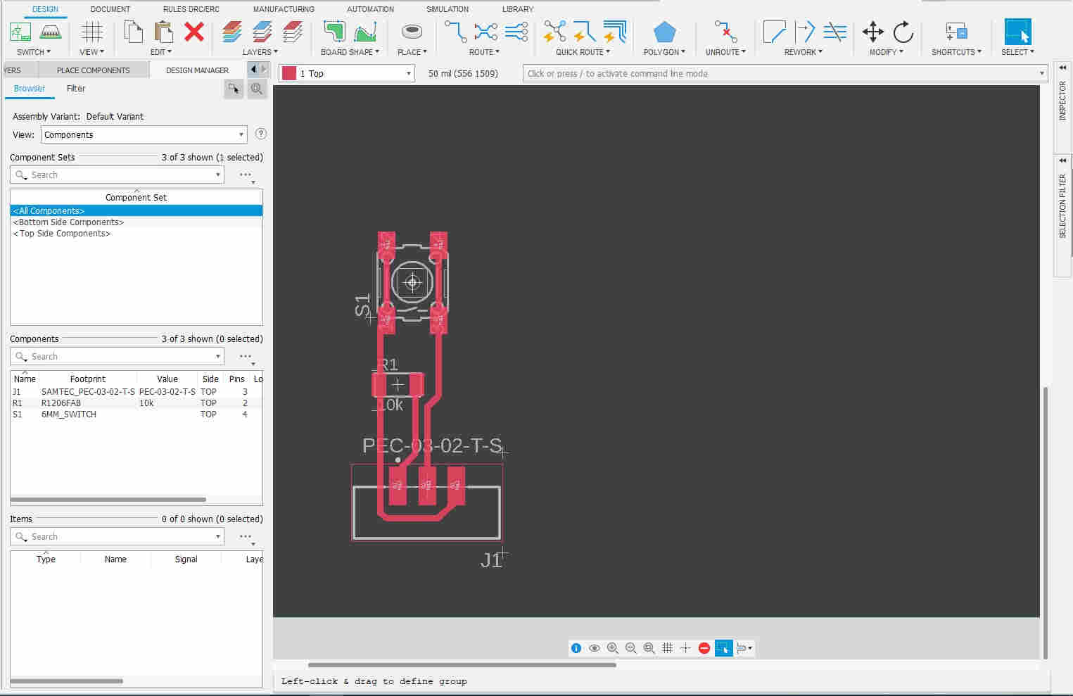
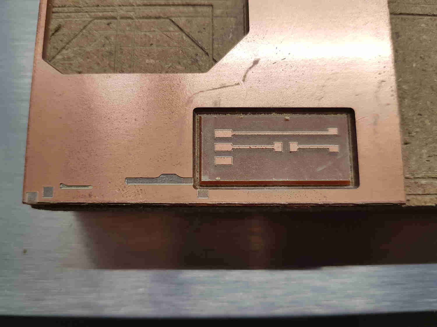
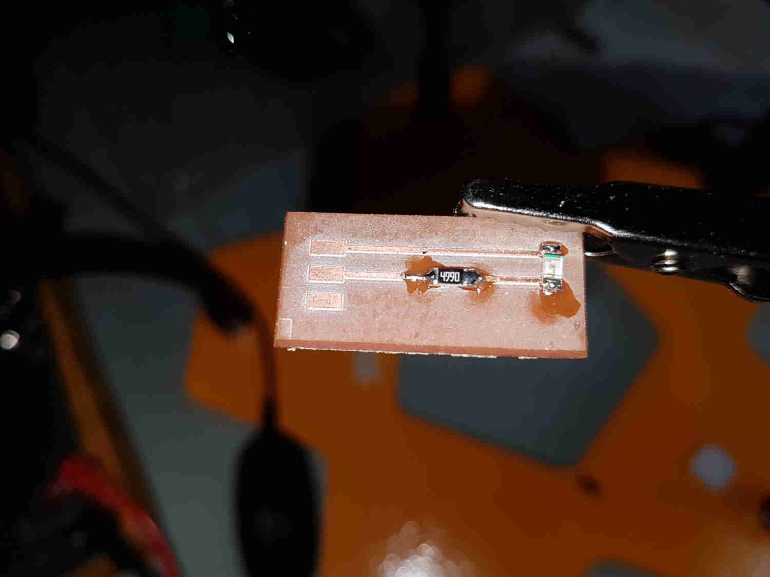
For my individual assignment for input devices, I utilized my Output week circuit board and designed several input modules
-
Switch (input)
-
Hall effect (input)
-
Led (output)
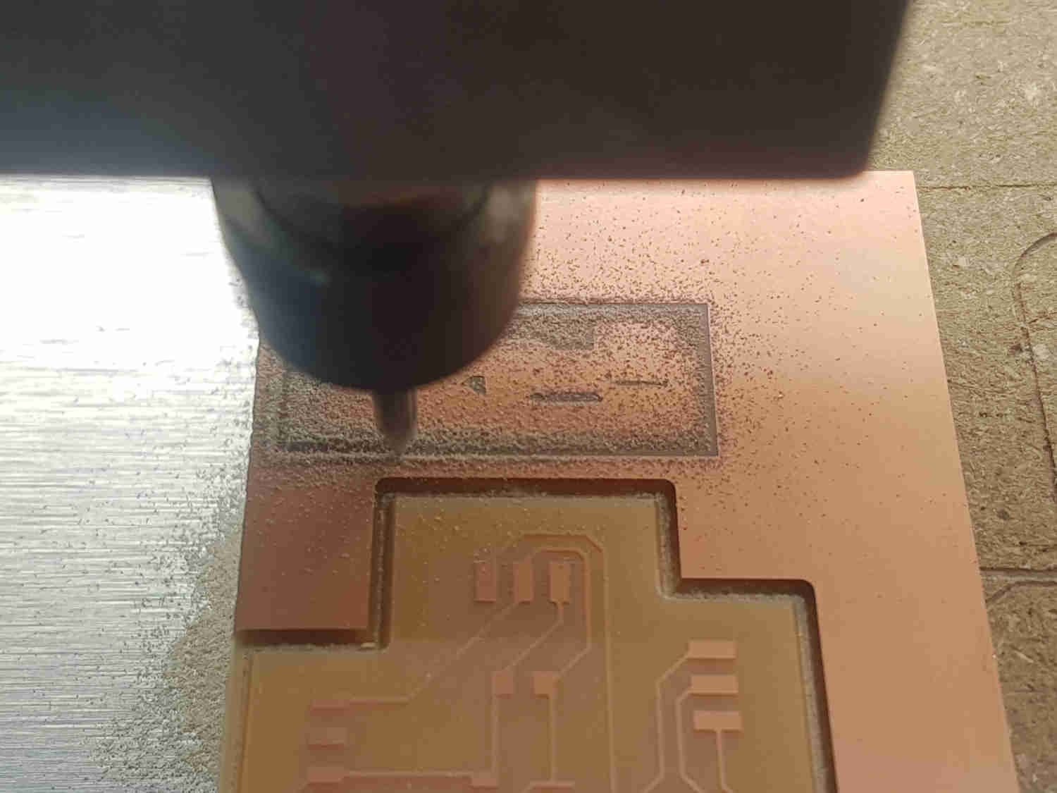
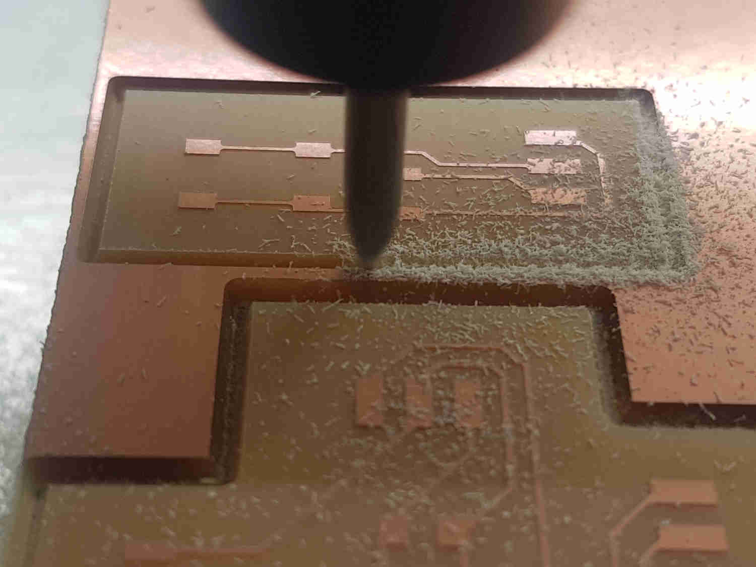
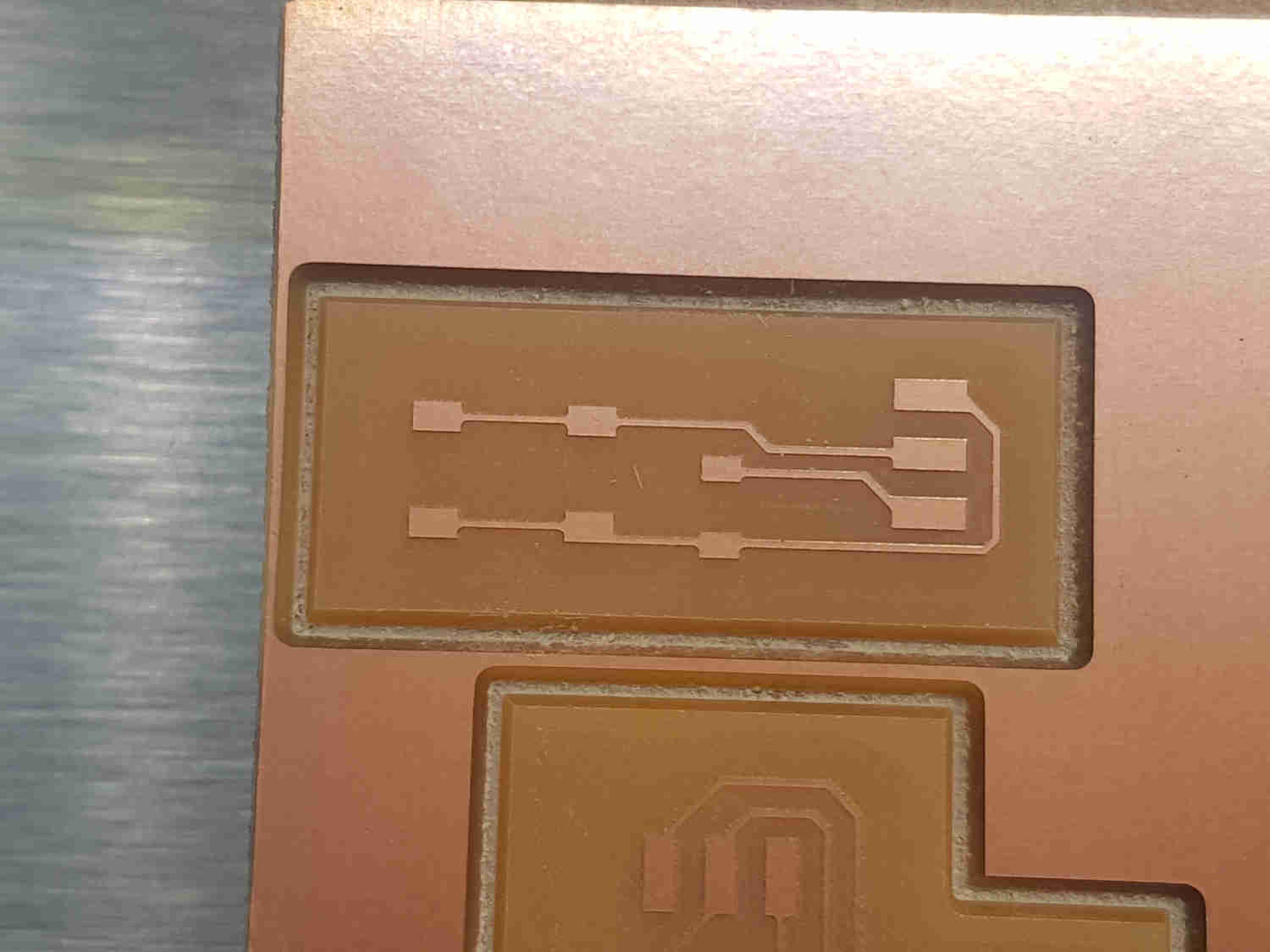
Output week Circuit Board


Switch
I did not use the switch
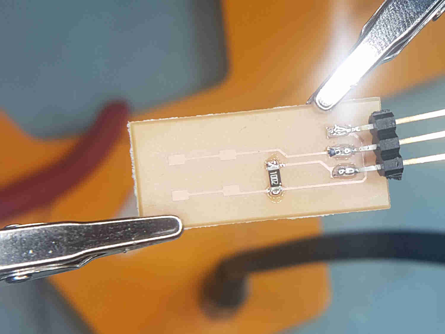

Hall Effect
A Hall effect sensor is a type of sensor which detects the presence and magnitude of a magnetic field using the Hall effect , either to switch a circuit on and off.


LED

Programming
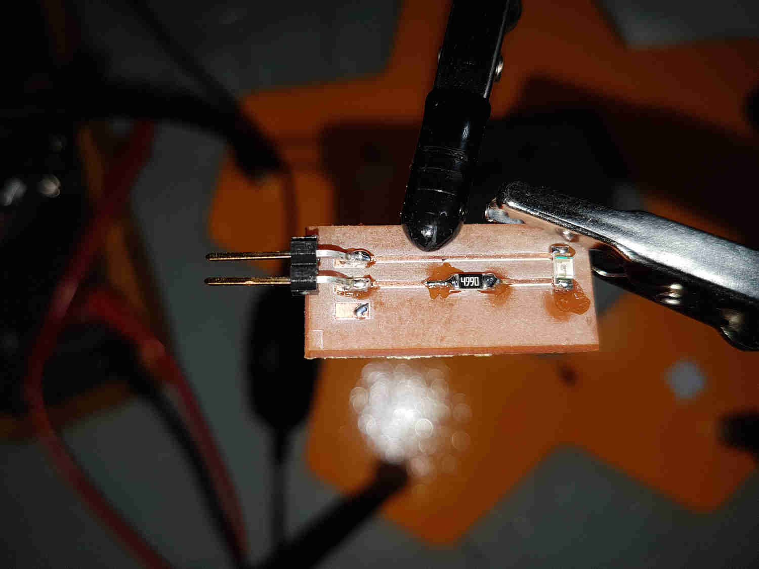
I connected my FTDI cable > UPDI> electronic design board.
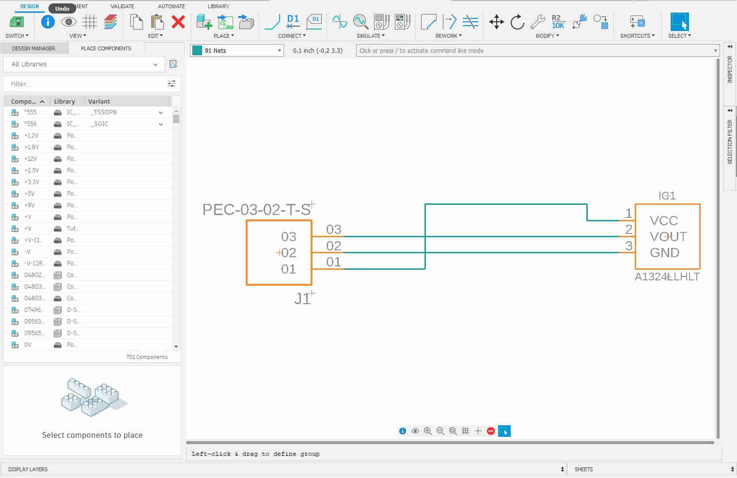
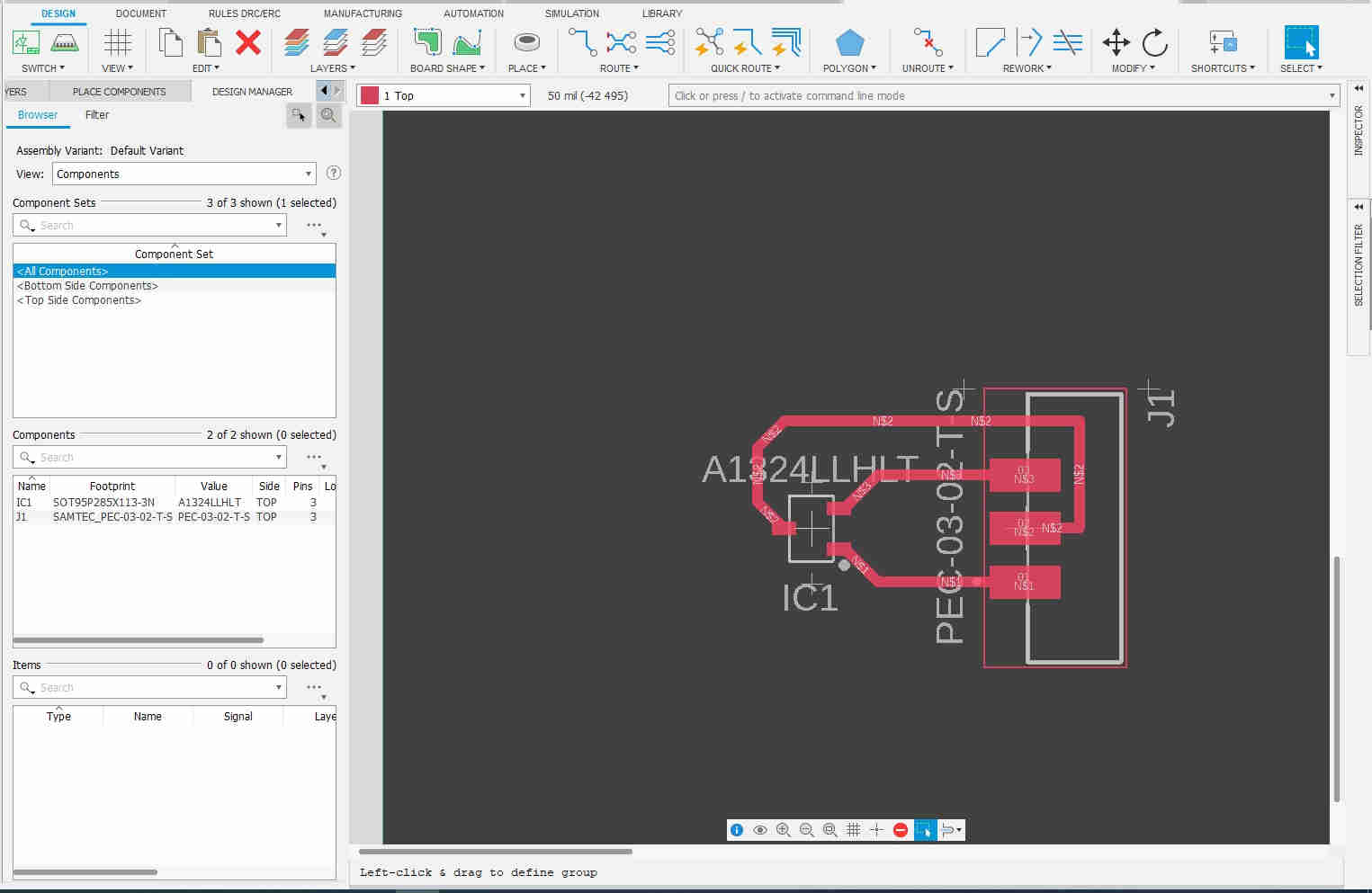
I then modified the code from my Embedded programming week I had to define a library containing ATtiny412 details, which is why the first line is #include and then the pin name to be configured. According to my schematic, the Hall effect is connected to pin PA1 and the LED is connected to pin PA2. Next I need to configure the Hall effect sensor as input and LED as output. This explains the statement pinMode again. Note that when the hall effect sensor is activated with a magnet it opens or closes the circuit . I then clicked on the upload program to load it into the ATtiny microcontroller.

#include <avr/io.h>
#define HALL EFFECT PIN_PA1
#define LED   PIN_PA2
void setup() {

  // initialize digital pin LED_BUILTIN as an output.
pinMode(HALL EFFECT, INPUT);
  pinMode(LED, OUTPUT);
}

// the loop function runs over and over again forever
void loop() {
  if(!(digitalRead(HALL EFFECT))) //if BUTTON is pressed turn on LED
 digitalWrite(LED, HIGH);
 else  //else turn OFF
 digitalWrite(LED, LOW);

}