12. Output devices
Group assignment:
Measurement of the consumption power of a stepper motor
For this experience, a stepper motor model 28BYJ was used, whose characteristics are:
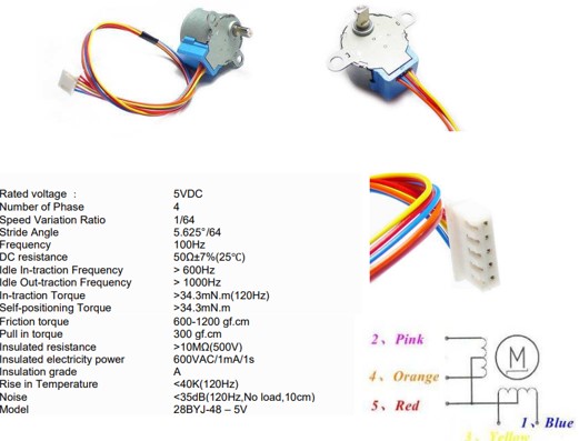
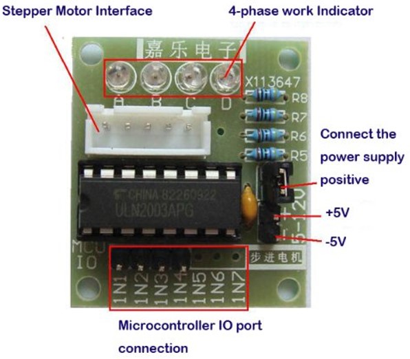
For rotation control we can use a board with integrated ULN2003. Normally the 28BYJ-48 is used with this board, and both devices have connectors for easy connection.
Circuit implementation
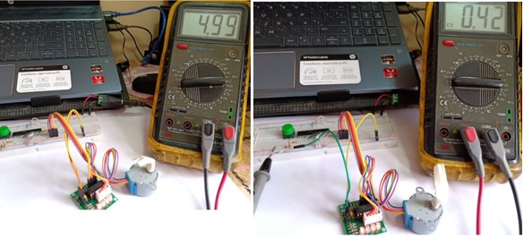
To find the power consumed by the motor, the equation P(w) = VxI is used, since we are working in direct current, The image on the left shows the measurement of the voltage supplied by the power supply to the control circuit and the stepper motor, The image on the right side shows the measurement of the current circulating on the card with the ULN 2003, which is responsible for amplifying the current that is delivered to the stepper motor. According to the values obtained we calculate the power in the stepper motor as follows:
P = VxI = 4.99v X 0.42 A = 2.1 W.
Individual reflection
What has been learned in the development of this experience is that to run a stepper motor it is necessary to have an interface that amplifies the current of the signals emitted by the microcontroller, you can not directly connect the motor to the microcontroller because the current it supplies in its ports is not enough to run the motor, and we would cause irreversible damage to the microcontroller.
Individual assignment:
For this experience we will use the design with the ATMEGA 328p microcontroller, as it is the one, we find most in the Peruvian market, for experience it consists of controlling the change of rotation of a DC motor and displaying it on a display. As a driver for engine control, we will use the L298N whose characteristics are as follows.
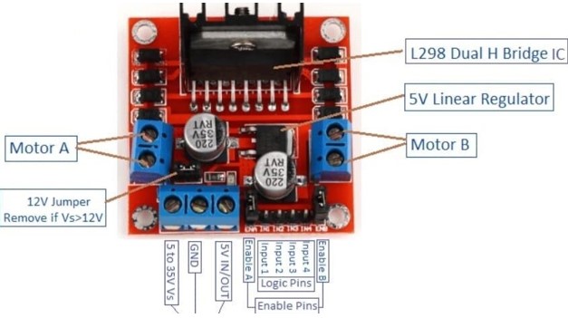
L298N Motor Controller Specifications
The module will allow you to control the speed and direction of two dc current motors. It can control motors operating between 5 and 35V and up to 2A. The module has a built-in regulator that helps to give the output of 5V. The module can be powered from 5 to 35V from a microcontroller or from an external power supply. It is recommended to always use the external power supply. You can also control a stepper motor. It is economical and perfect for robotics projects.
Motor used for the experience
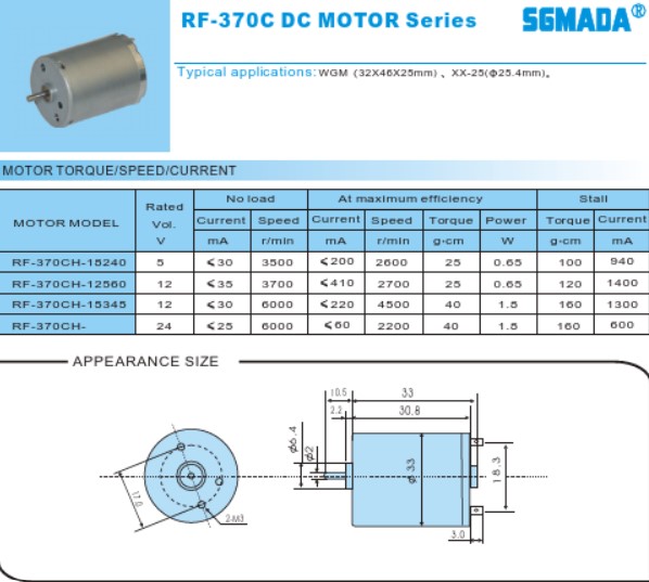
We will use the RF 370C model motor whose characteristics are the following:
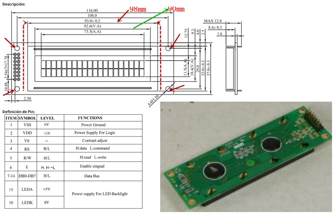
Used LCD 16x2 screen E169497
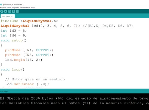
Development of the circuit program
To perform the rotation control program, the Arduino IDE was used for its versatility in programming.
Dc motor rotation control circuit simulation
The simulation was done using the Proteus 8.6 software, I did it in this software because I have the license and I can correct errors before the implementation of the circuit.
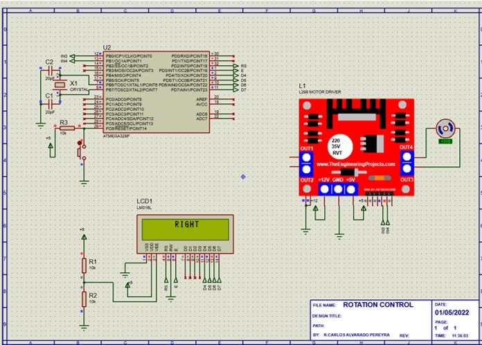
The board developed is based on the ATMEGA 328P microcontroller, in the video you can see the operation of the circuit.