14. Networking and communications
Task: Embedded Networking and Communications
- Group assignment:(Page Link is Here)
- Send a message between two projects
- Individual assignment:
- design, build, and connect wired or wireless node(s) with network or bus addresses
In this week I explored and learned about different communication protocols.
In the begining of this week, I tried to learn about communication protocol and networks from internet.
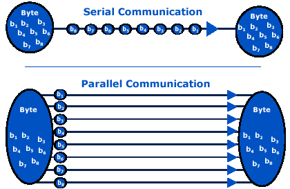
Serial communication: Process of sending data one bit at a time, sequentially over a communication channel.
Parallel communication: Process of sending multiple bits as a whole on a link with several parallel channels.
https://www.differencebetween.com/difference-between-serial-and-parallel-communication/
wikipedia.
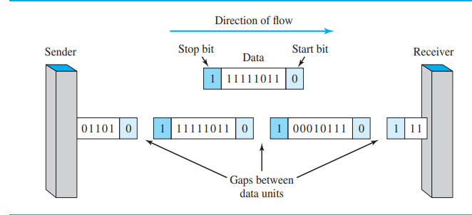
Types of Serial Communications
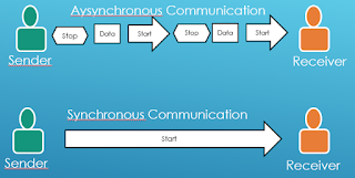
- Synchronous − Devices that are synchronized use the same clock and their timing is in synchronization with each other.
- Asynchronous − Devices that are asynchronous have their own clocks and are triggered by the output of the previous state
https://electronics.stackexchange.com/
I decided to work with i2c communication in this week.
i2c protocol
This is a type of synchronous serial communication protocol. It means that data bits are transferred one by one at regular intervals of time set by a reference clock line.
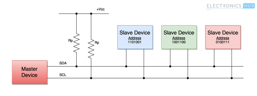
Features
- only 2 bus lines are required(SDA and SCL).
- SDA and SCL are open collector signals so they should be connected to VCC using two separate pull up resistors.
- Each slave will have unique address. It differentiate them from other slaves on the bus.
I read a tutorial and it helped me to understand about i2c protocol very clearly (Link here)
Testing i2c protocol.
After understanding about i2c protocol, Arun Boby and I tested i2c using samd21e17a boards made in our output week.
- We studied a simple 2 Arduino board project from the internet. And then we modified that code for our boards.
Connection
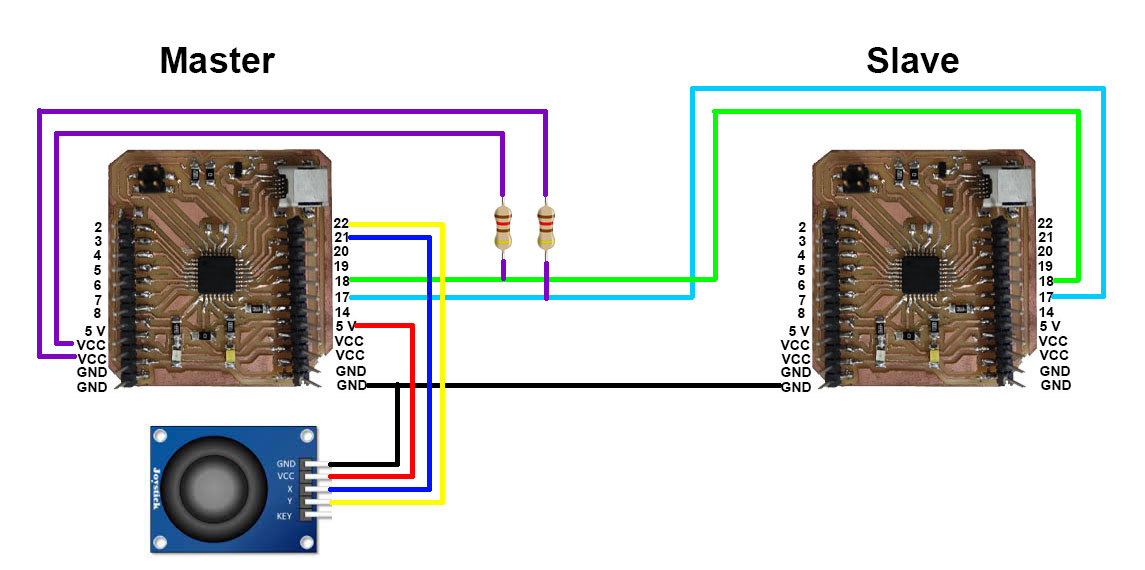
- We spend a lot of time for operating i2c protocol. It didn’t work because of some following reasons.
- Samd21e has more than one SDA-SCL pin group. And only one of them is the default. Without this knowledge, we spend a little time with board testing and code editing.
- We tried different SDA-SCL pins and wrote a code for printing digital reading of those pins in the serial monitor in the system where the slave board connected. Code is given below.
#include<Wire.h>
//#define DEBUGGING
int x = 0;

void setup() {
  pinMode (8, OUTPUT);

#ifndef DEBUGGING
  Wire.begin(9);
  Wire.onReceive(receiveEvent);
#endif

  SerialUSB.begin(9600);

#ifdef DEBUGGING
  pinMode(22, INPUT);
  pinMode(23, INPUT);
#endif

}
void receiveEvent(int bytes) {
  int x = Wire.read();
  SerialUSB.print(x);
}

void loop() {
#ifndef DEBUGGING
  SerialUSB.println(x);
  delay(1000);
#endif
#ifdef DEBUGGING
  SerialUSB.print(digitalRead(22));
  SerialUSB.print(" ");
  SerialUSB.println(digitalRead(23));
#endif
}
- We didn’t connect pullup resistor for SDA and SCL pins.
However at last we could make communicate the boards together and we wrote a code for controlling a led with one axis of joystick.
Code for master board:
//MASTER BOARD
#include<Wire.h>//This library is used for I2C communication
int x;
void setup() {
  Wire.begin(150);
  SerialUSB.begin(9600);
}
void loop() {
  x = analogRead(2);//Reading value from Potentiometer
  x/=4;
  Wire.beginTransmission(150);//9 here is the address of the slave board
  Wire.write(x);//Transfers the value of potentiometer to the slave board
  Wire.endTransmission();
  SerialUSB.println(x);
  delay(1000);
}
Code for slave board:
//Code for the slave board
#include<Wire.h>
int x;
void setup() {
  pinMode (8, OUTPUT);//Connect LED to pin 13
  Wire.begin(150);//9 here is the address(Mentioned even in the master board code)
  Wire.onReceive(receiveEvent);
  SerialUSB.begin(9600);
}
void receiveEvent(int bytes) {
  x = Wire.read();//Receive value from master board
  SerialUSB.println(x);
}
void loop() {
  if (x > 210) {//I took the threshold as 88,you can change it to whatever you want
    digitalWrite(8, HIGH);
  }
  else if(x < 195){
    digitalWrite(8,HIGH);
    delay(100);
    digitalWrite(8,LOW);
    delay(100);
  }
  else{
    digitalWrite(8, LOW);
  }
}
Making a new board
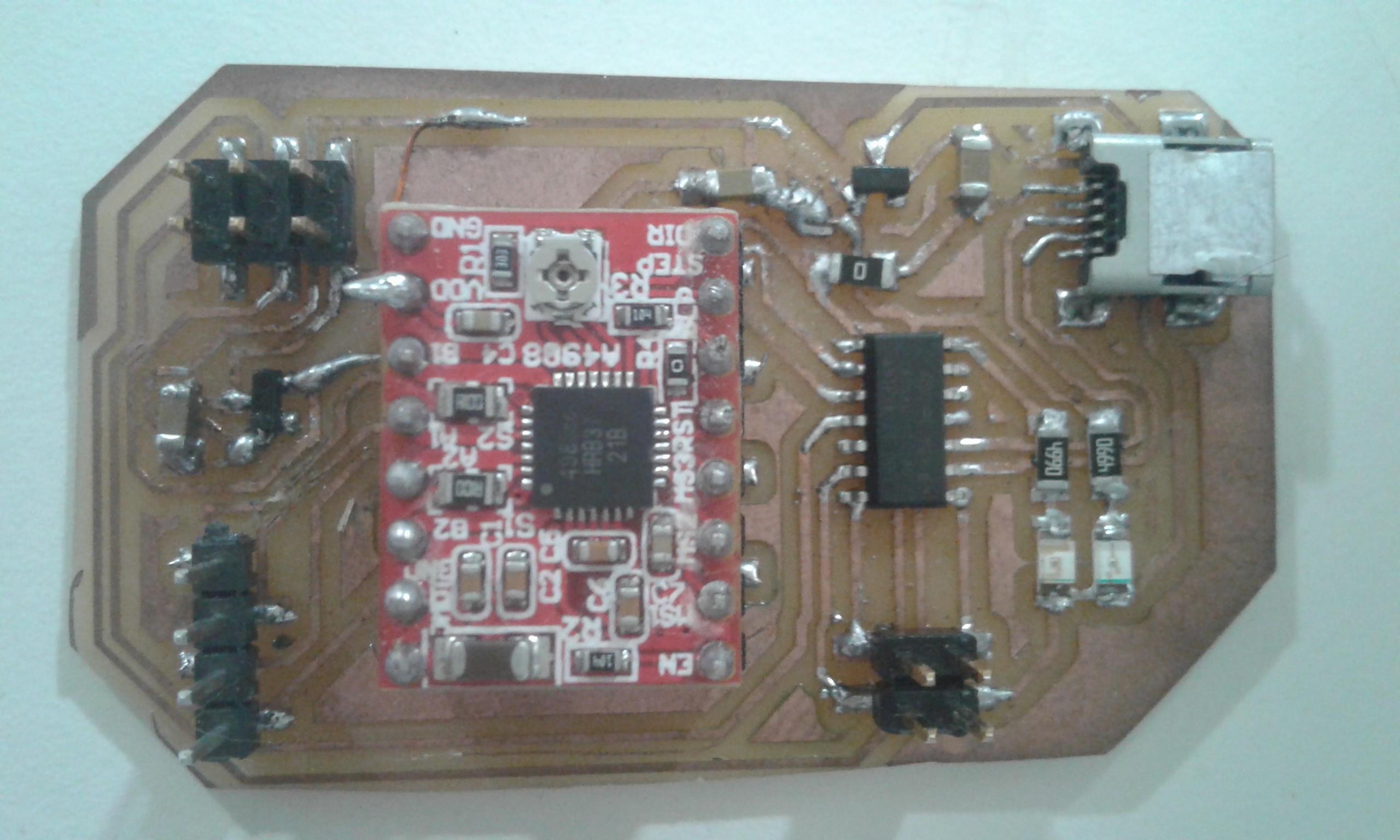
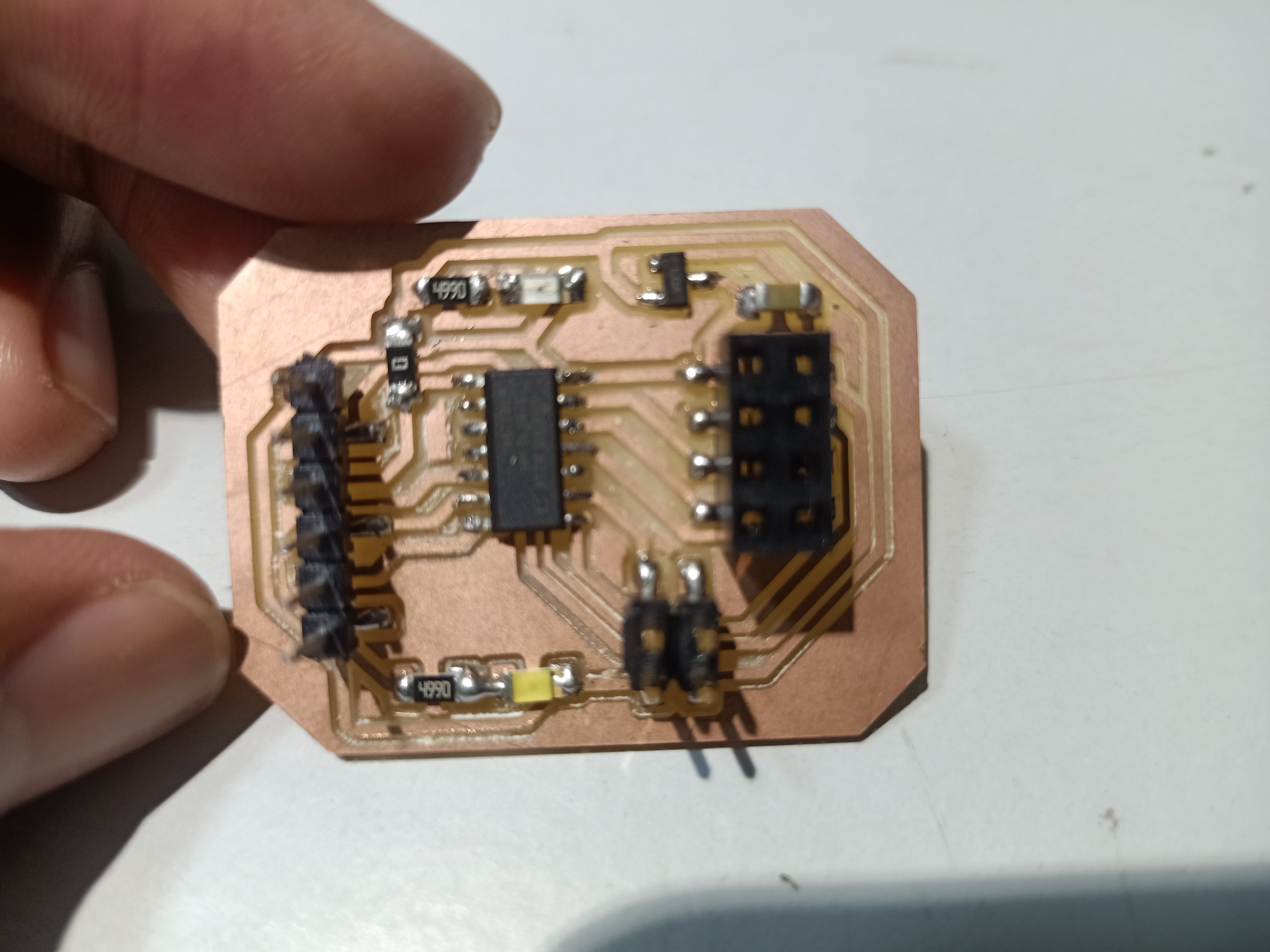
I made a board with SAMD11c14A including an A4988 stepper-motor controller.
But my board had a lot of problems. I studied how to troubleshoot a PCB.
- when connecting to power, the voltage regulator becomes hot. It was because of output of 2 voltage regulators are connected directly Then I removed VBUS of USB connector and cut the trace.
- VCC and Ground are shortcircuited
I removed each small component and I checked the shortcircuit. But I couln’t solve the problem. At last I removed SAMD11C IC and checked.
The VCC pin and GND pin of the IC was internally shorted. - After programming the micro controller, The stepper didn’t work.
The reason was:
- I didn’t give connection for VCC of A4988.
- I didn’t connected SLEEP and RESET togather.
At last, my board became ready.
After setting the boards, I programmed the board, but I noticed some mistakes. I couldn’t troubleshoot them. Due to lack of time I decided to change my assignment into another communication protocol.
NRF module.
What is nRF?
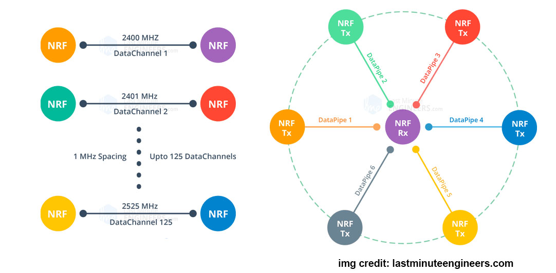
The NRF24L01 is a wireless transceiver RF module, where each module can send and receive data. Since it operates on the 2.4 GHz ISM band, the technology is approved for engineering applications in almost all countries. This module can cover 100 meters (200 feet) when operated efficiently, making it suitable for wireless remote control projects.
The NRF24L01 module is powered by 3.3 Volts, so it can be easily used in both 3.2 Volts and 5 Volts systems.
Each module has an address range of 125 to communicate with the other 6 modules and also allows several wireless units to communicate with each other in a specified location. Therefore, mesh and other types of networks use this module.
nRF24L01+ Module Pinout
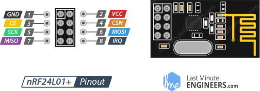
GND Connect to ground
VCC- 3.3 V
CE (Chip Enable)- It is an active-high pin.
CSN (Chip Select Not)- It is an active-low pin and is normally kept HIGH. When this pin goes low, the nRF24L01 starts listening on its SPI port for data and processes it accordingly.
SCK (Serial Clock)- Accepts clock pulses provided by the SPI bus master.
MOSI (Master Out Slave In)- It is the SPI input to the nRF24L01.
MISO (Master In Slave Out)- It is the SPI output from the nRF24L01.
IRQ- It is an interrupt pin that can alert the master when new data is available to process.
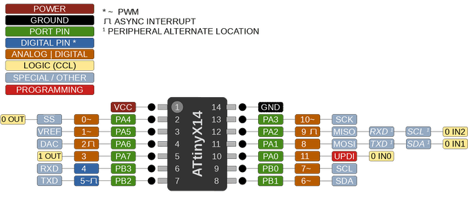
Pinout and Pinmap for ATtiny 1614
Making new circuit boards.
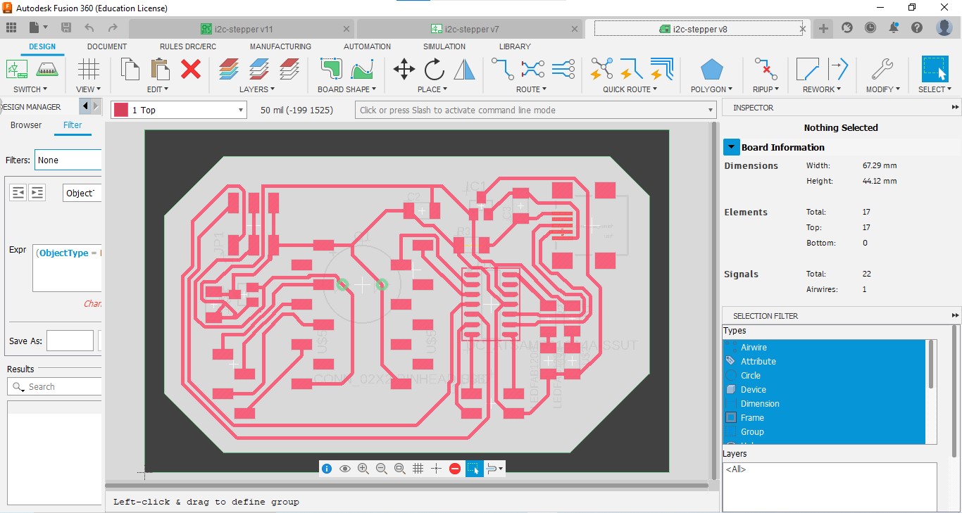
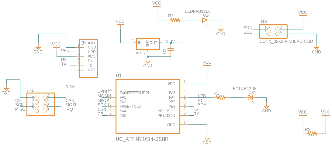
I made 2 boards which include the ATTINY1614 and the nRF24L01 module. I also leaved 2 pins(SDA and SCL) for I2C communication. We have made a number of boards till now. So this board was simple to made. I made boards in Fusion 360.
Schematic
PCB design
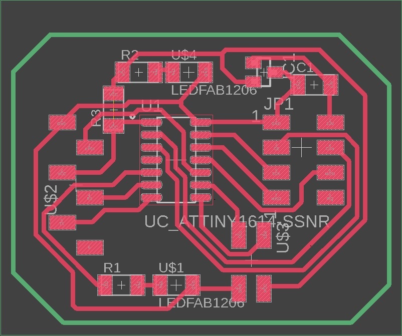
I made 2 same boards, One Transmitter and other one is Receiver.
Programming
After making boards, I connected nRF24L01+ modules to them, and confirm the working of modules in Arduino.
We need some libraries for program boards.
The SPI.h library handles the SPI communication while the nRF24L01.h and RF24.h control the module.
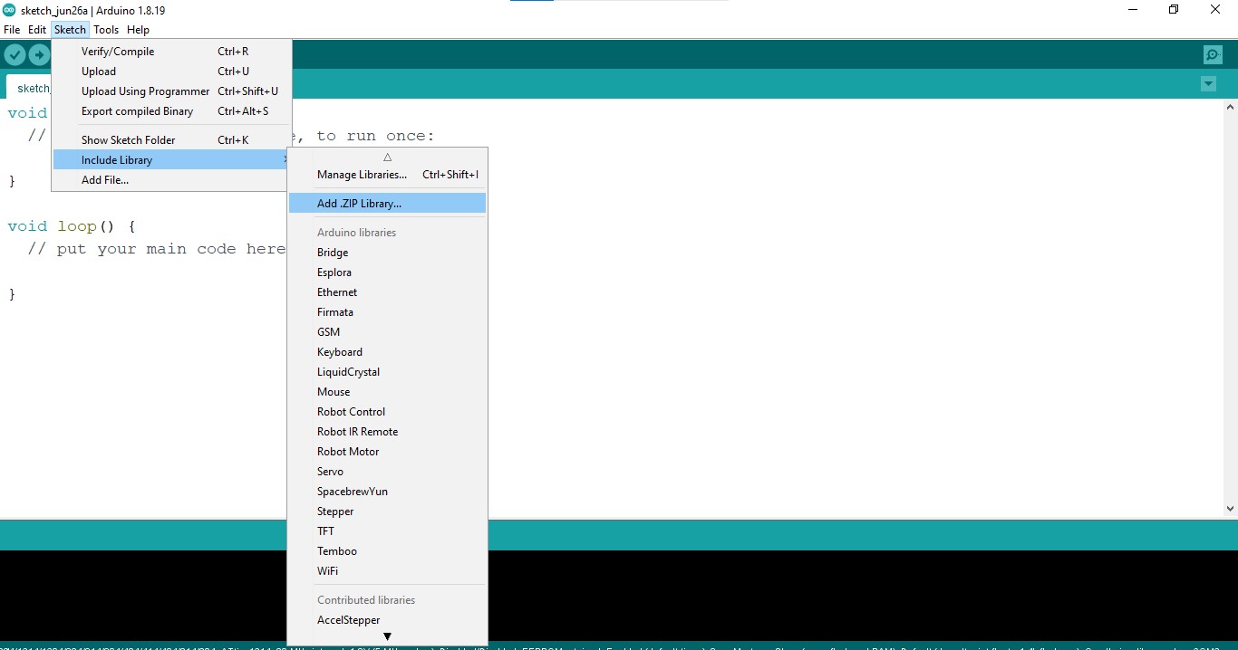
I downloaded these libraries from internet (Link here) and added to the Arduino IDE(By going to Sketch→ Include Library→ Add ZIP Library and added)
For testing the code I used the scanner example code provided by the downloaded library.
After conforming the working of boards, I programmed 2 boards.
Code for transmitter circuit
#include <SPI.h>
#include <nRF24L01.h>
#include <RF24.h>

RF24 radio(1, 0);  // CE, CSN

const byte address[6] = "00001";

void setup()
{
  radio.begin();

  radio.openWritingPipe(address);

  radio.stopListening();
}
void loop()
{
  const char text[] = "Hello World";
  radio.write(&text, sizeof(text));

  delay(1000);
}
Code for Reciever circuit
#include <SPI.h>
#include <nRF24L01.h>
#include <RF24.h>

RF24 radio(1, 0);  // CE, CSN

const byte address[6] = "00001";

void setup()
{
  while (!Serial);
    Serial.begin(9600);

  radio.begin();

  radio.openReadingPipe(0, address);

  radio.startListening();
}

void loop()
{
  //Read the data if available in buffer
  if (radio.available())
  {
    char text[32] = {0};
    radio.read(&text, sizeof(text));
    Serial.println(text);
  }
}
RF24 radio(1, 0); - Here we select our CE and CSN pins of our circuit.
const byte address[6] = "00001"; - This address represents the pipe address through which the two nRF24L01+ modules will communicate.
radio.begin(); - It is to initialize the radio object
openWritingPipe()-Function to set the transmitter address.
For detailed documentation (Link here)
After programming my boards using UPDI, I powered Transmitter with the USB port of Oscilloscope and the Reciever board connected to my laptop with UPDI serial.
Then I got the message text I sent from transmitter in Serial monitor of my laptop.
Bill of materials
| Part | Value | Device | Package | Description | AVAILABILITY | DESCRIPTION | MF | MP | PACKAGE | PRICE | PURCHASE-URL |
| C1 | 10 mF | CAP_UNPOLARIZEDFAB | C1206FAB | ||||||||
| IC1 | 3.3 V 100 mA | VR_REGULATOR-SOT23SOT23 | SOT23 | ||||||||
| JP1 | CONN_03X2-PINHEAD-SMD | 2X03SMD | PIN HEADER | ||||||||
| R1 | 499 ohm | R1206FAB | R1206FAB | Resistor (US Symbol) | |||||||
| R2 | 499 ohm | R1206FAB | R1206FAB | Resistor (US Symbol) | |||||||
| R3 | o ohm | R1206FAB | R1206FAB | Resistor (US Symbol) | |||||||
| U$1 | LEDFAB1206 blue | LEDFAB1206 | LED1206FAB | LED | |||||||
| U$2 | CONN_01X12_PRGRMR | CONN_01X12_PRGRMR | 1X12(2_ROW) | ||||||||
| U$3 | CONN_02X2-PINHEAD-SMD | CONN_02X2-PINHEAD-SMD | 2X02SMD | ||||||||
| U$4 | LEDFAB1206 red | LEDFAB1206 | LED1206FAB | LED | |||||||
| U1 | UC_ATTINY1614-SSNR | UC_ATTINY1614-SSNR | SOIC127P600X175-14N | 20MHz, SOIC, 85C, Green, 14 SOIC .150in T/R Check prices | In Stock | AVR tinyAVR™ 1, Functional Safety (FuSa) Microcontroller IC 8-Bit 20MHz 16KB (16K x 8) FLASH 14-SOIC | Microchip Technology | ATTINY1614-SSNR | None | None | https://pricing.snapeda.com/search/part/ATTINY1614-SSNR/?ref=eda |