Embedded Programming
Hero Shots
Click Here for Our Group Assignment
Hero Video 😀
File Downloads From This Week
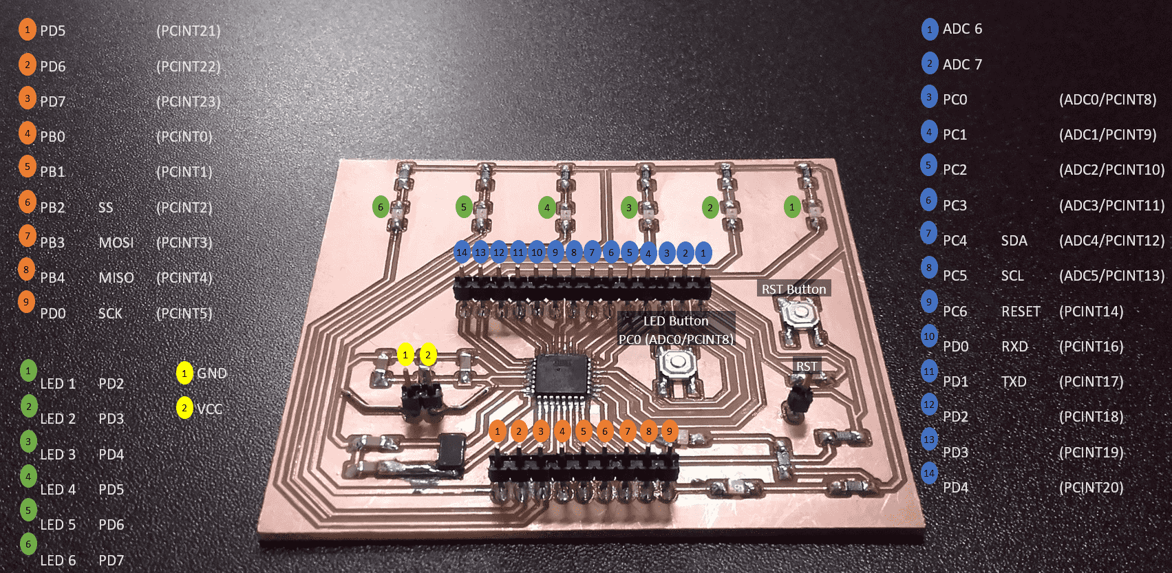
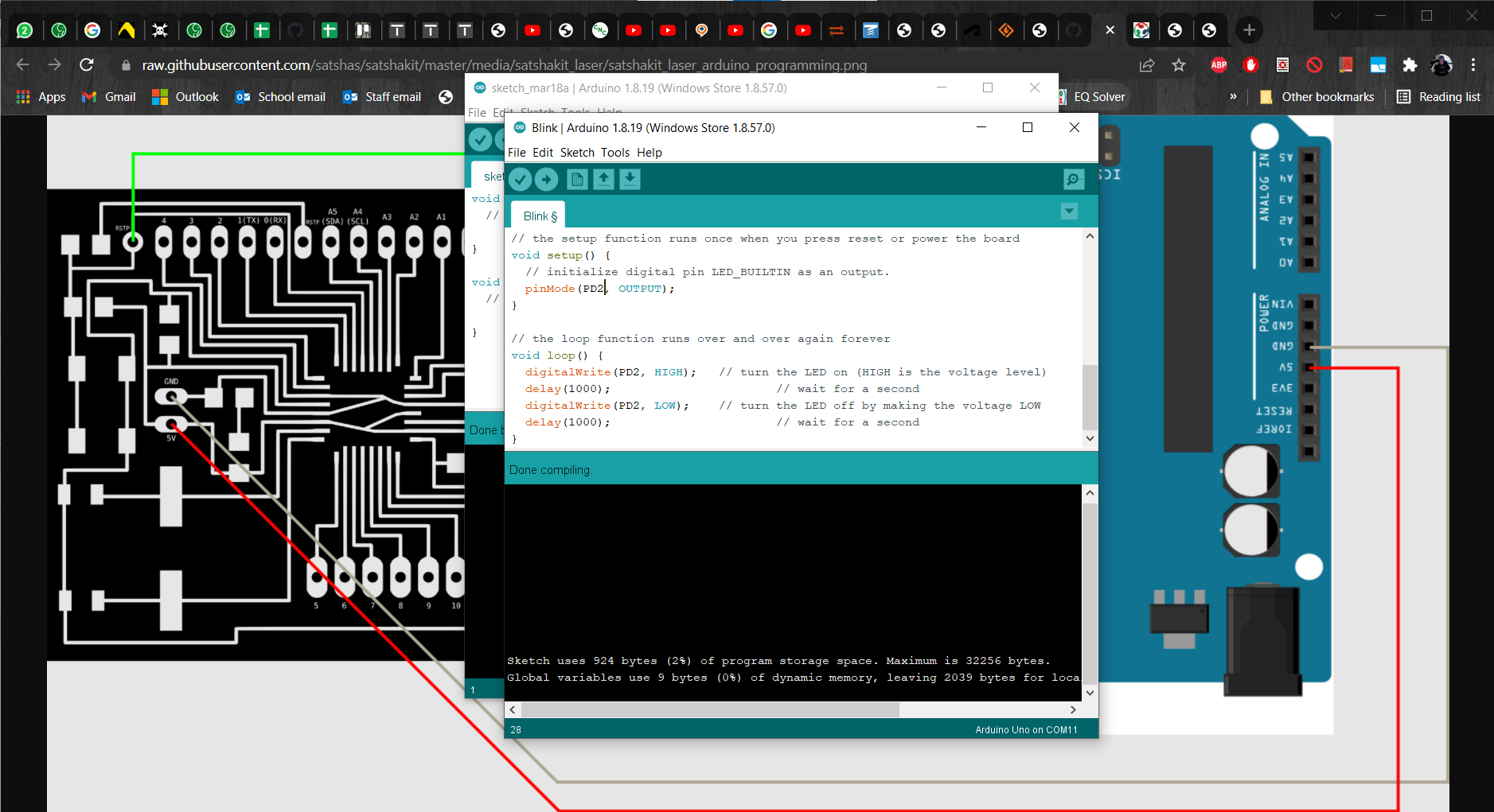
Pinout for My Satshakit
Initial Reaction
Here we go again lol. I am a mechanical engineer so I have had a few very basic coding classes, but those were focused on mechanics and structural analyses, and they were mostly in Matlab. This will be my first experience with embedded programming of any kind. The lecture with Neil this week felt like a water hose of information. Architectures, memory, peripherals, AVR, ISP, UPDI...the list just kept going and going and I was feeling more and more lost with the big picture. I think I need to focus on the parts that will be relevant for my assignments, because otherwise, I think my brain might explode. Speaking of assignments, the individual assignment is to read the data sheet for our microcontrollers and then to use the programmer that we made in Electronics Production Week to program the PCB that we made during the Electronics Design Week to do something. The group assignment is to compare the performance and development workflows for different architectures.
After Local Workshop
In the local workshop this week, Marcello walked us through some of the workflow for this kind of programming. He showed us the Arduino IDE and a bit of how to use the data sheet from the microcontroller to find the necessary information about the pins and how to access them. In the Arduino IDE, he also showed us how to open various libraries and how to access example code files such as the Blink program. Fortunately for me, he used an ATmega328P for his example so I was able to learn quite a bit that would help me with my own board, even though I felt lost most of the time and asked at least a dozen of what I am sure were silly questions. Toward the end of the session, we saw AVR in action and were able to compare the workflow and the memory consumption differences on the chip.
Programming My Board
Using an Arduino as an ISP
Figuring Out My Pinout
Unfortunately, I was so nearly overwhelmed during the electronics design week that I didn't pay much attention to, or make note of, the pinout for my shiny new board...due to this oversight, I had to begin by sorting through my schematic and my blueprint as well as the pinout and the datasheet of the ATmega328P to figure out what I put where. It took a while, but I am actually really pleased with the results and I am glad I took the time to do it.
Connecting to My Programmer
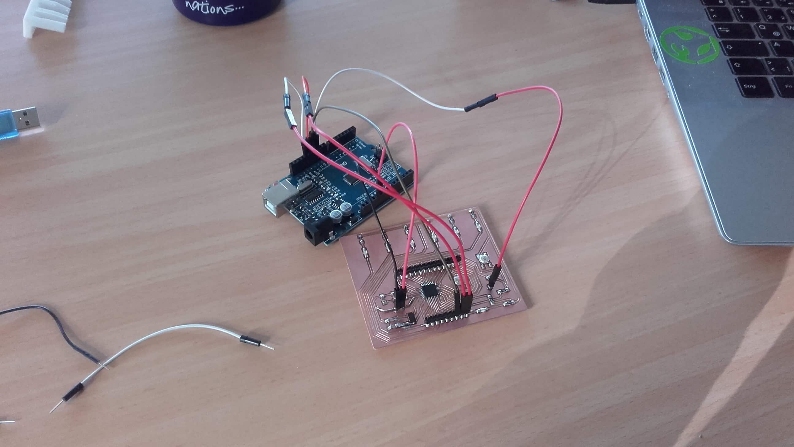
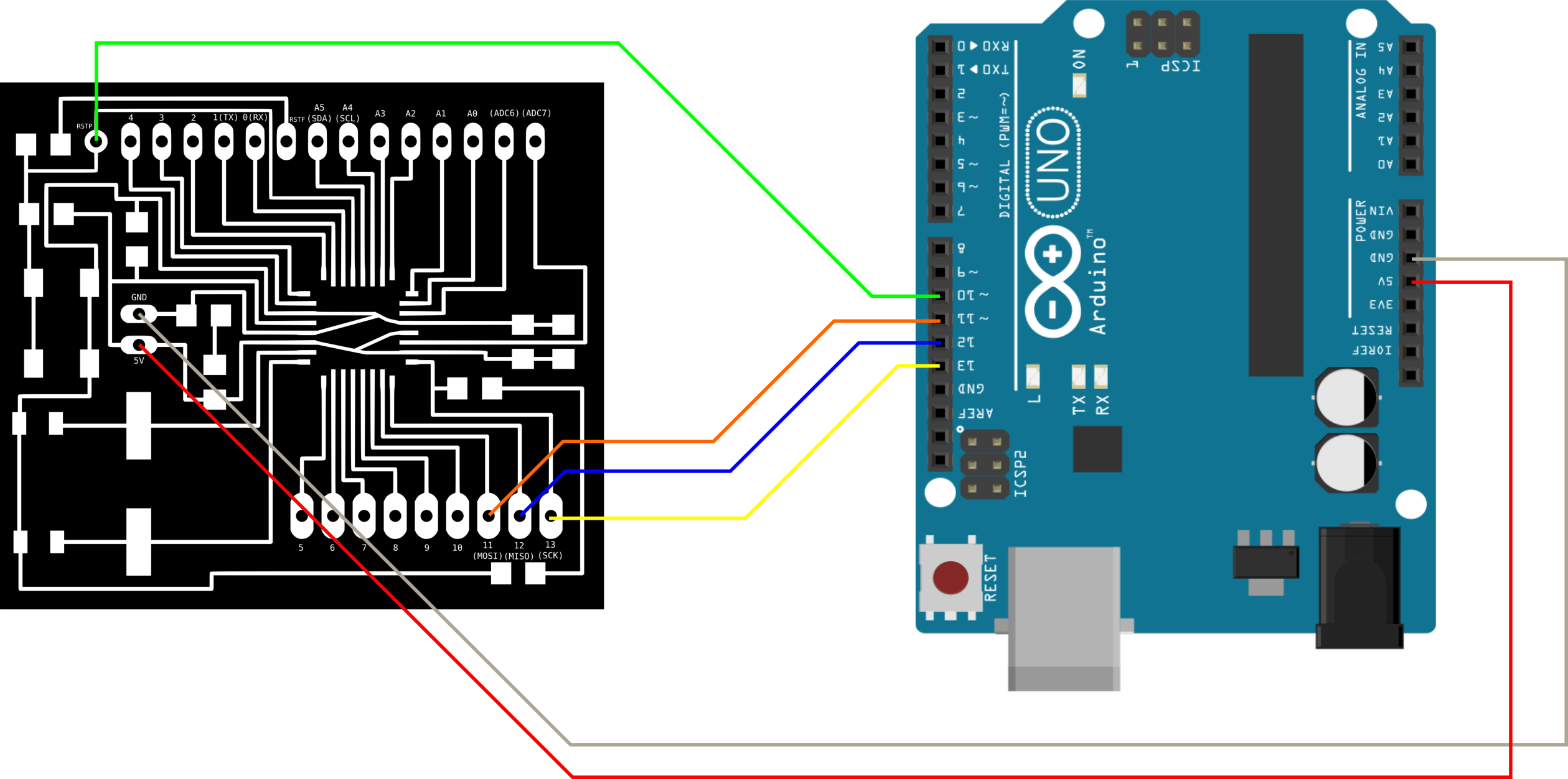
For the Electronics Production week, I made a FT230x-UPDI, so I don't have an ISP programmer at the moment. Thus, for this assignment, I decided to use an Arduino Uno as my ISP programmer. I started by connecting the Arduino to my board according to the connection schema from the Satshakit readme.
Arduino as ISP
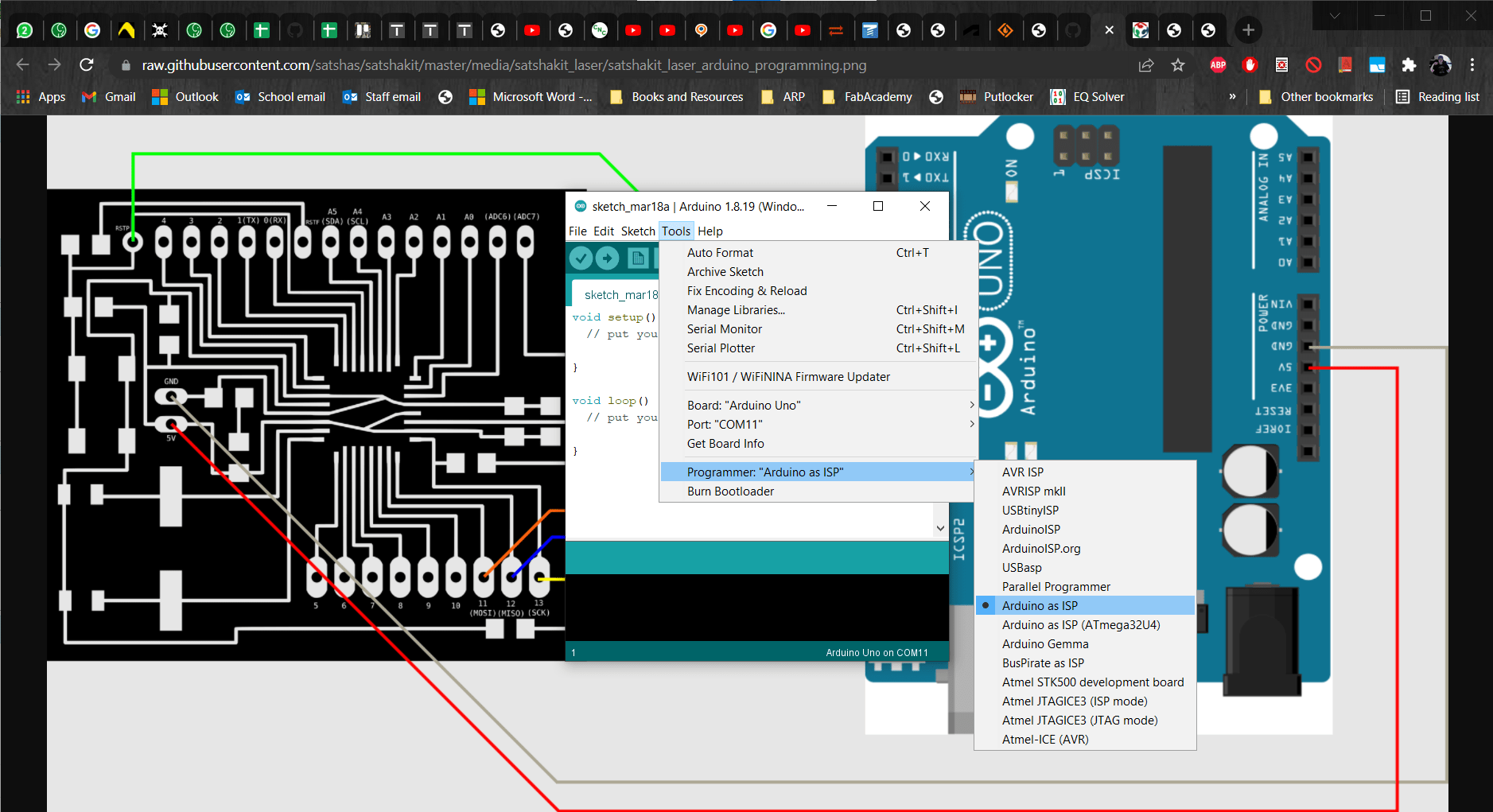
I opened the Arduino IDE. Then from the Tools menu, I chose the Uno as my board and selected Arduino as ISP for my programmer.
Compile
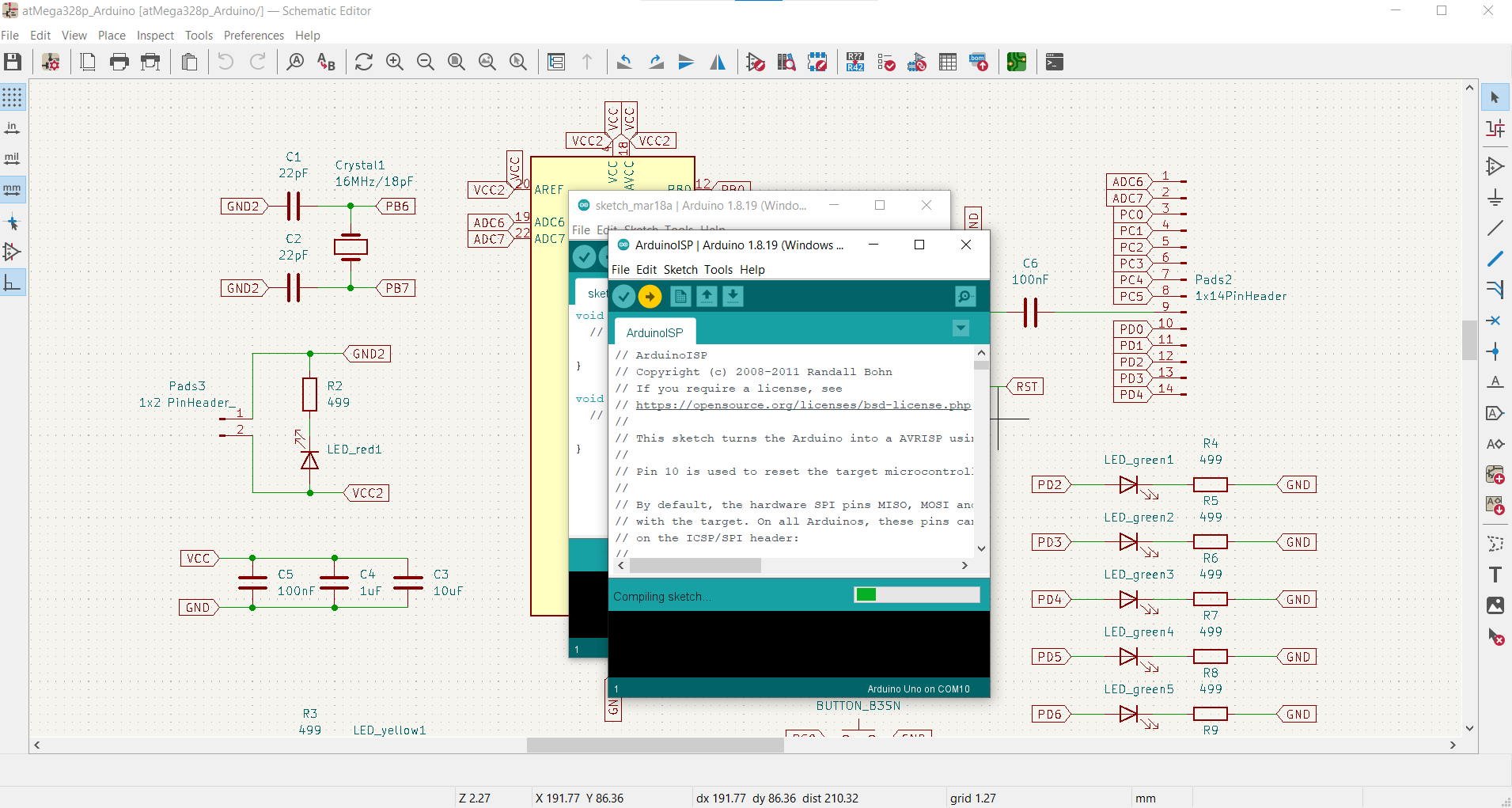
Next, I compiled the sketch...
Burn Bootloader
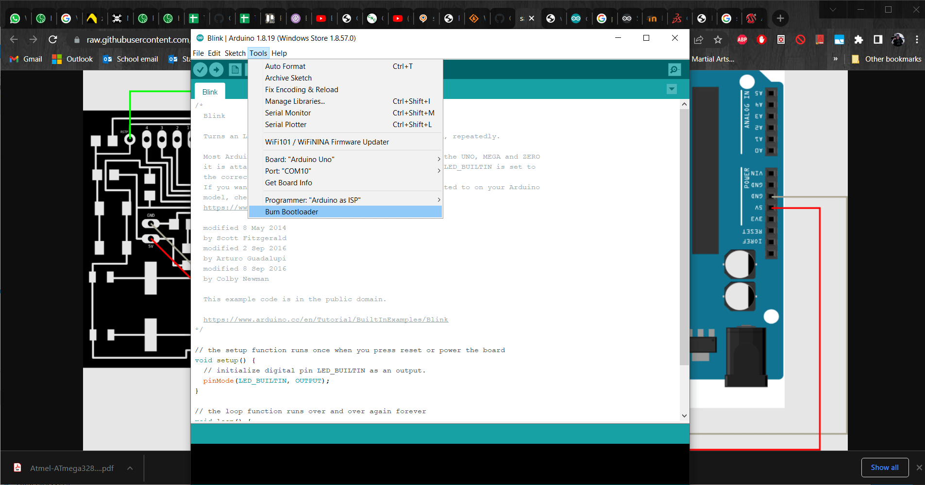
...and then selected Burn Bootloader from the Tools menu.
Doh!
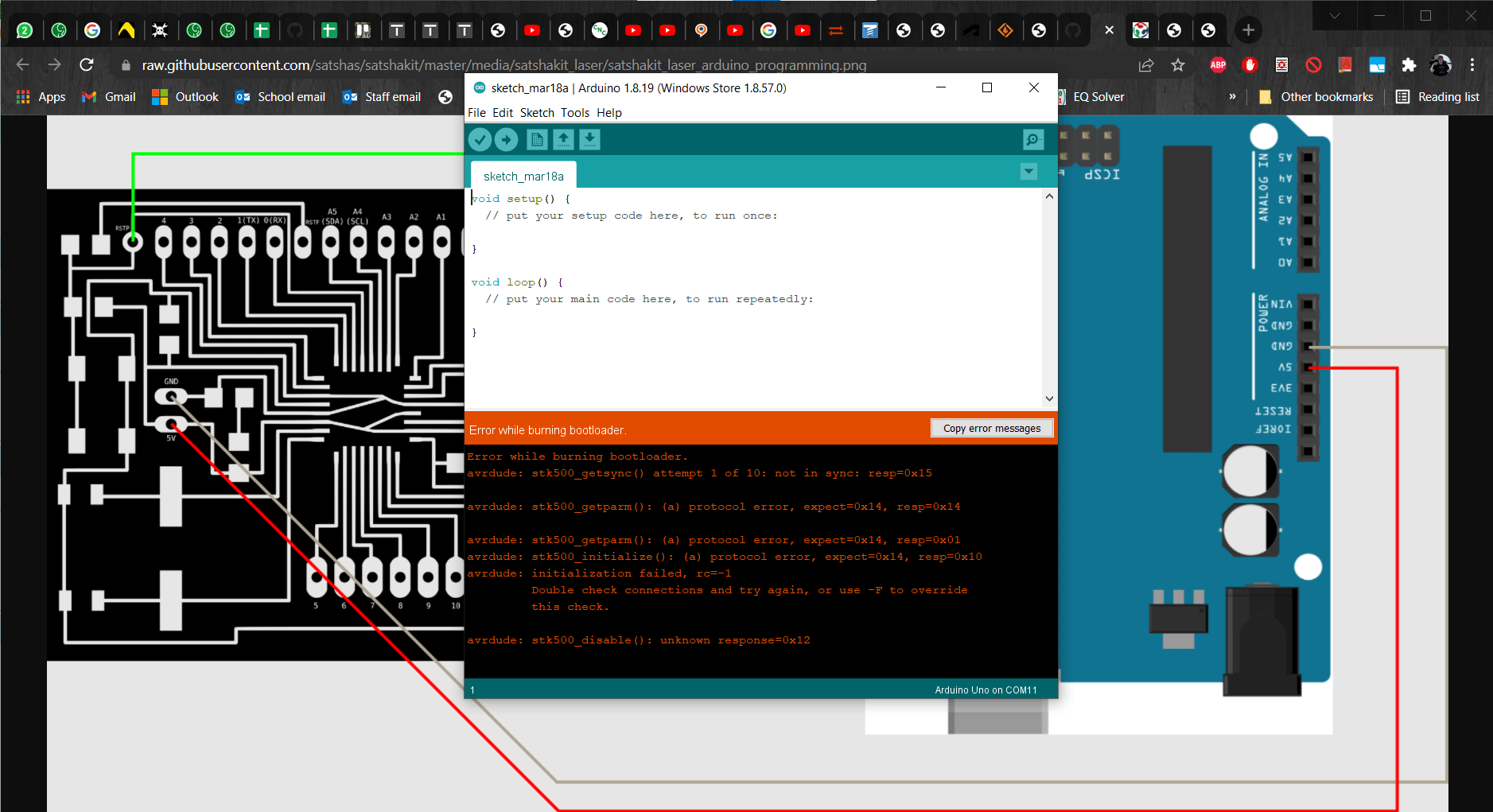
This is where things started going wrong.
Crisis Management
This error crushed my soul! I was already scared that I would have problems with the bootloader since I used a 20 MHz crystal instead of the 16 MHz one called for in the BoM. I knew from the Electrical Characteristics in the datasheet that it wouldn't cause any problems with the microcontroller as long as I give it 4.5-5.5 V, but I could not find anything confirming that it could work with the bootloader. So I set out to investigate what could be going wrong. I spent tons of time researching what the crystal and bootloader actually DO and couldn't find any reason why these two should be incompatible. Then I spent more time retesting all the connections on my board to make sure I hadn't broken a solder joint or something like that. They were all fine, so then I though maybe I had screwed up the schematic or blueprint somehow and started rechecking all of the logic in my design, all the while becoming increasingly panicked about the amount of work I was going to have to redo. After losing an entire day troubleshooting, Roland suggested that maybe I should test the jumper wires I was using to connect the Arduino to my board...
The Culprit
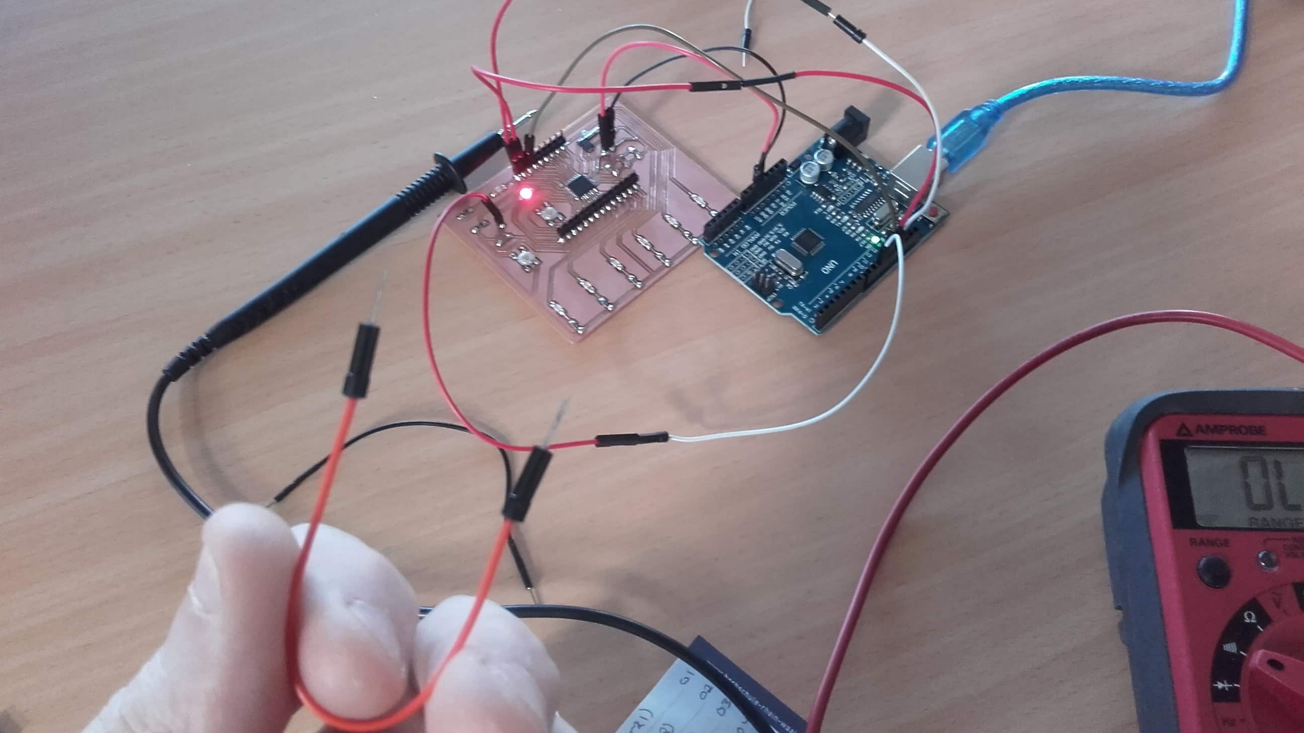
...and of course, this one little stupid wire was the problem. I felt very stupid for not checking the most OBVIOUS thing first, but it just didn't occur to me since I was already anticipating potential problems with the bootloader and things just escalated from there.
Done Burning Bootloader
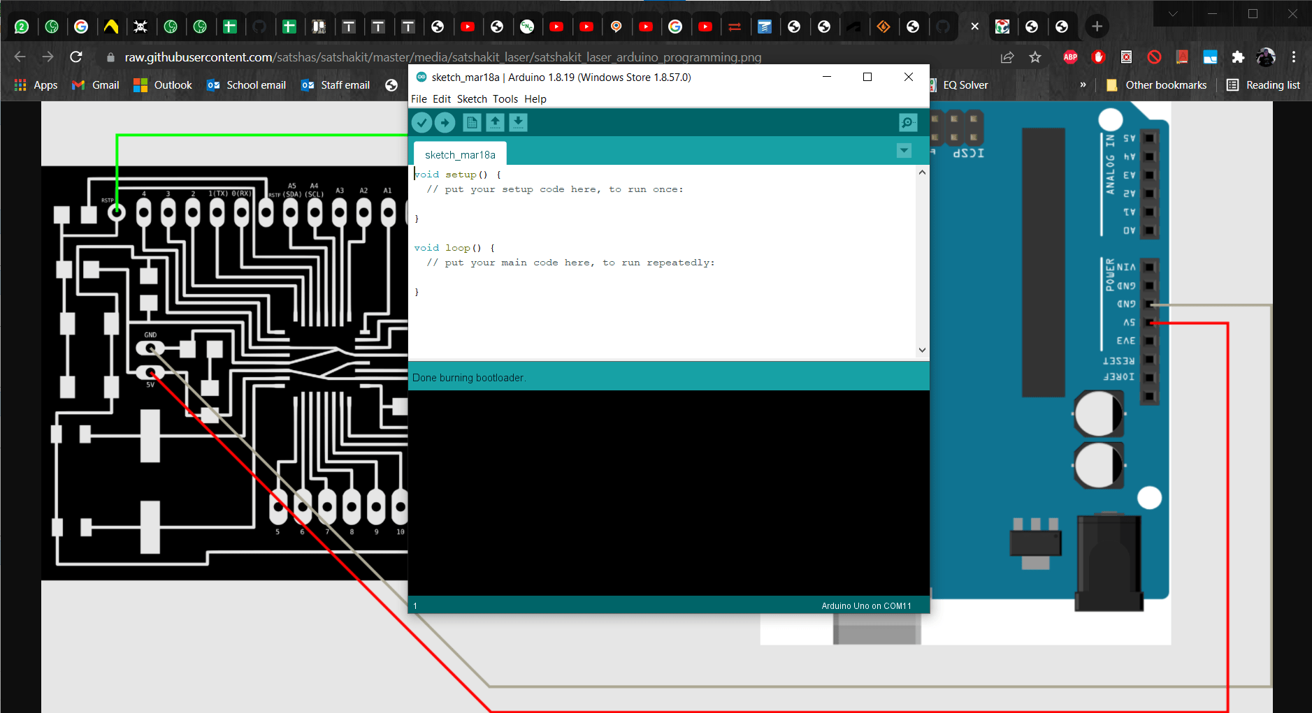
I replaced the wire and tried burning the bootloader again - success!
Upload Using Programmer
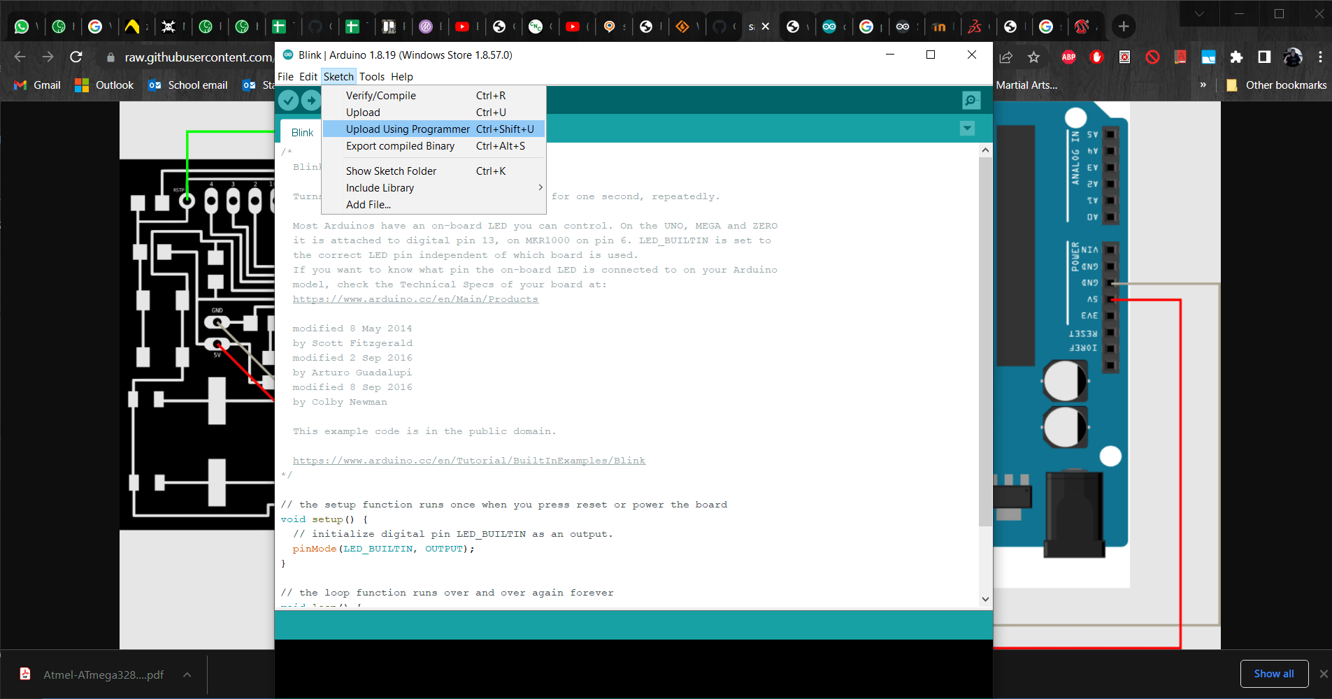
Then I opened up the Blink example program and uploaded it using the Upload Using Programmer tool from the Sketch menu (not using File/Upload, which would have uploaded it to the Uno instead).
It's ALIIIIVE
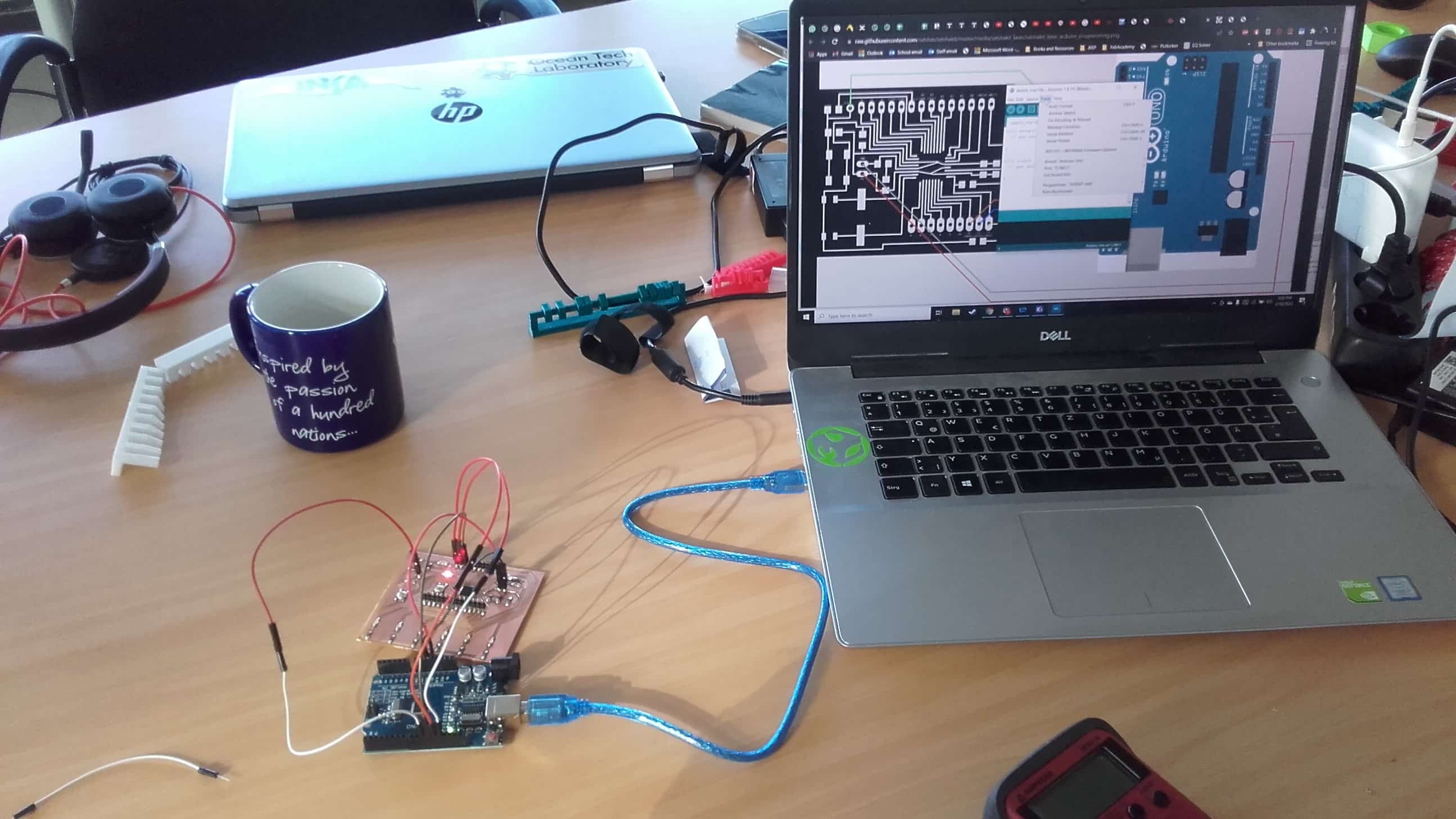
The lights on both boards flashed for a couple seconds and then my board came to life for the first time. This was exhilarating for me! I've always been afraid of electronics and programming and here was a thing I made from scratch that is the lovechild of them both. Of course I take no credit for any of it (other than maybe my hacky soldering job), but I was very proud that it worked.
Now for LEDs
So then I set out to change the Blink program around to light up my green LEDs as well. In the setup, I used pinmode to change the input to my button and the outputs to my LEDs.
Loop
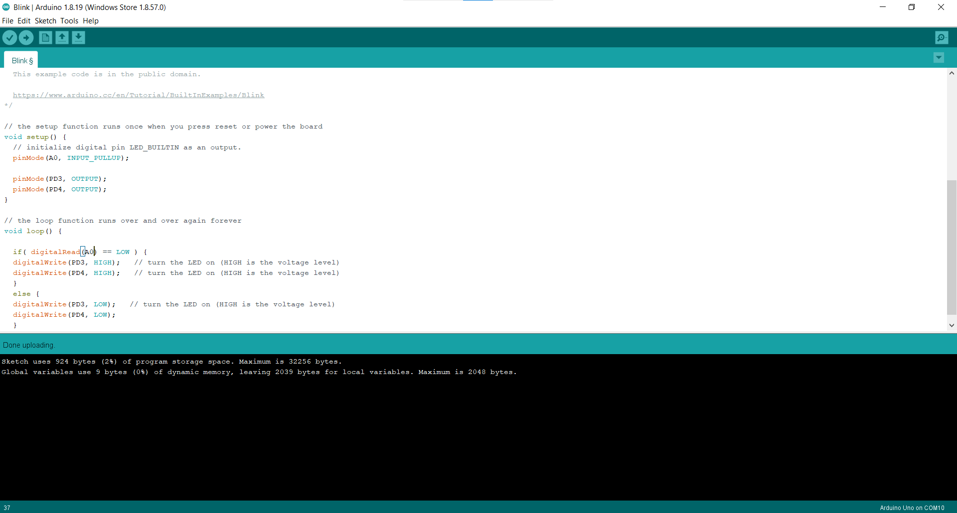
Then in the loop, I used digitalread to read the state of the button and digitalwrite to assign new states to the LEDs based on the state of the button.
Pull-up Resistor
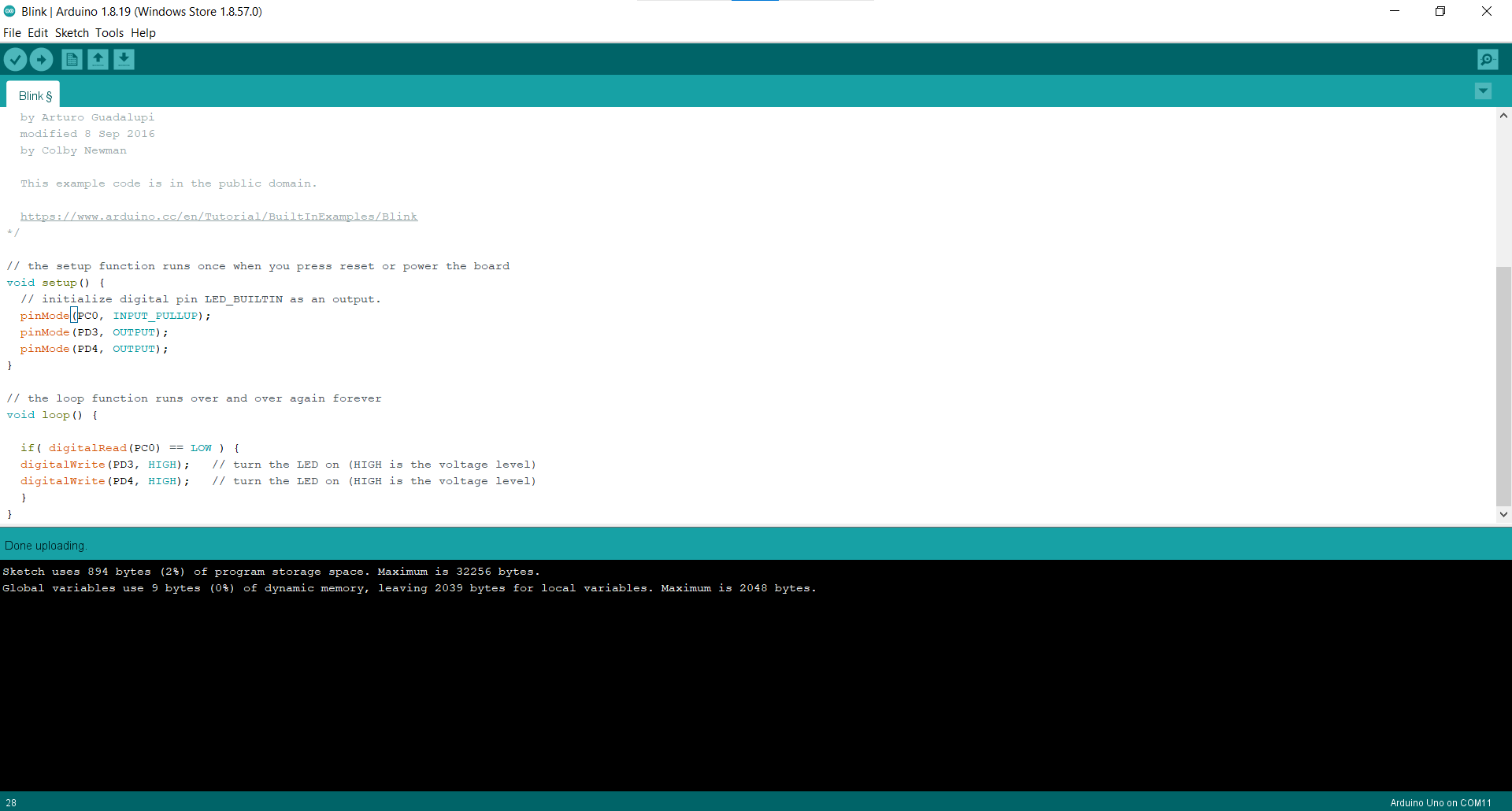
Since I now wanted to be able to read the state of my button, I added a pull-up resistor to the input in the setup.
Woohoo!
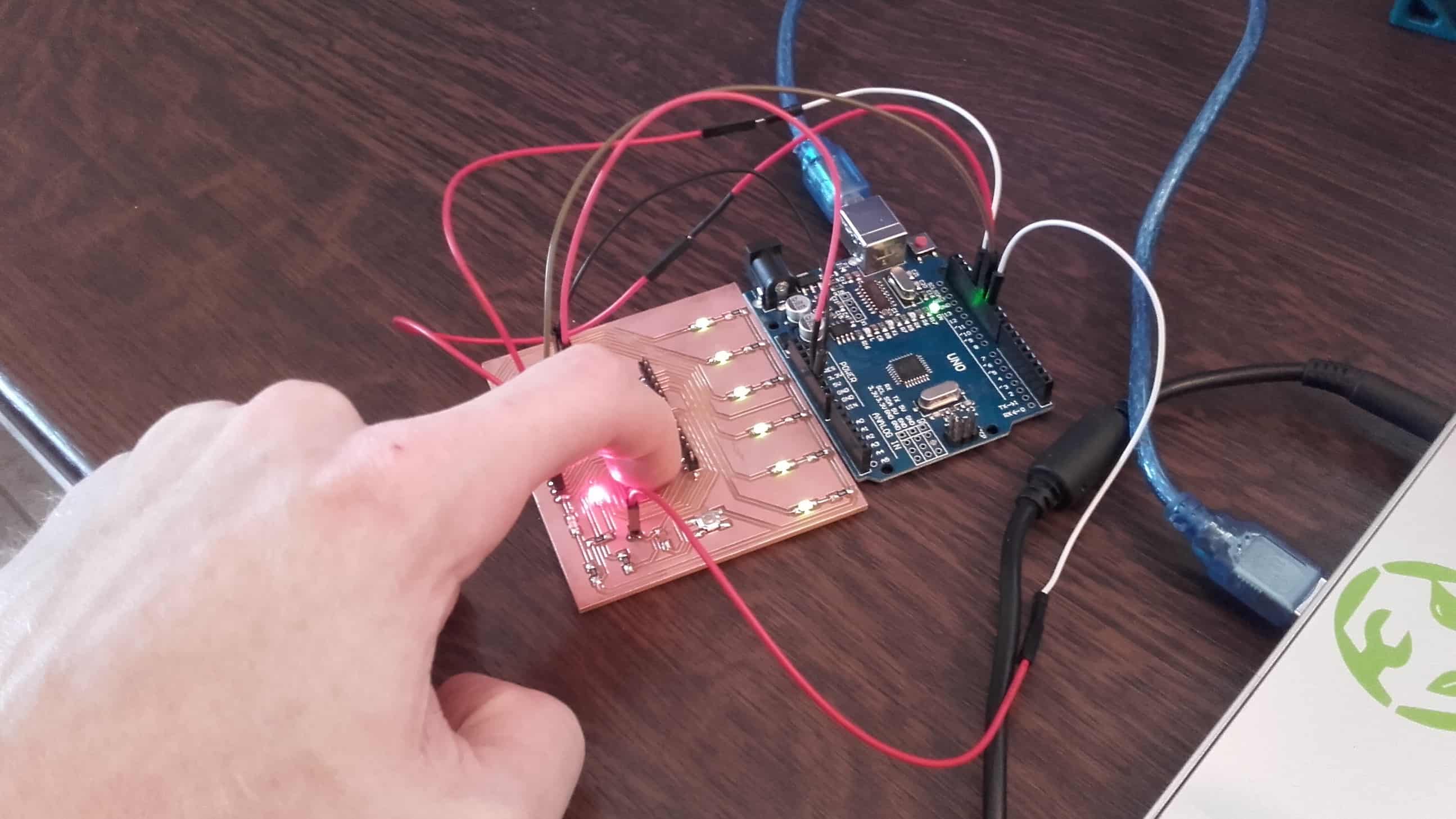
I uploaded the sketch to my board again...and it worked! Now, when I pressed the button, all my LEDs light up as well! 😎
My Submission
Button to Switch
I didn't want to have to hold the button down so I set out how to make it act like a switch in my program.
State Changes
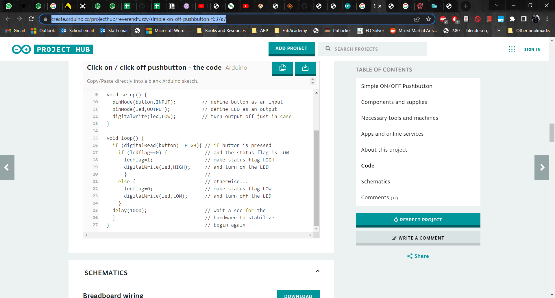
I got lost in a few threads, but eventually stumbled across a helpful project on ProjectHub that suggested using variables as flags. I tried to figure it out and I got pretty close, but it was acting kind of erratic. Like, sometimes the lights would only flash and sometimes they would come on for a second or more before turning off, and other times they would stay on when I pushed the button. Fortunately Marcello was in the lab that day so he explained to me that the state is being checked at some high frequency and the precision of my finger to press the button was insufficient to get a reliable output. Of course this made perfect sense, it just hadn't occurred to me before he said it. He advised me to add a couple more variables and a loop that was dependent on two conditions.
A Few More Lines of Code
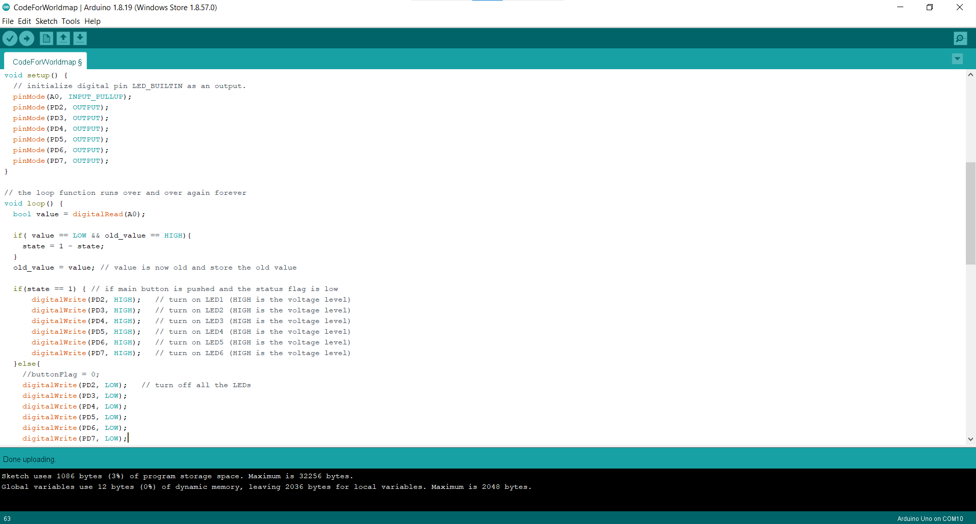
This little bit of help was all I needed and the program finally worked.
Final
Now, when I press the button, all my LEDs come on and stay on until the button is pressed again.