Electronics Production
Hero Shots
Click Here for Our Group Assignment
New Programmer
File Downloads From This Week
- Original PNG of traces
- Original PNG of cutout
- Traces gcode for Genmitsu
- Cutout gcode for Genmitsu
- Traces gcode for Roland
- Cutout gcode for Roland
$90 Adapter
Initial Reaction
This course is definitely coming in waves. Once again, I have been introduced to an entirely new world for me--the world of electronics production. This week, we are to make circuit boards for programming micro-controllers. I don't really know what that means, but Niel has assured us that understanding the electronics we are producing is not necessary at this point. For now, we are simply focusing on the production. Fortunately, I know something about production. I am new to these materials and I am relatively new to CNC machining, or any machining on such a tiny scale for that matter, but I am really looking forward to getting into it at the lab tomorrow.
After Local Workshop
Once again, the local workshop was tremendously useful! Ahmed gave us a detailed tour of the workflow that Niel recommended yesterday (PNG to Mods to CNC mill), as well as a quick overview of his own usual workflow using Gimp and Fusion 360. We also learned how to set up the mill, how to change tools, how to prepare the circuit board and sacrificial material, proper safety procedures, and even a handful of quality control measures for ensuring that the finished product is functional and structurally sound. Then, he gave us a quick run-through about soldering. This was material that was mostly covered by Niel in class and during the presentation in the bootcamp week, but it was still nice to have a refresher course and to be able to ask questions. I'm excited to get started.
Getting Set Up
Unboxing the Roland
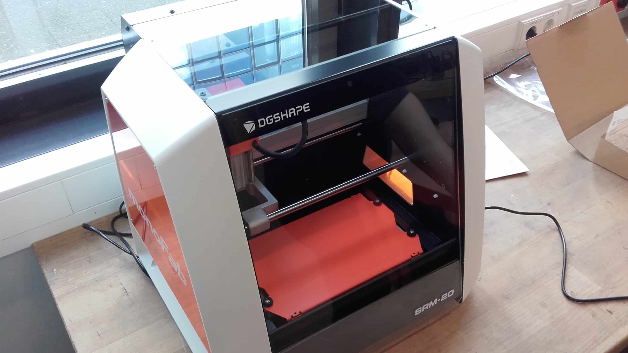
Our lab is borrowing a brand new monoFab SRM-20. It was looking sweet and had that fresh out-of-the-box smell.
Powered and Connected
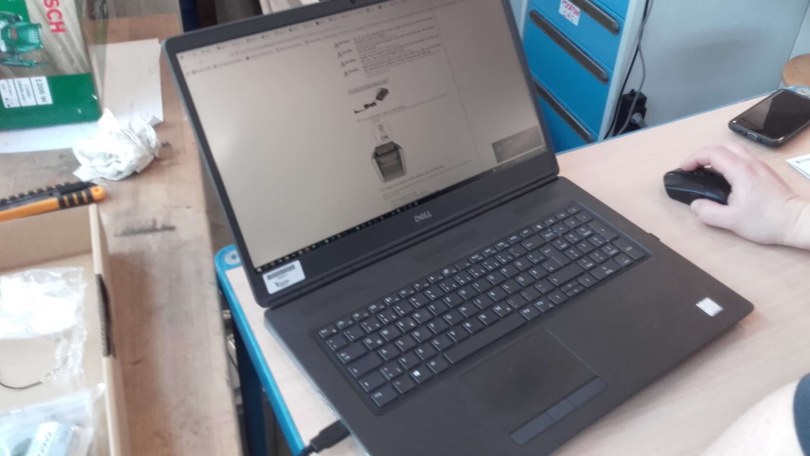
We got it powered up and connected to make our way through the software installation.
Driver
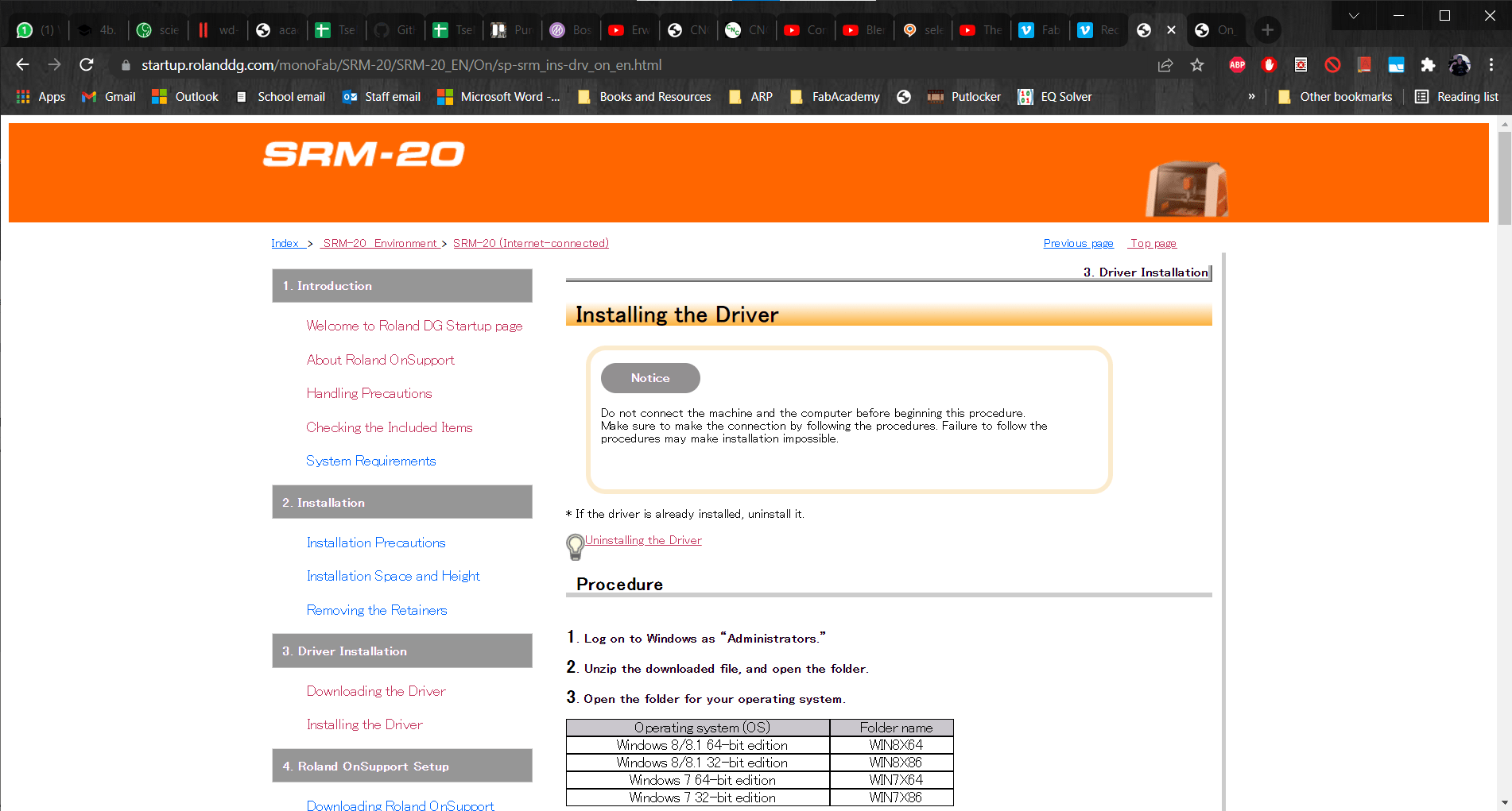
I attempted to download the driver, but at this point I got an error saying I already had a driver (done automatically when I plugged in the USB cable) and that it would have to be removed before downloading again. 🤨
Uninstalling Before Reinstalling
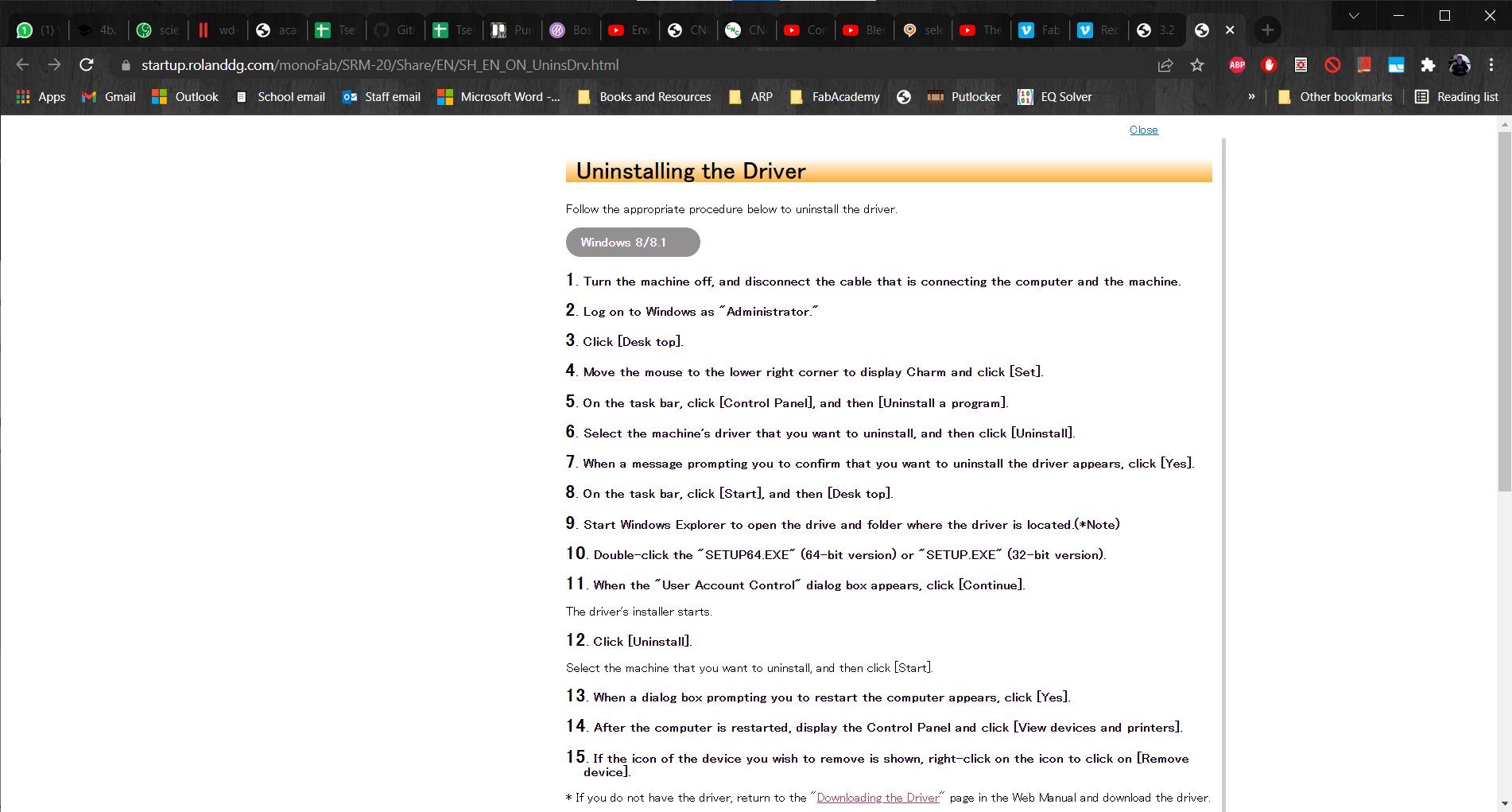
So I uninstalled and then reinstalled, as directed.
Driver Again
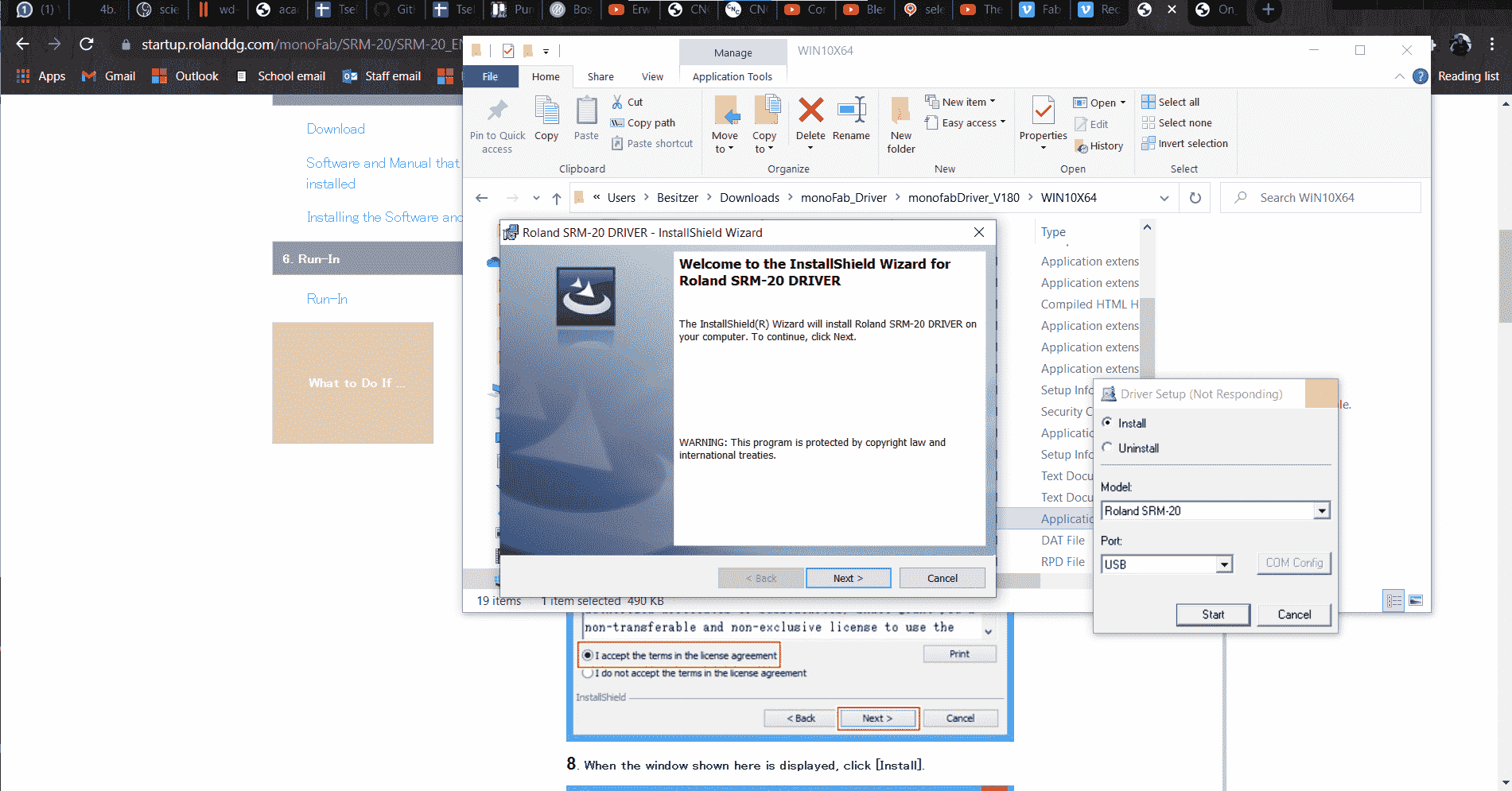
After the driver successfully installed...
Seriously?!
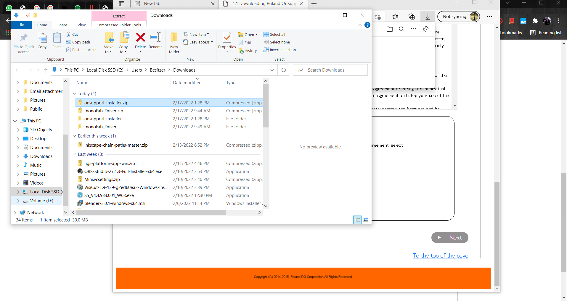
...then we only had to download and install 7 more software packages to be all set up.
Finally Ready to Go
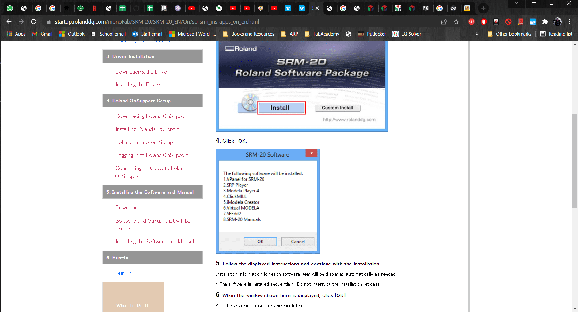
But eventually we were all set up and ready to roll...or so we thought. As it turns out, the Roland only comes with a 6mm tool holder that holds the tool with a set screw, not a collet like every other mill on Earth.
NOT!
And of course, all of our tools have a 1/8" shank. We searched online, but the 1/8" tool holder (they call it a collet, but that doesn't make it one) from Roland is over 80 bucks, and we don't have time to wait for it anyway.
Plan B, C and D
Big CNC Machine
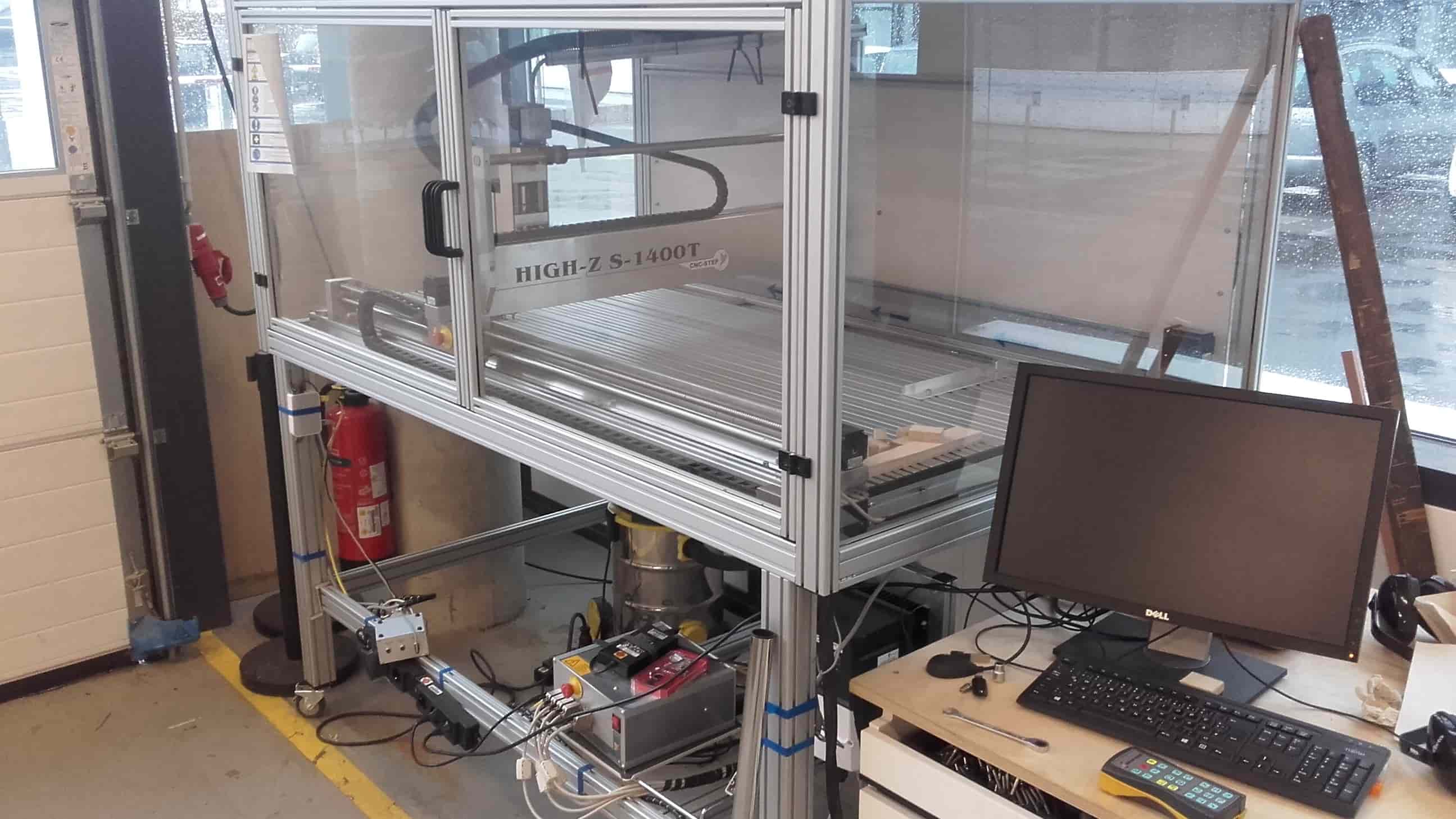
Not accepting defeat, we got busy. Roland decided to see if he could get the big CNC machine set up to cut PCBs.
Genmitsu
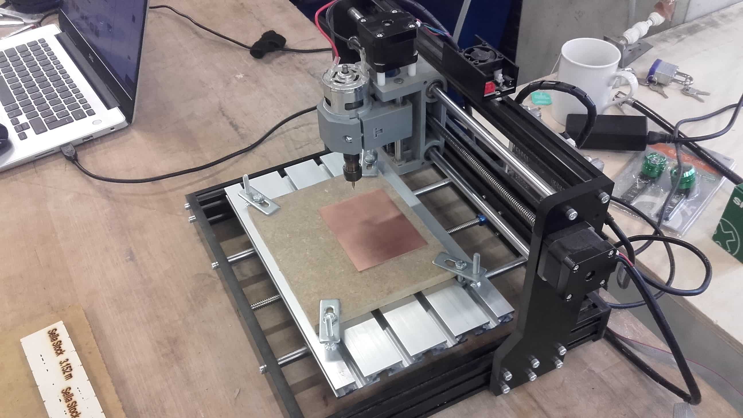
And Cello, dusted off the Genmitsu that hasn't been used in over a year to see if he could get it running again.
Adapter for the Roland
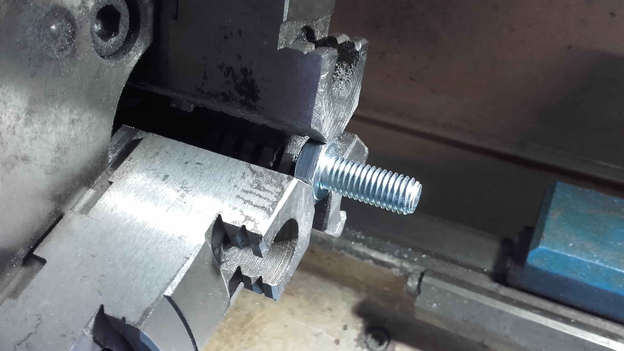
While I took on the mission of conventionally machining an adapter that would make the Roland usable without spending more money or waiting. I began by popping an M12 x 20 hex bolt into the lathe.
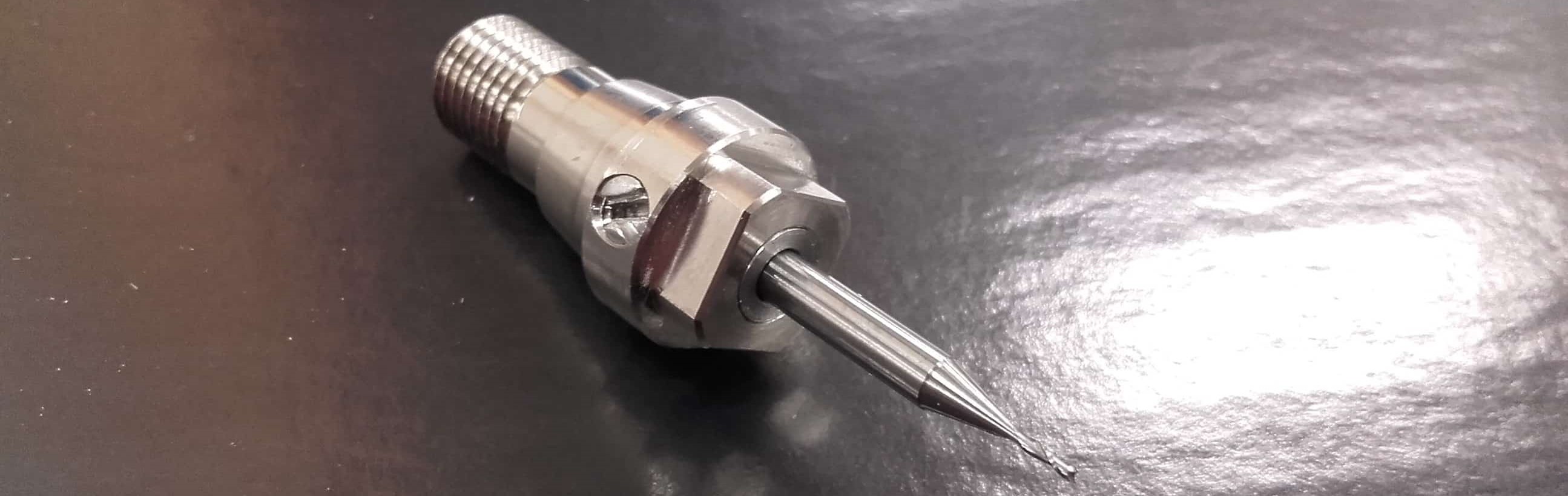
Basic Geometry
I wanted a slight interference fit between the outer diameter and the existing tool holder (5.96mm) and a transition or very slight clearance fit for the inner diameter and the tool (3.175 mm), so I carefully took the workpiece down to an OD of 6.05mm and ID of 3.18mm.
To the Milling Machine
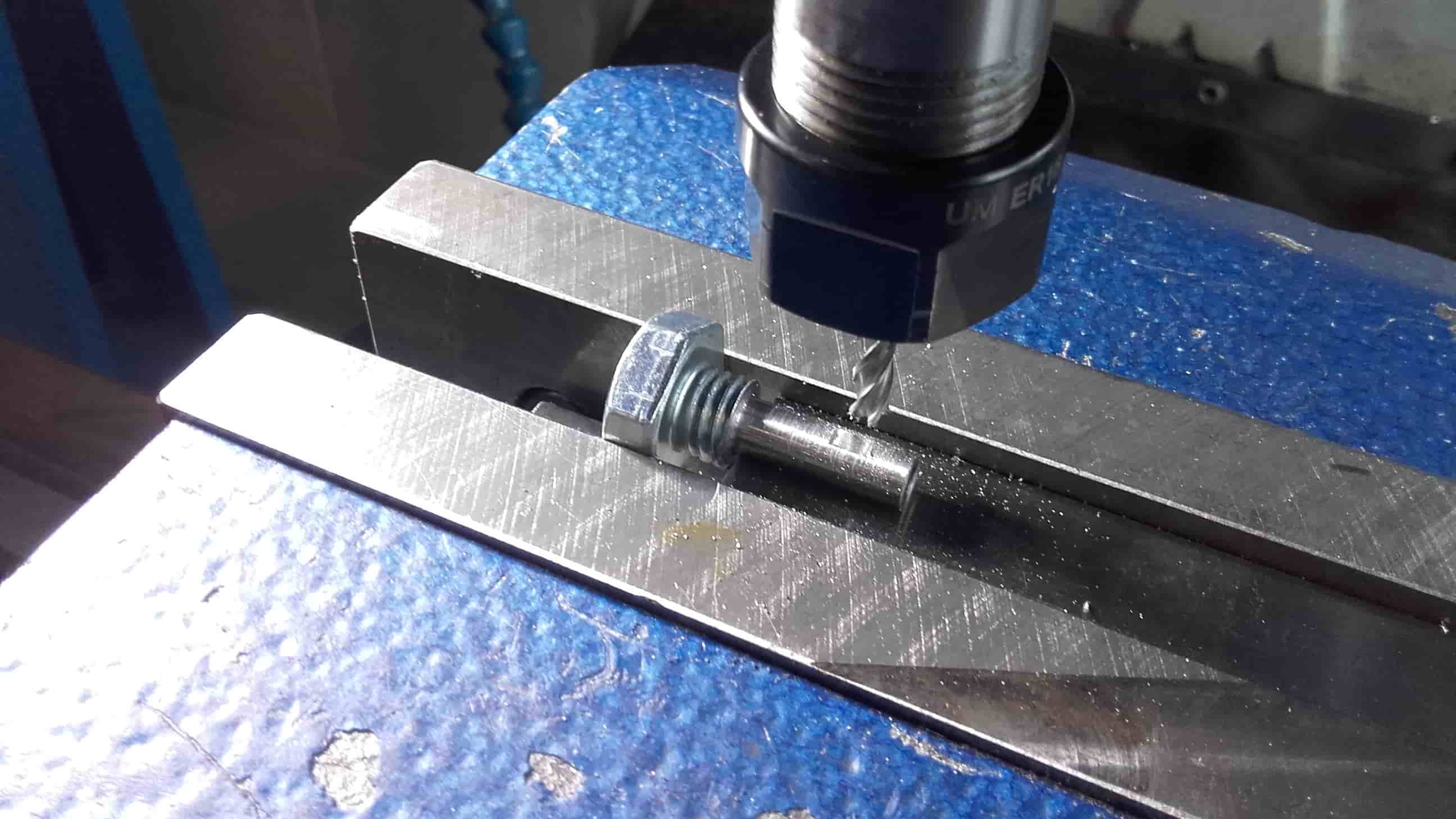
Then I mounted the piece into the mill and I made a flat spot with a 4mm endmill.
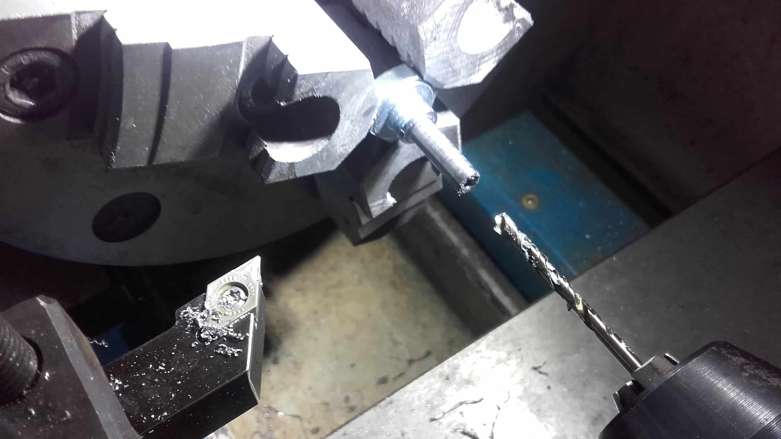
Blind Hole
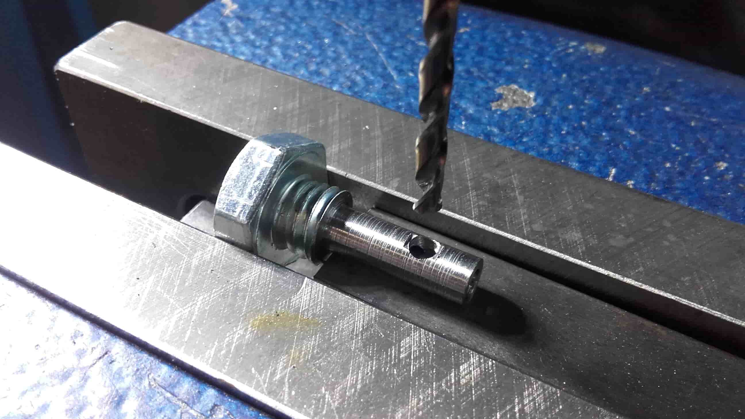
Then I made a hole for the set screw from the tool holder to pass through the new adapter to clamp the tool and then cut the new finished part from the bolt head.
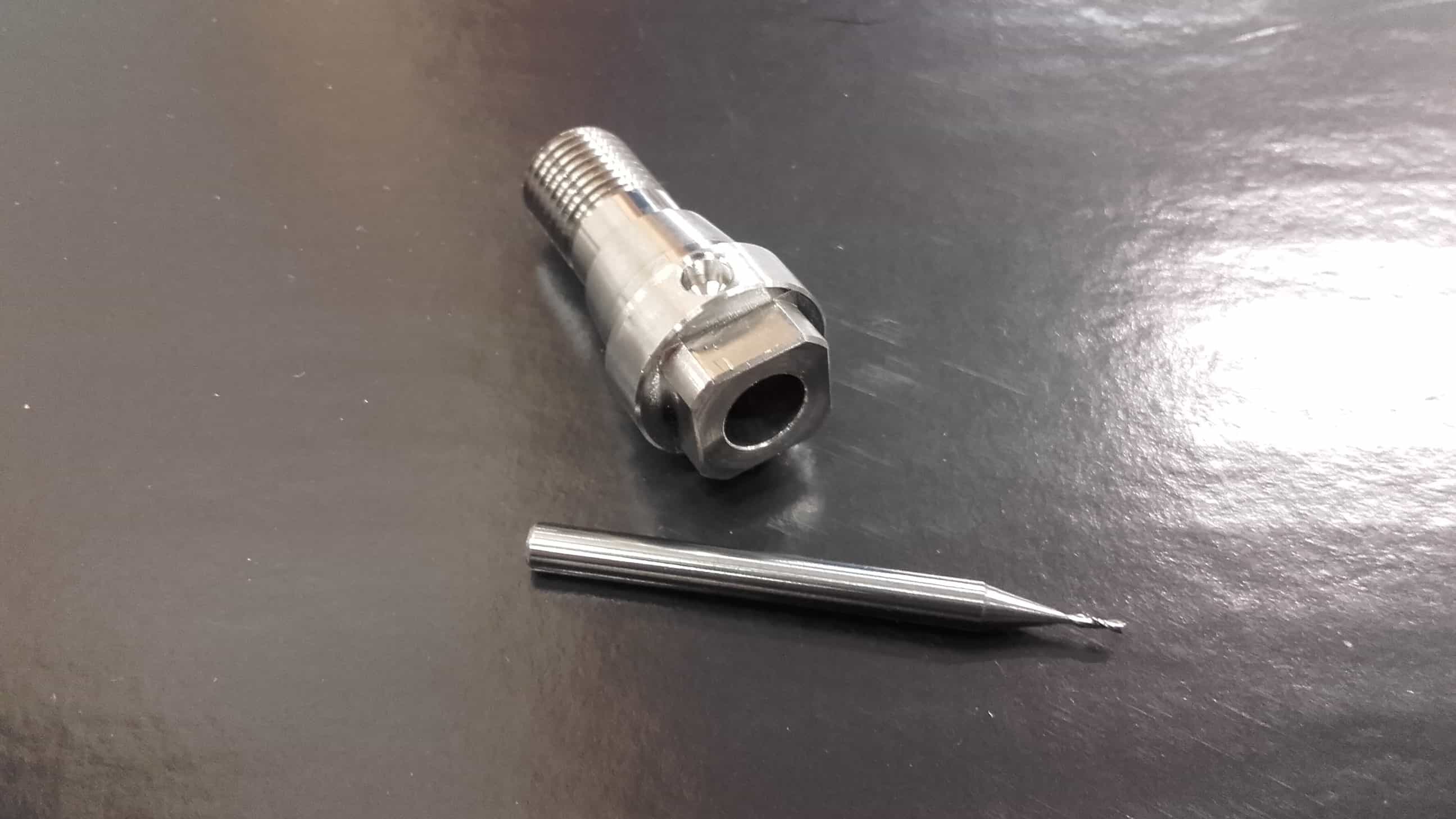
Almost There
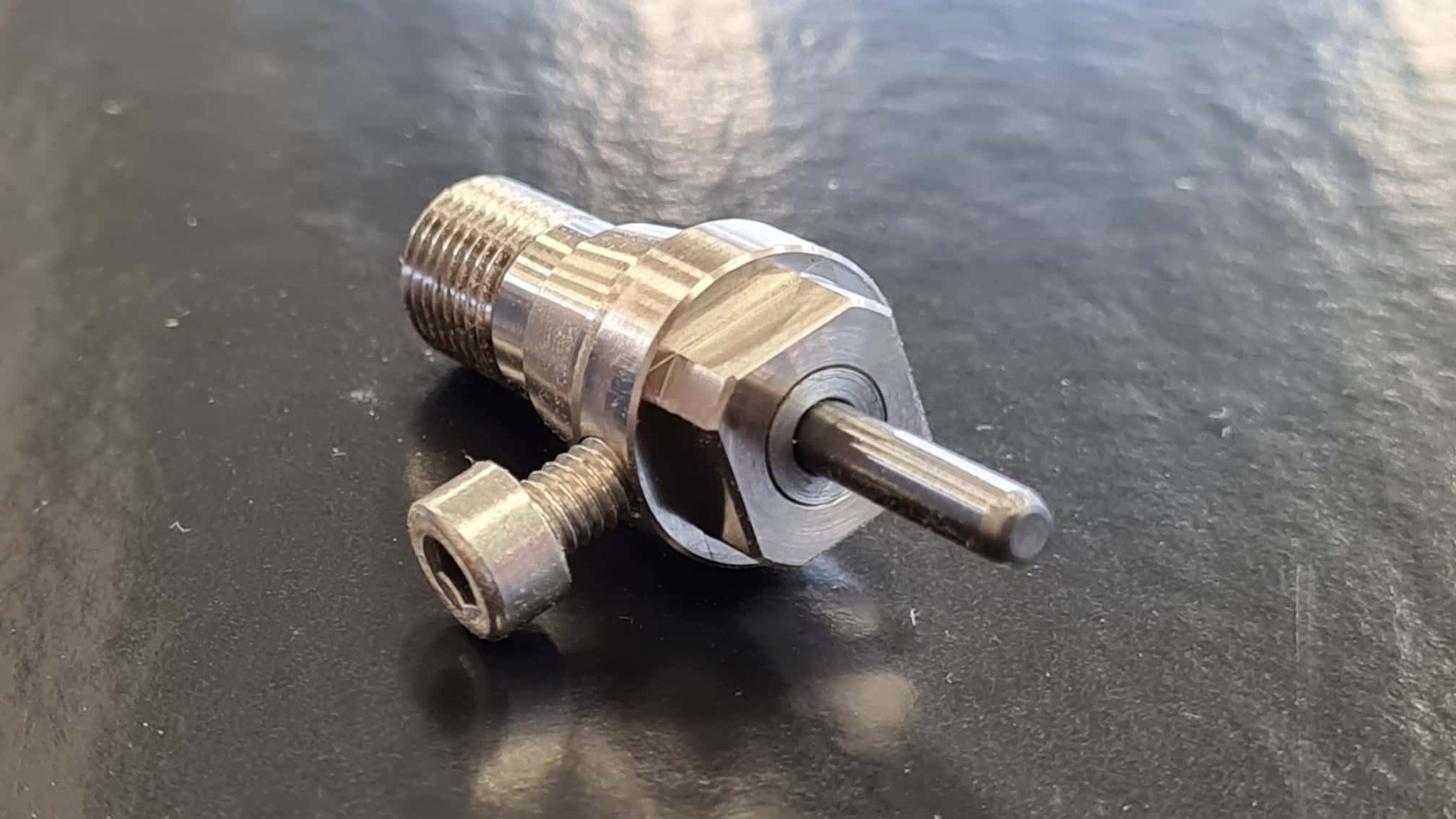
I cleaned it up with a file and a bit of sandpaper and then tested it out with an old broken tool and an M4 x 16 bolt since the shorter set screw would now need to be replaced. They all fit together nicely.
New Set Screw
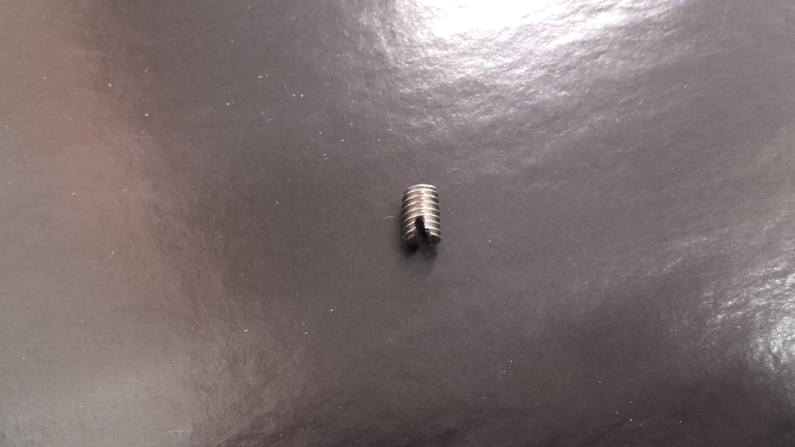
I was concerned about the head of the M4 bolt causing vibrations at the high rpm of the Roland, so I decided to remove the head and make it a set screw like the one it was replacing.
Success3

About 90 minutes after starting, I had finished the adapter. Amazingly, Marcello and Roland were also successfull in their back-up plans so now the lab has three different options in working order for CNC PCB cutting.
Milling PCBs
PNG to Gcode Workflow
PNG
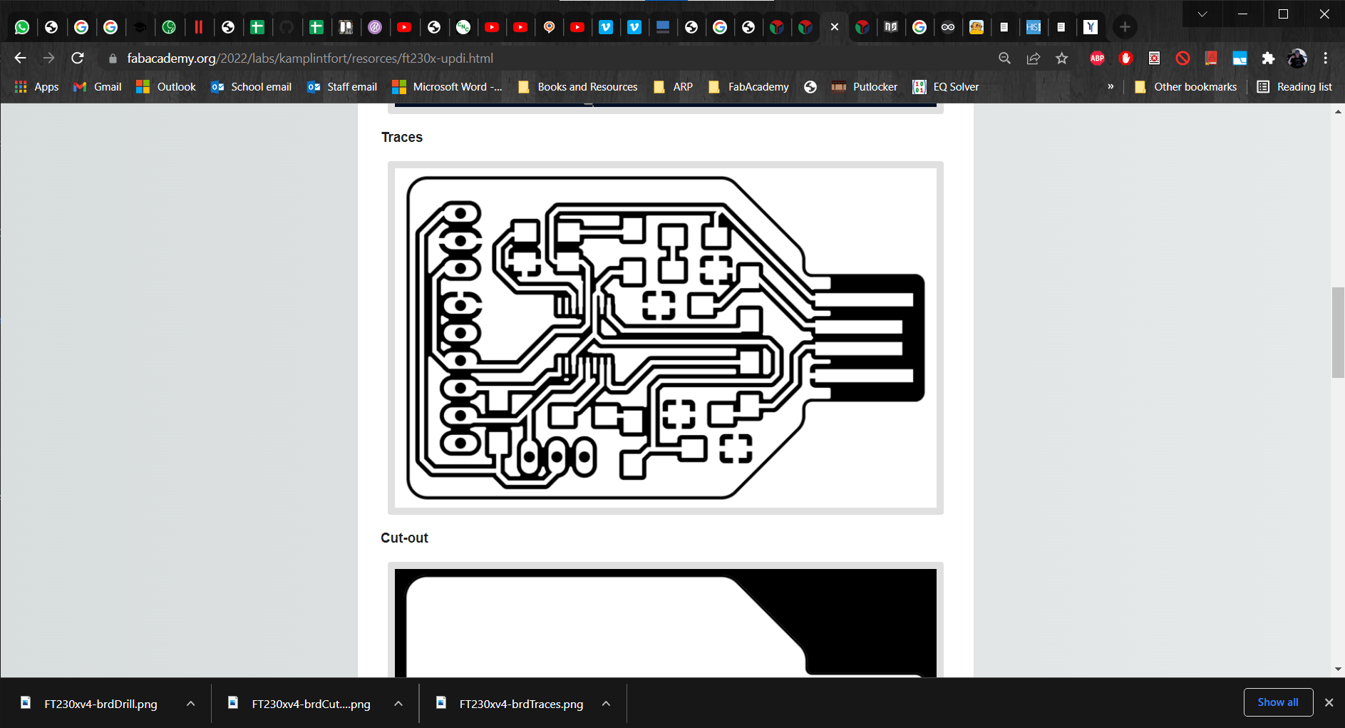
For my programmer, I decided to make the FT230x-UPDI that Ahmed made for FabAcademy so I began by downloading the PNGs.
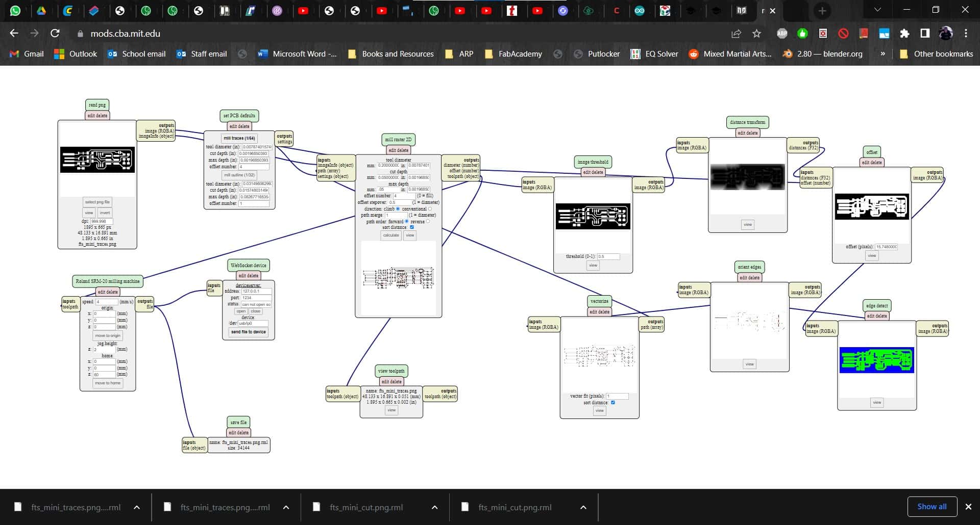
Mods
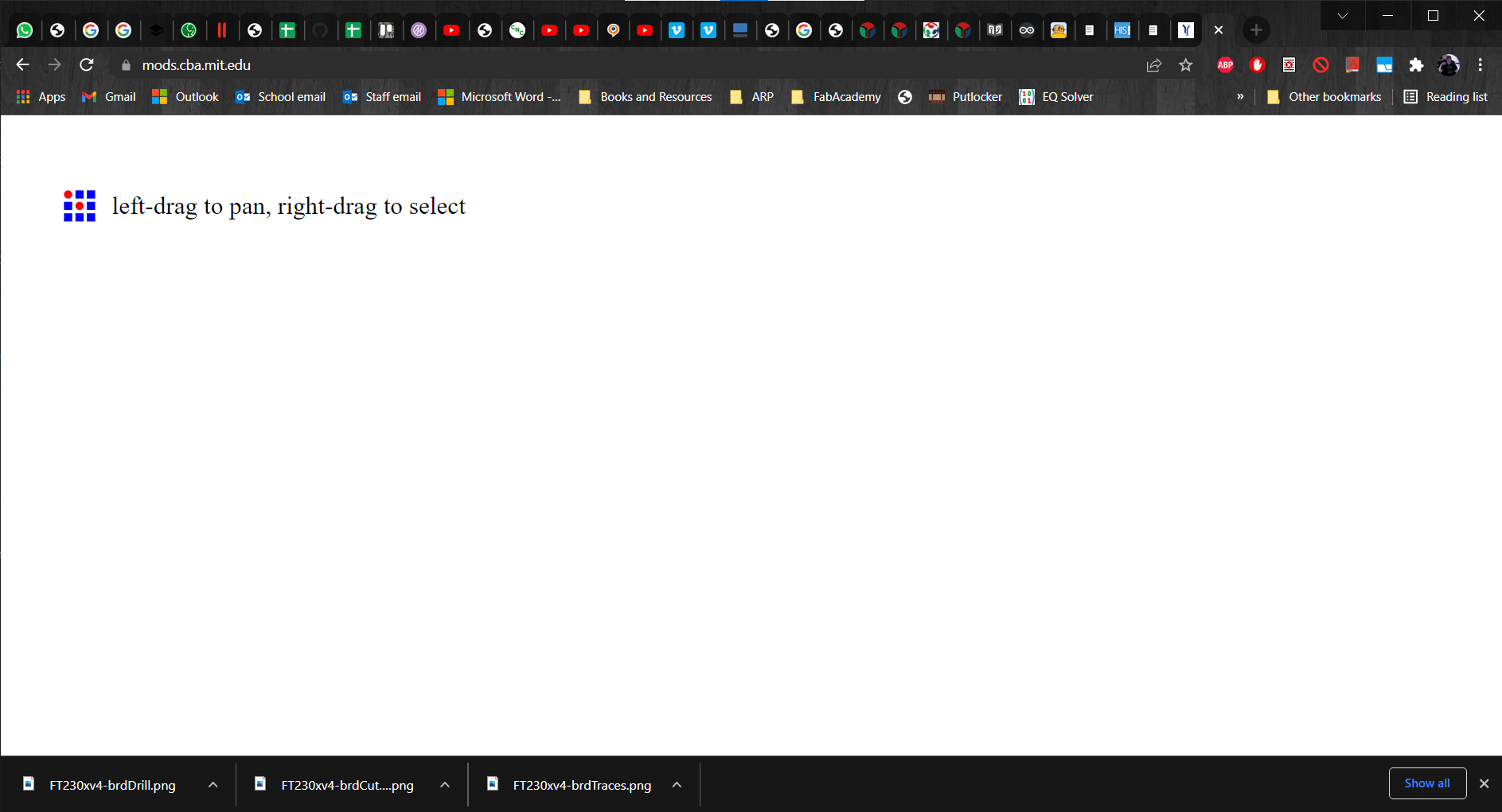
Then I opened up Mods to begin the conversion to gcode process.
Open Server Program
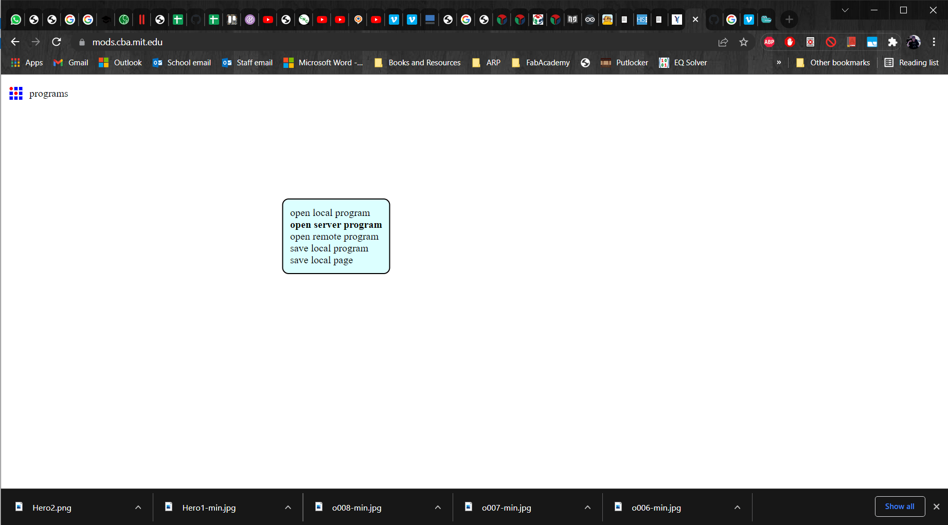
I right clicked to get to programs and then selected "open server program".
mill 2D PCB png
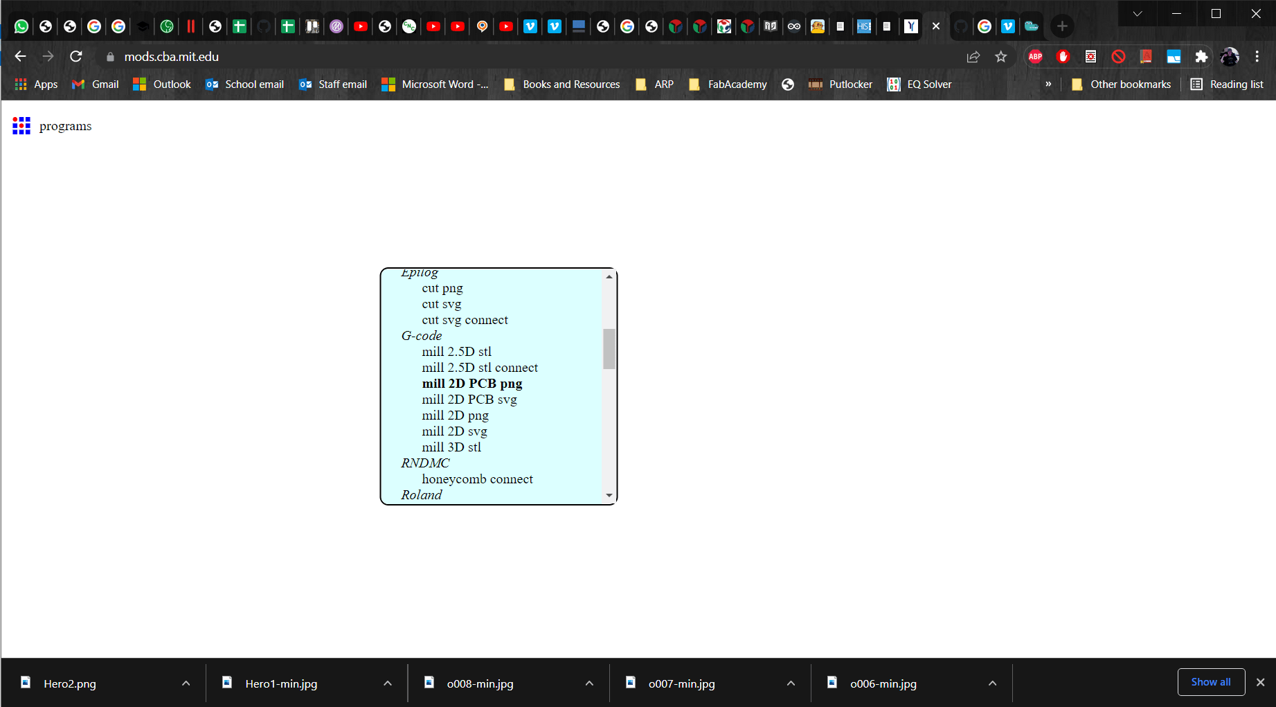
Then I scrolled down to G-code and selected mill 2D PCB png.
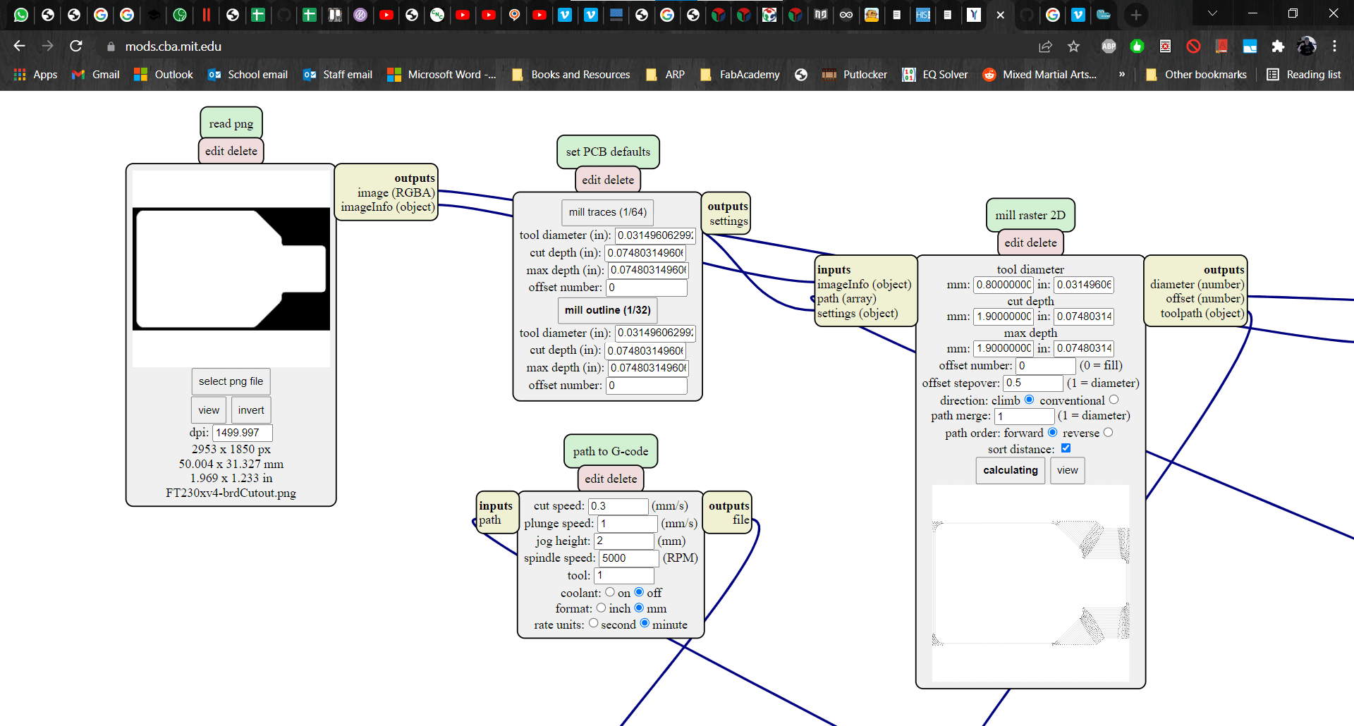
New Path
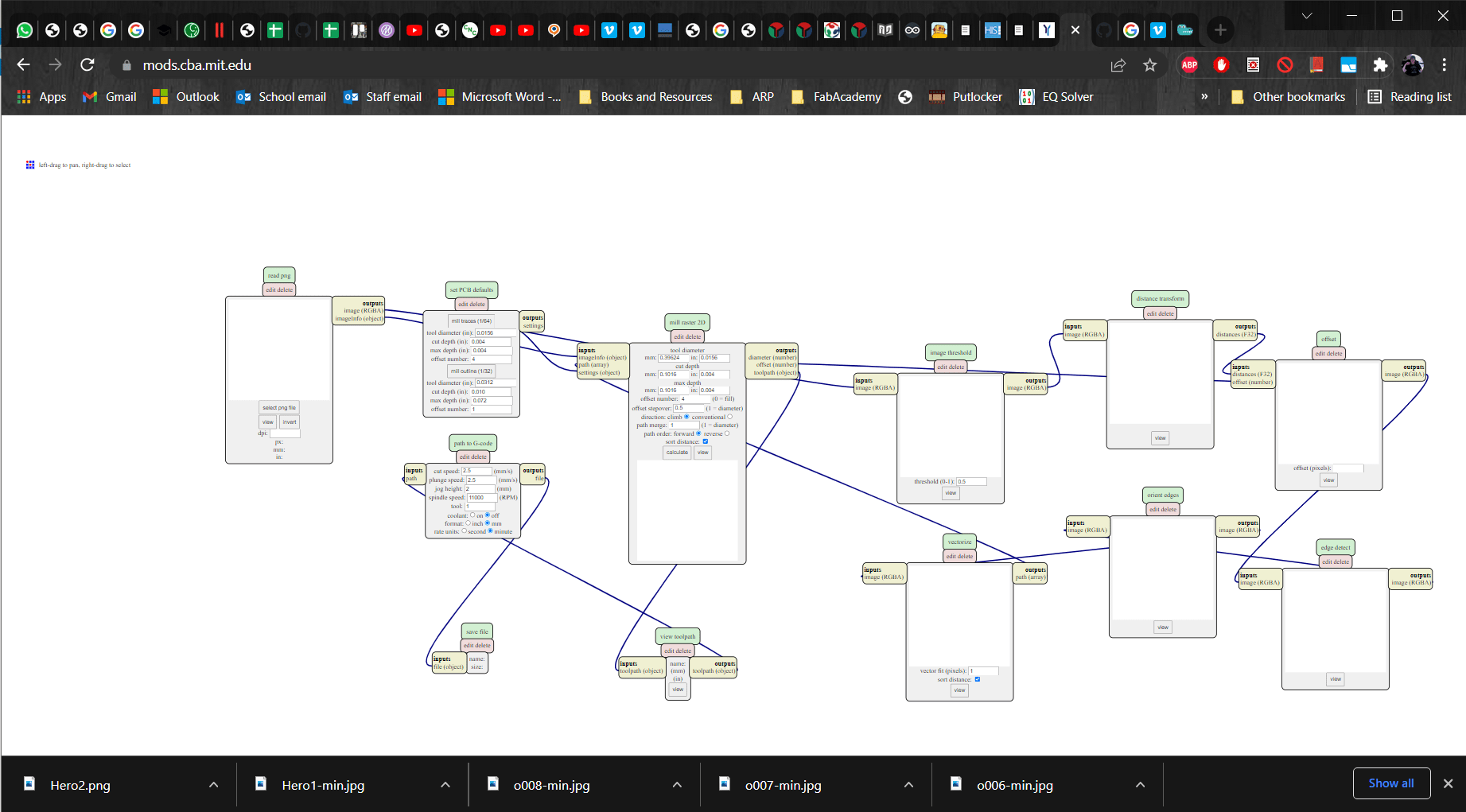
This brought up a png to gcode path that works with the Genmitsu. The save module is already included in this path so I did not have to add it.
Upload png
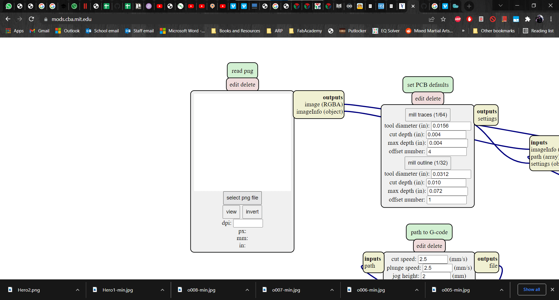
Then, in the "read png" module, I clicked on "select png file" and uploaded the png of the PCB I wanted to cut.
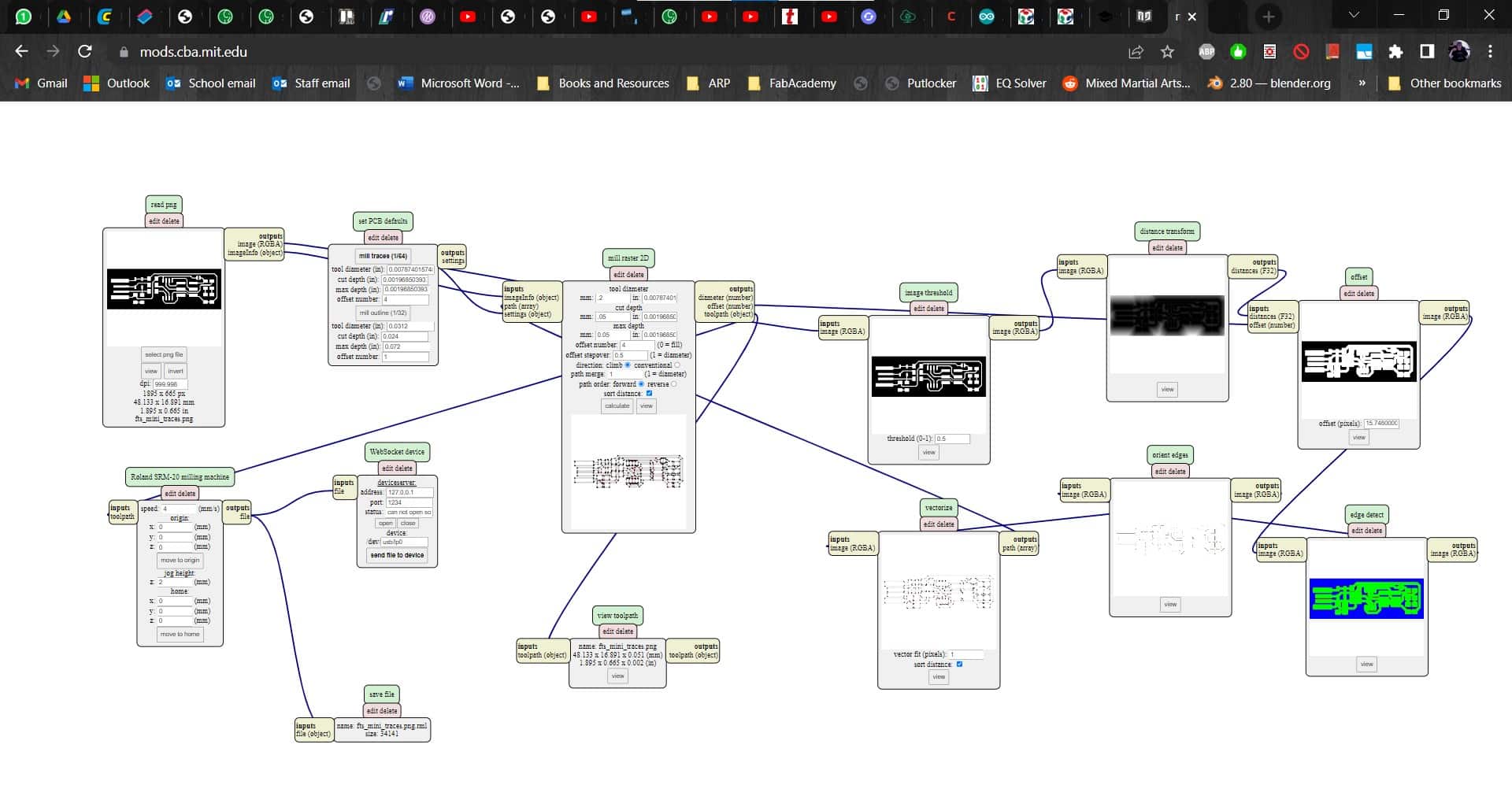
Parameters for Milling Traces
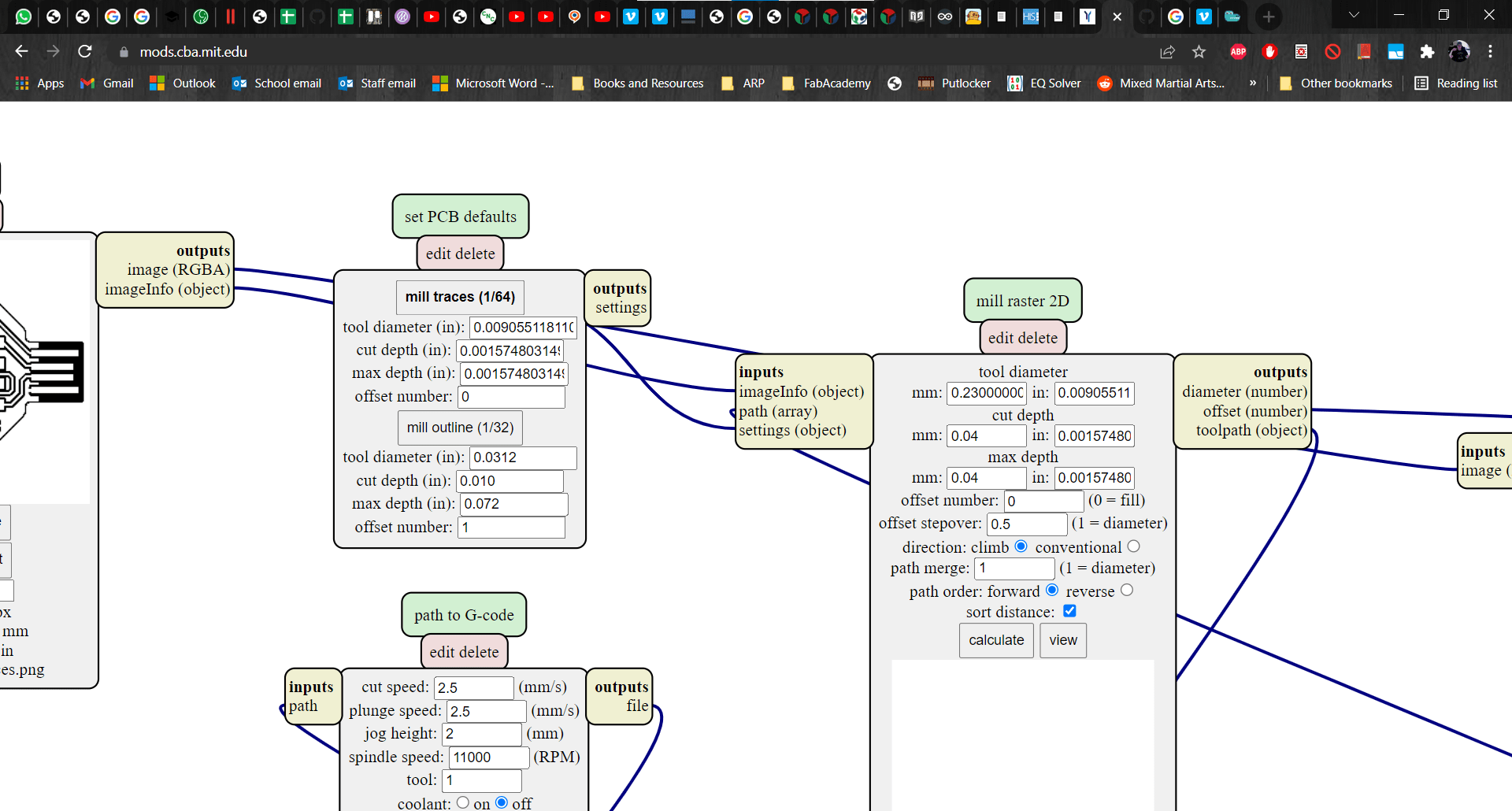
After clicking "mill traces (1/64)" in the "set PCB defaults" module, I moved over to the "mill raster 2D" module to enter the values for my parameters. I used a 0.23 mm micro-engraving tool and set the depth of cut and max depth for cutting the traces to 0.04 mm since the copper plating on the board is 0.35 mm thick. I decided to go with 0 for the offset number more as a test than anything else. I didn't quite understand what it meant so I just decided to try first with a full fill. I kept the rest of the defaults in the module and I copied the inch values over to the appropriate fields in the "set PCB defaults" module.
path to G-code
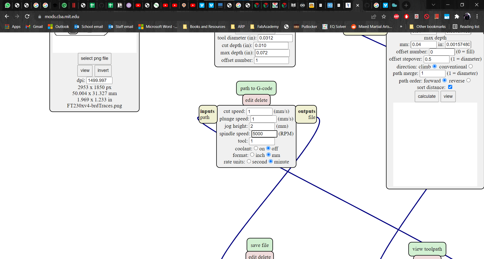
Next in the "path to G-code" module, I changed the cut- and plunge speeds to 1. The only other parameter that I changed here was the spindle speed. I went with 5000 RPM because I am used to conventional machining and that already sounded crazy high to me. I would learn later that, for PCB cutting, spindle speeds over 10k RPM are the norm. I left the rest of the paramters in this module at their default values.
Calculate
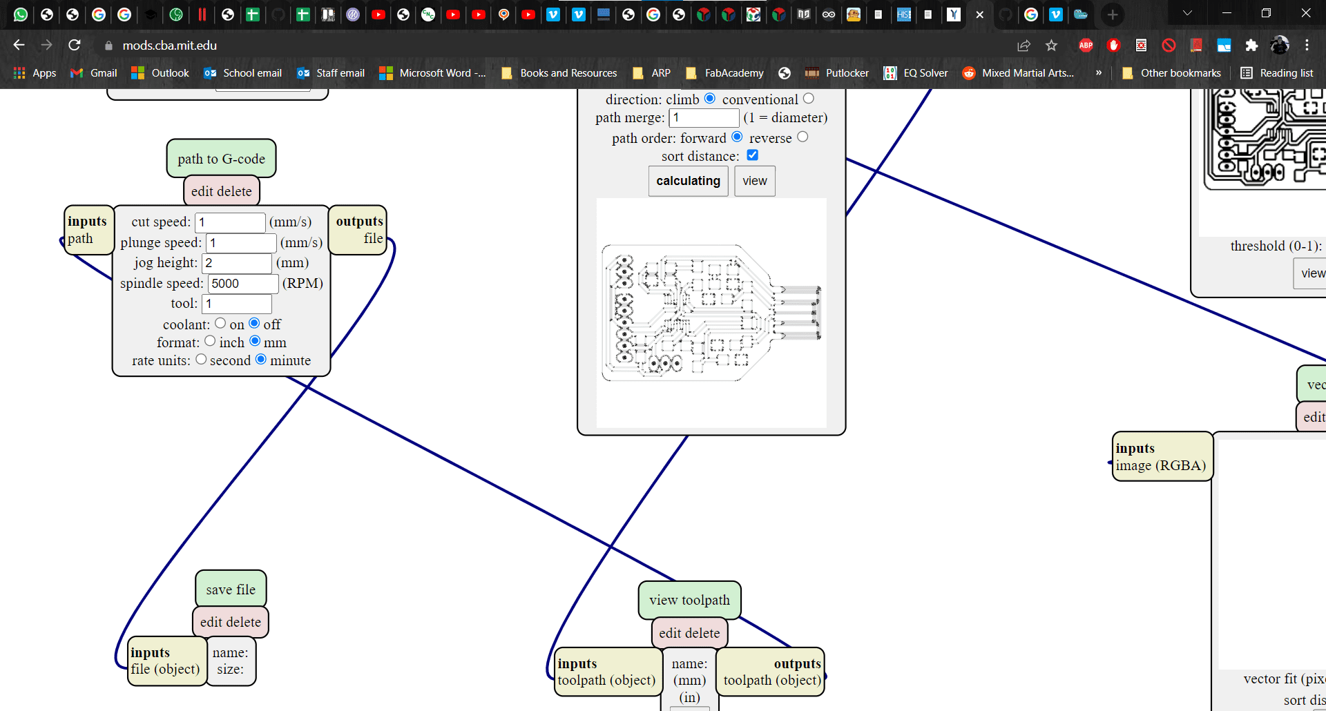
Finally, back in the "mill raster 2D" module, I clicked calculate.
Save G-code
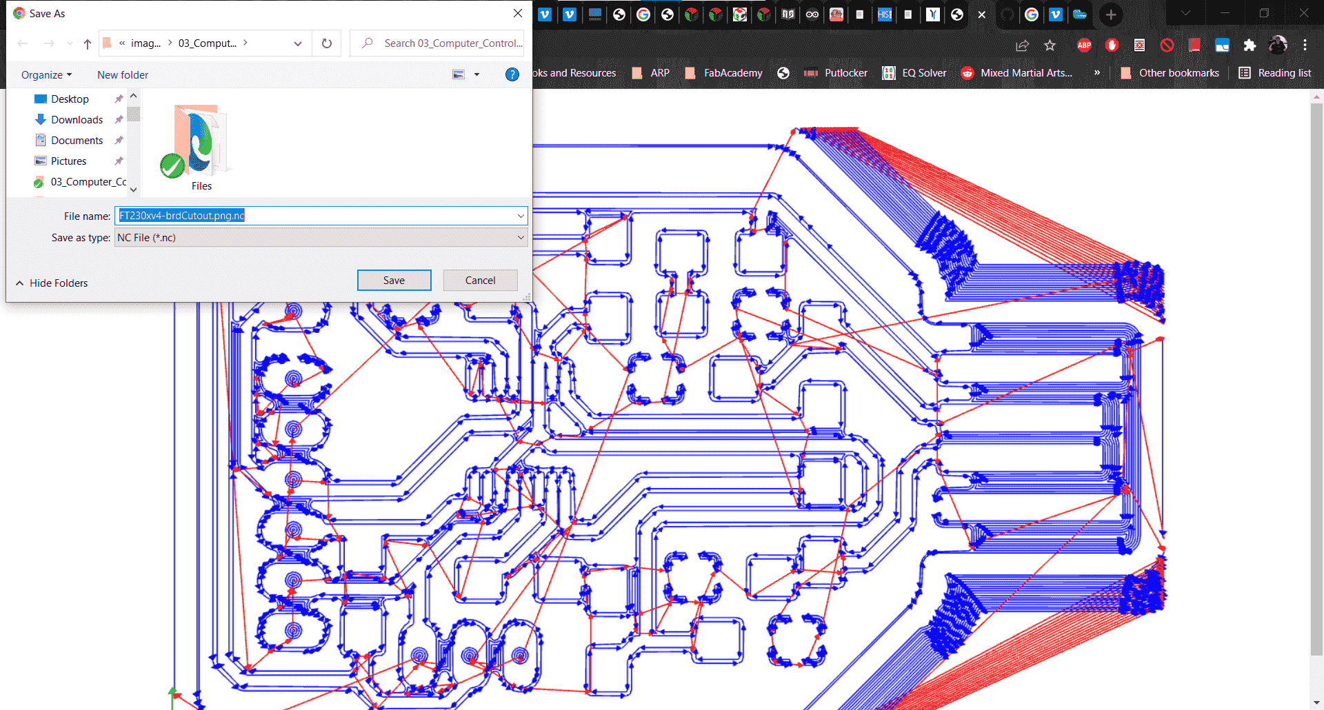
This brought up a new window showing the CAM as well as a dialogue box where I could save the new g-code as a .nc file.
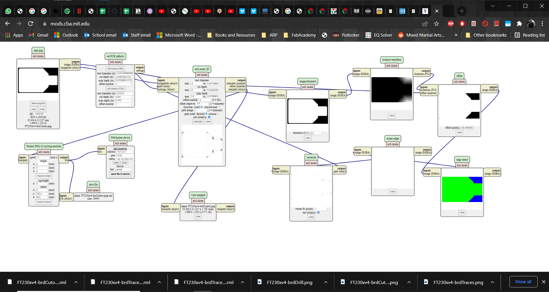
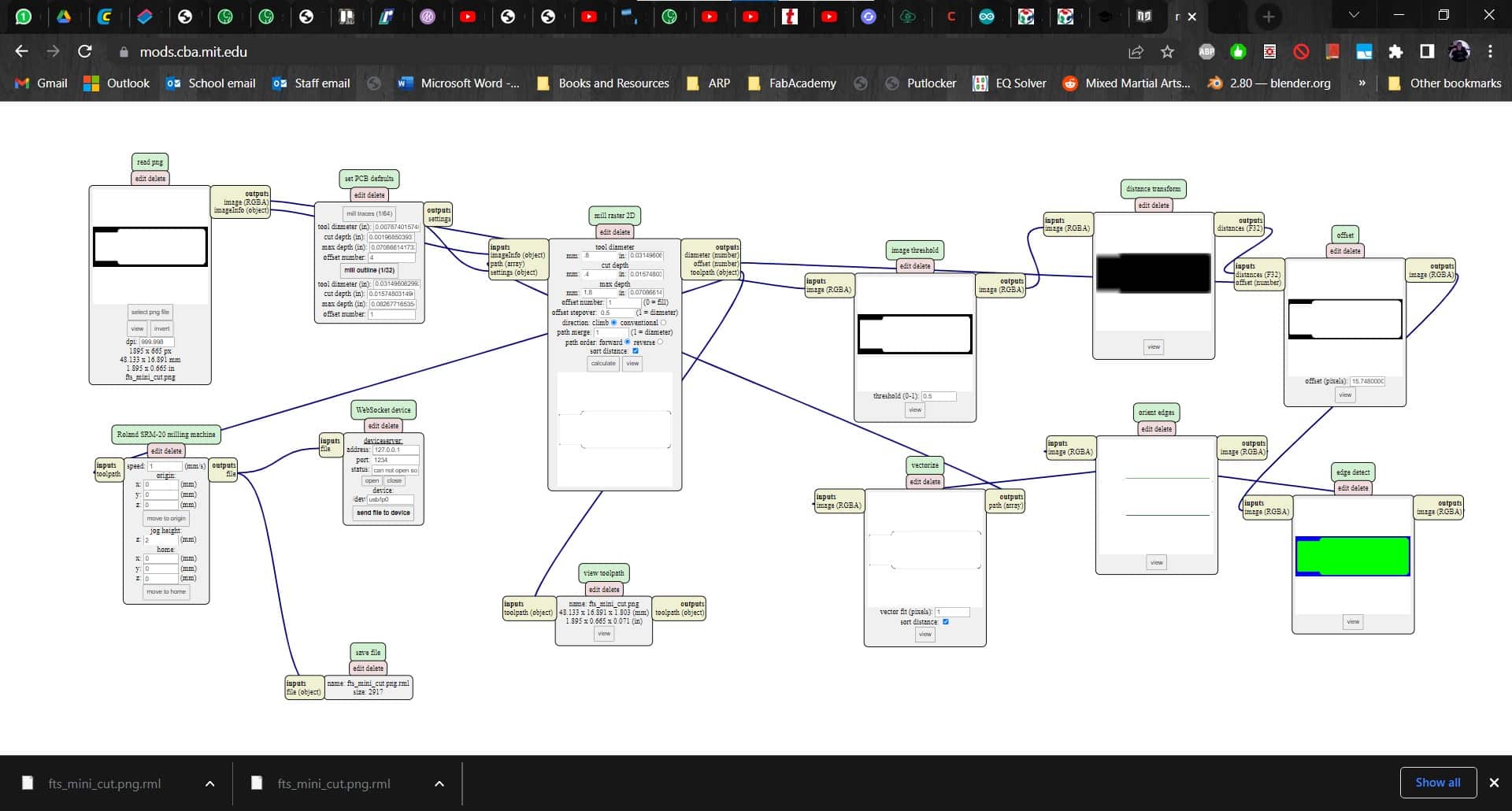
Repeat for Cut-Out
I repeated the process, but this time changed the parameters for milling the outline. I used a 0.8 mm endmill and set the cut depth and the max depth to 1.9 mm to ensure that I would cut through the whole board in a single pass. I changed the offset number to 0 and changed the cut speed to 0.3 since I was now cutting very deep relative to cutting the traces. Calculate. Save. And now I was armed with my g-code files and was ready for some PCB cutting action.
Practicing for the Roland
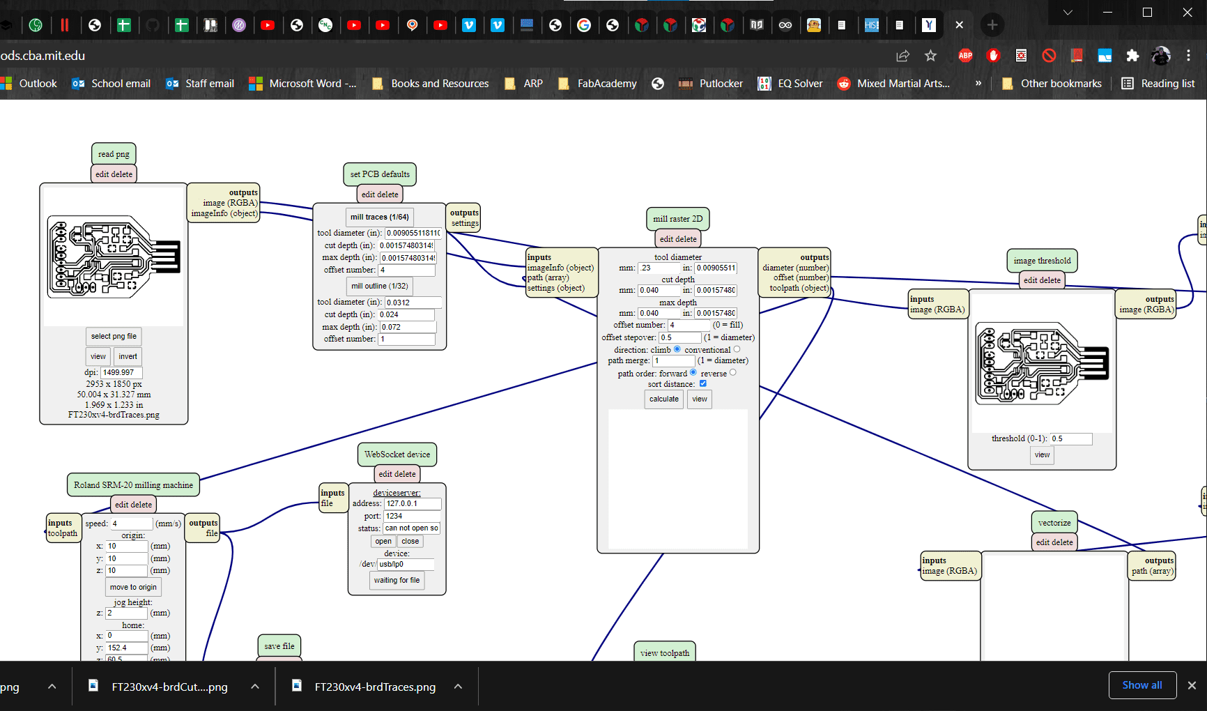
It wasn't quite my turn on the Genmitsu yet, so I decided to use MODS to generate another set of g-code files in case I ever want to cut this programmer using the Roland instead of the Genmitsu. I kept the parameters the same, but this time changed the offset number to 4.
Cut-Out Too
For the cut-out, I decided to change things up a bit. This time I went with a more conservative 0.6 mm depth of cut (so the cut-out would take 3 passes), but I left the cutting speed at 1. Technically this should take about the same amount of time, so I am curious about the difference in quality, if there is any.
Milling
Changing Port
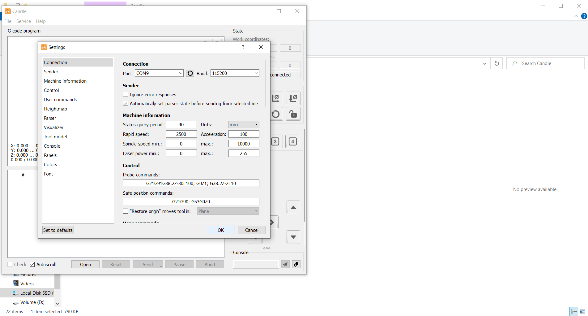
After installing and opening Candle, I connected to the Genmitsu via USB and then selected the appropriate port in settings.
Upload G-code
I used the jog buttons to set my zeros and then uploaded my g-code.
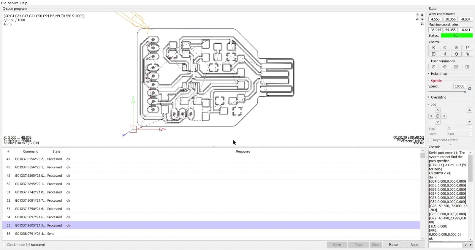
Cutting
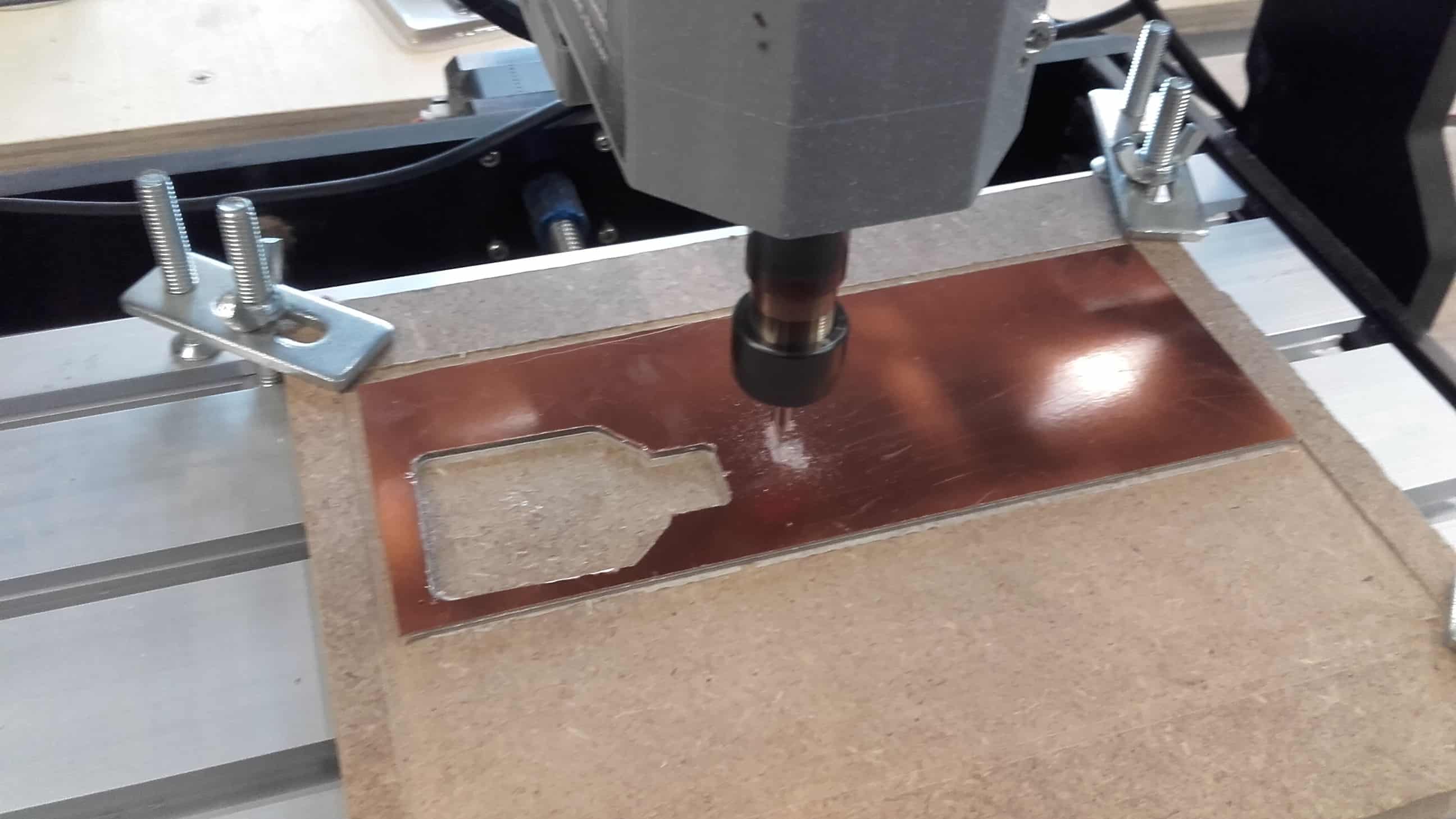
I hit send and watched the magic begin.
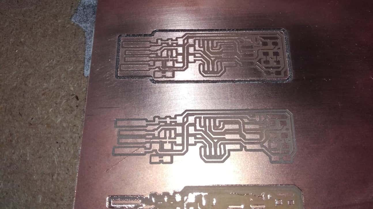
So Far, So Good
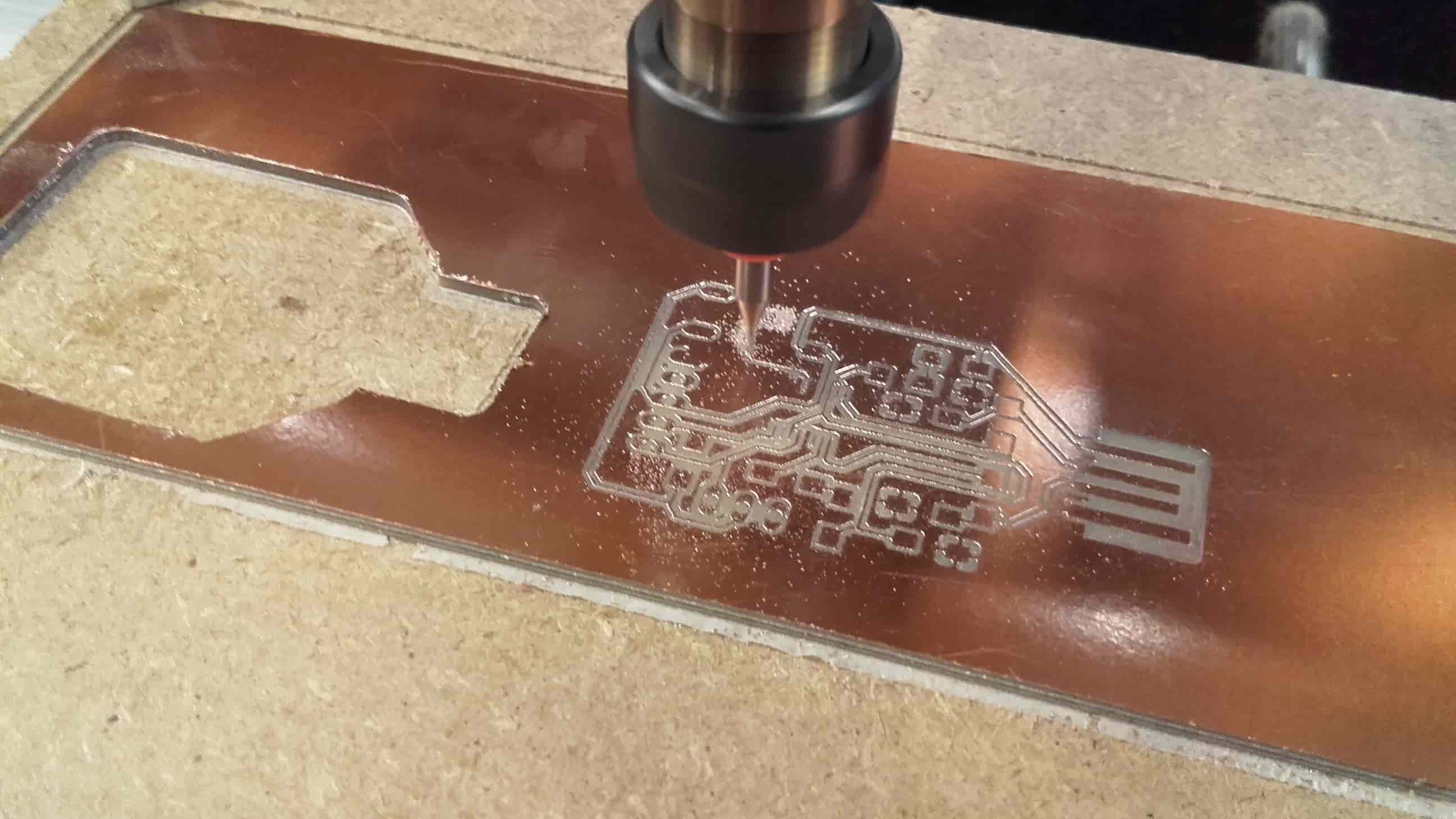
Everything seemed to be cutting beautifully...
Ruh Roh
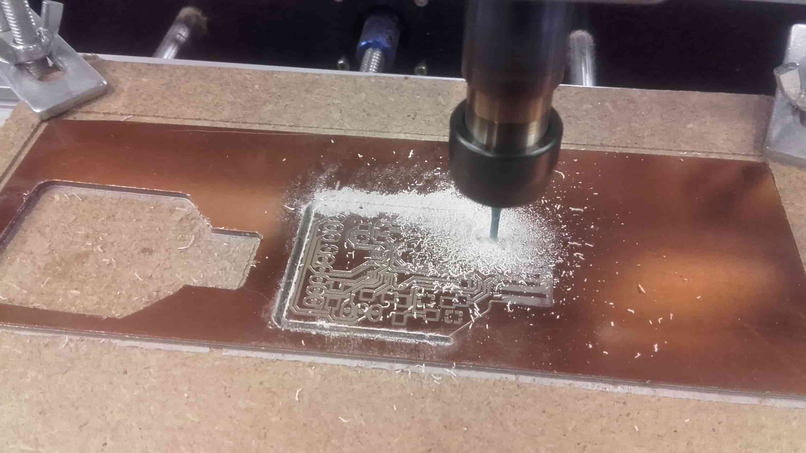
...until I was cutting the outline and noticed a minor flaw.
Not Cutting All the Way Through
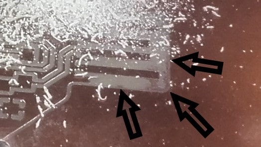
On one corner of the board, near the USB connection, the copper layer wasn't completely removed. This was a surprise since I had chosen 0.04 mm for the cutting depth (presumable more than enough to cut through the 0.35 mm copper layer), but I guess the double sided tape must have been a little thinner in that area. I was able to clean this up pretty easily with an exacto knife after the cutting was finished so it was no big deal in the end.
Cleanup
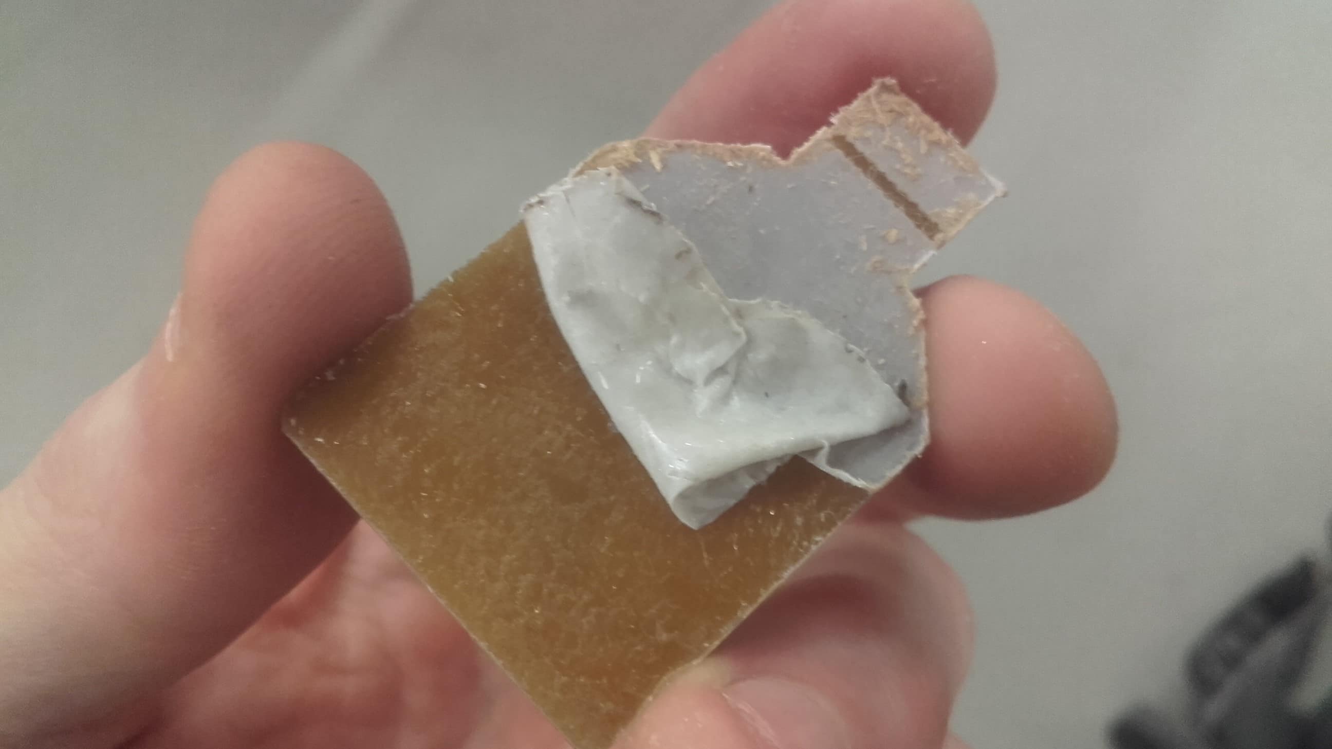
I removed the double-sided tape and cleaned the board with acetone. I also used a steel ruler as suggested by Niel to remove the tiny burrs, but I kind of wish I hadn't. It removed the burrs, but it left some marks on the board that aren't aesthetically pleasing.
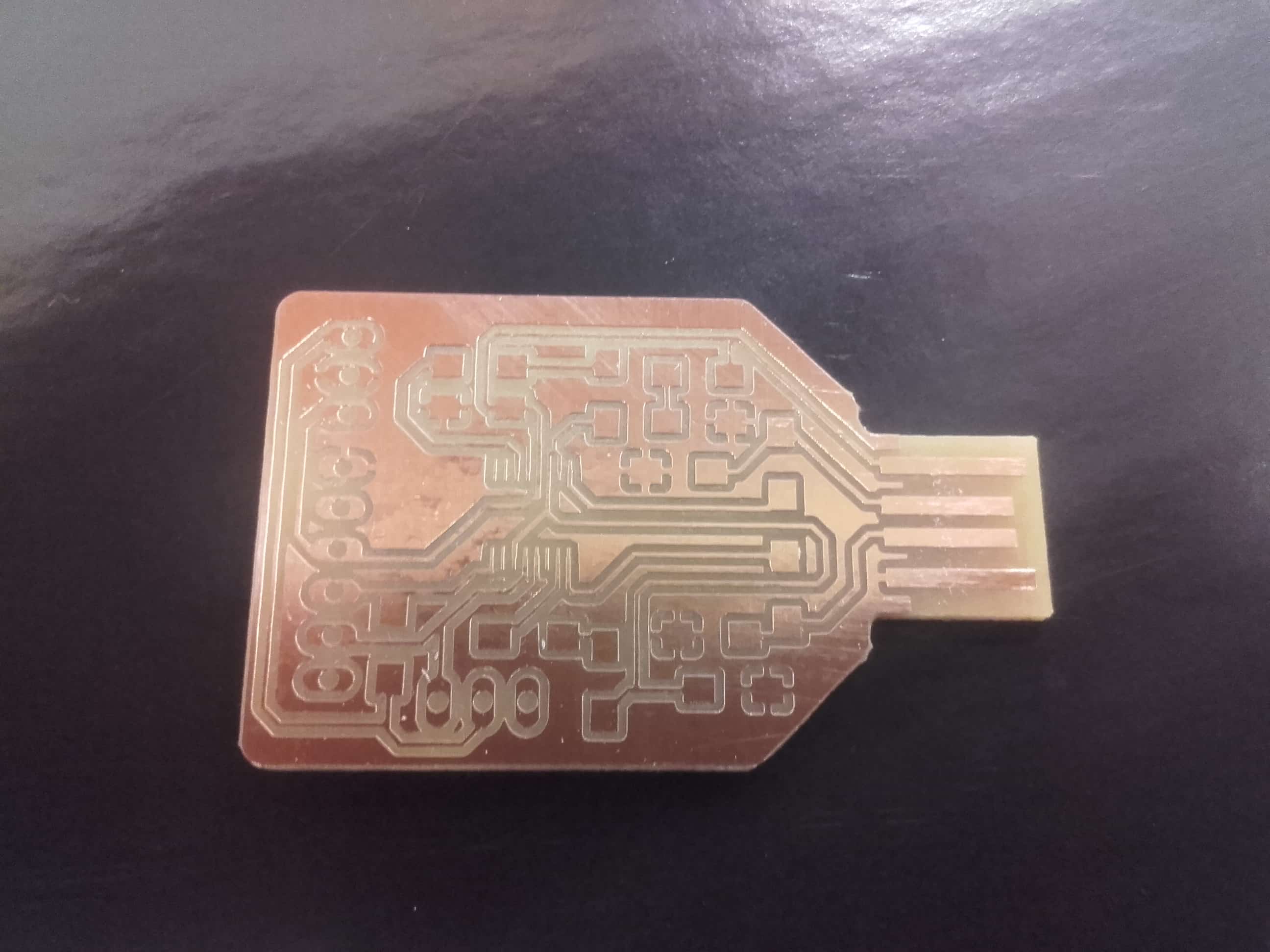
Victory!
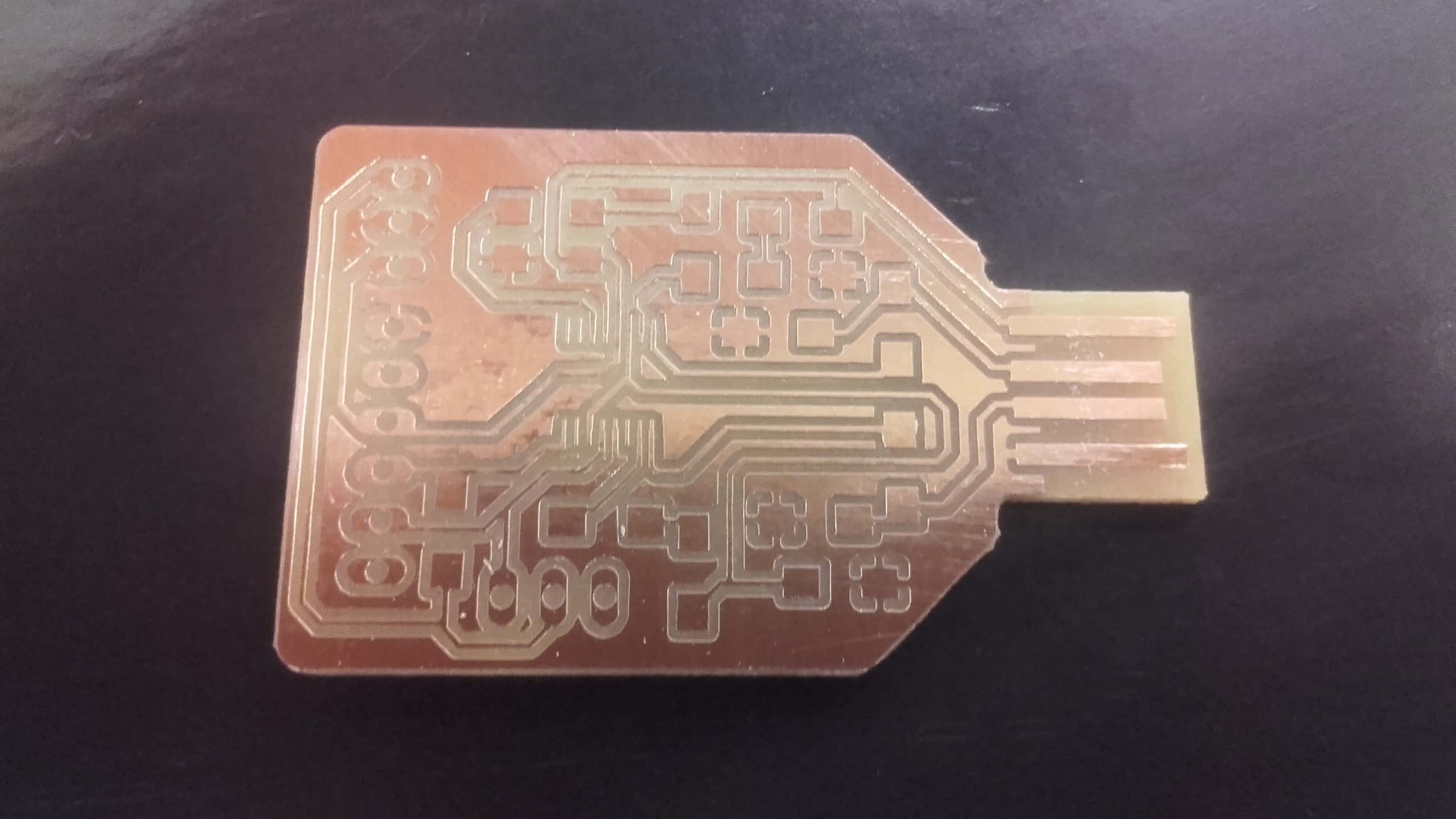
I was told that those marks can be removed easily using steel wool so I will get some and give that a shot. Overall, I think the PCB looks great! The traces and gaps all look to be adequately sized for current to flow where it is meant to. I won't know for sure until we get our components from Kamp Lintfort and get them soldered to the board, but for now, I am pleased.
Adding Components and Testing
Populating the Board
Drilling
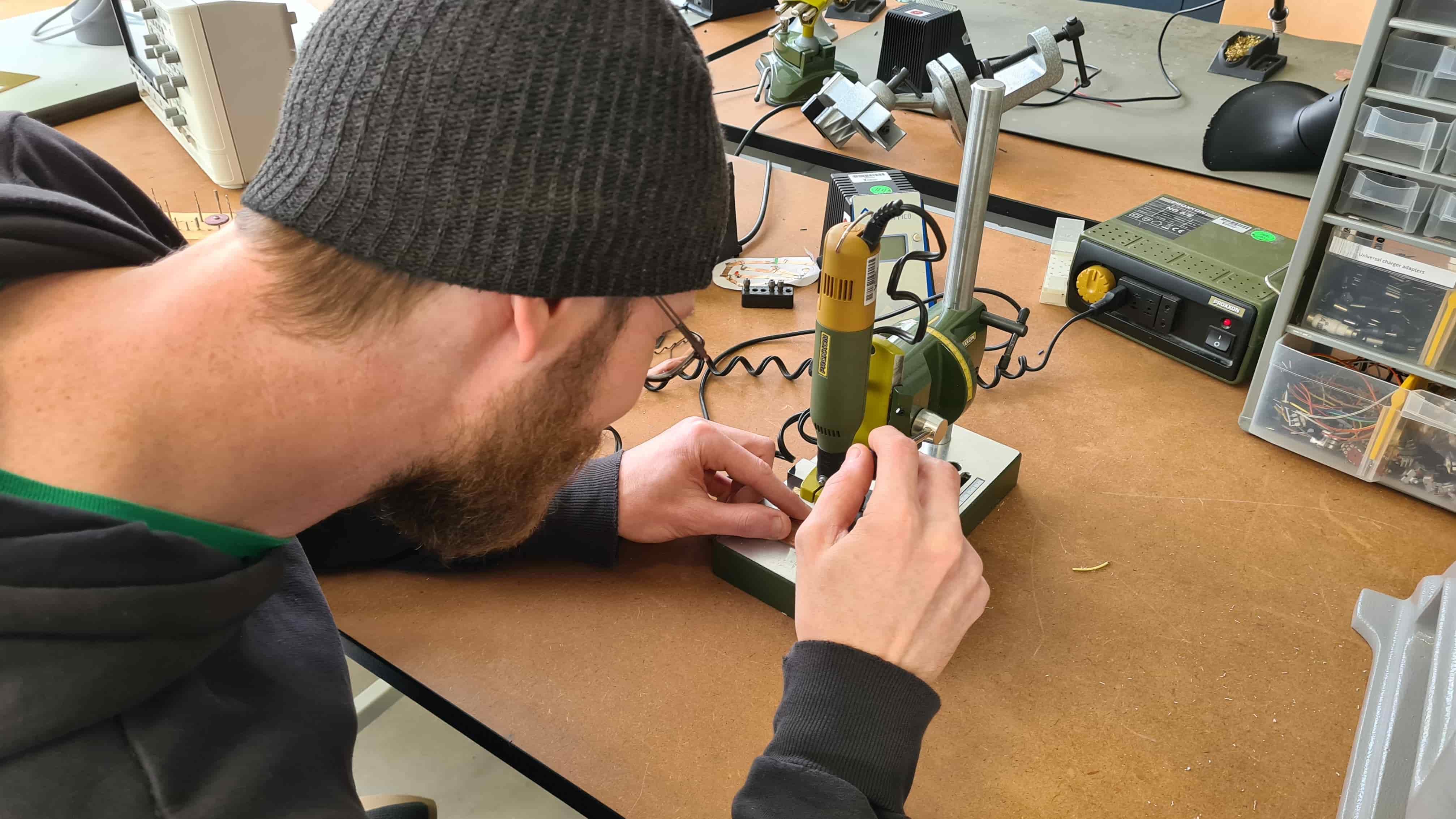
I started by drilling the holes that would be necessary for adding the components to the PCB I made.
Cute!
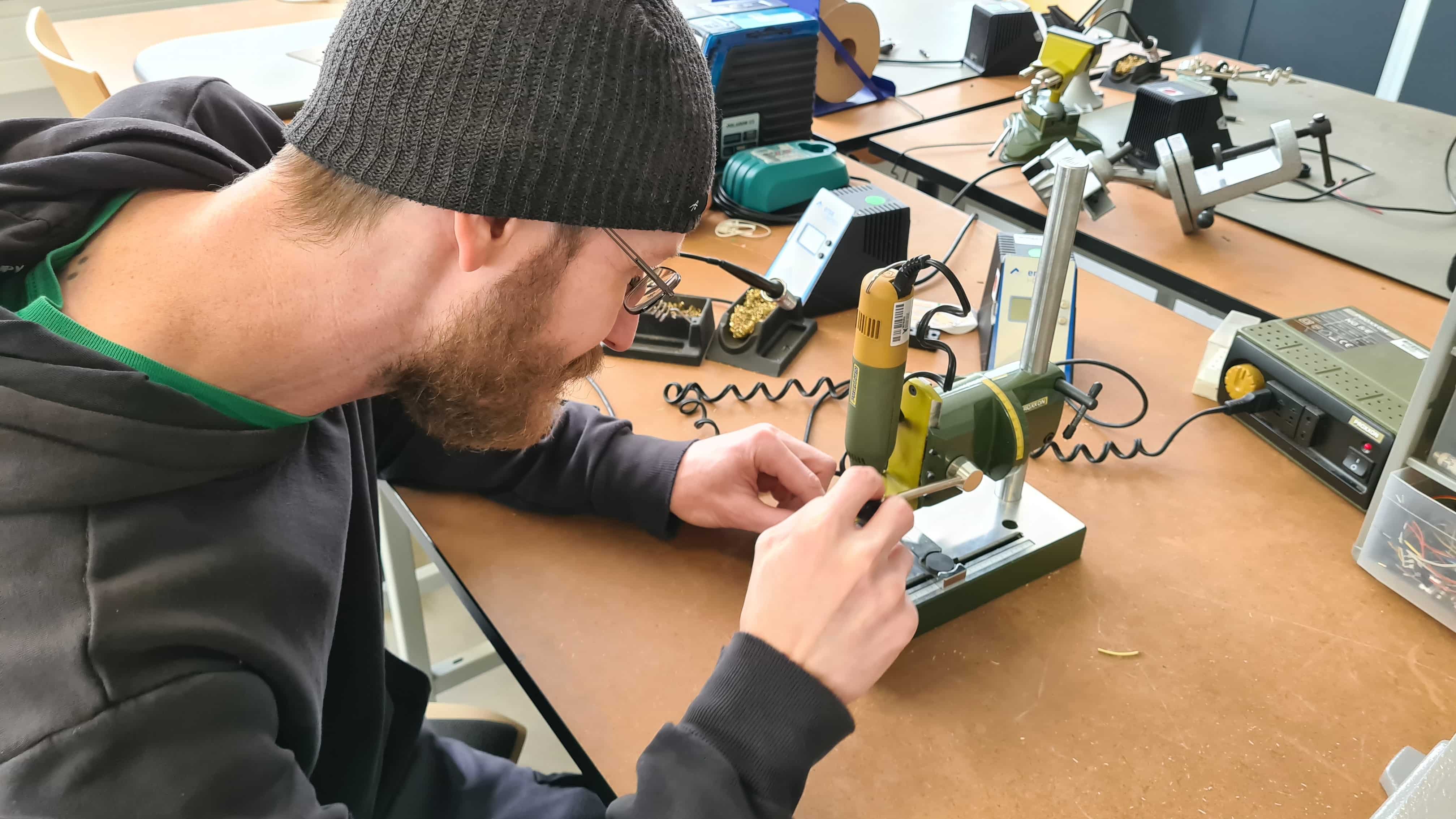
I really like this little Dremel drillpress so I decided I will make one someday. 😁
Components
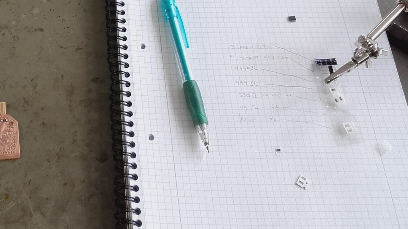
I was given my FT230xs chip and I collected the rest of the components I would need from the electronics cabinet in the Kamp Lintfort lab where I was working that day. Ahmed gave me a good tip about using tape to stick all the tiny components to my BoM list.
Starting Easy
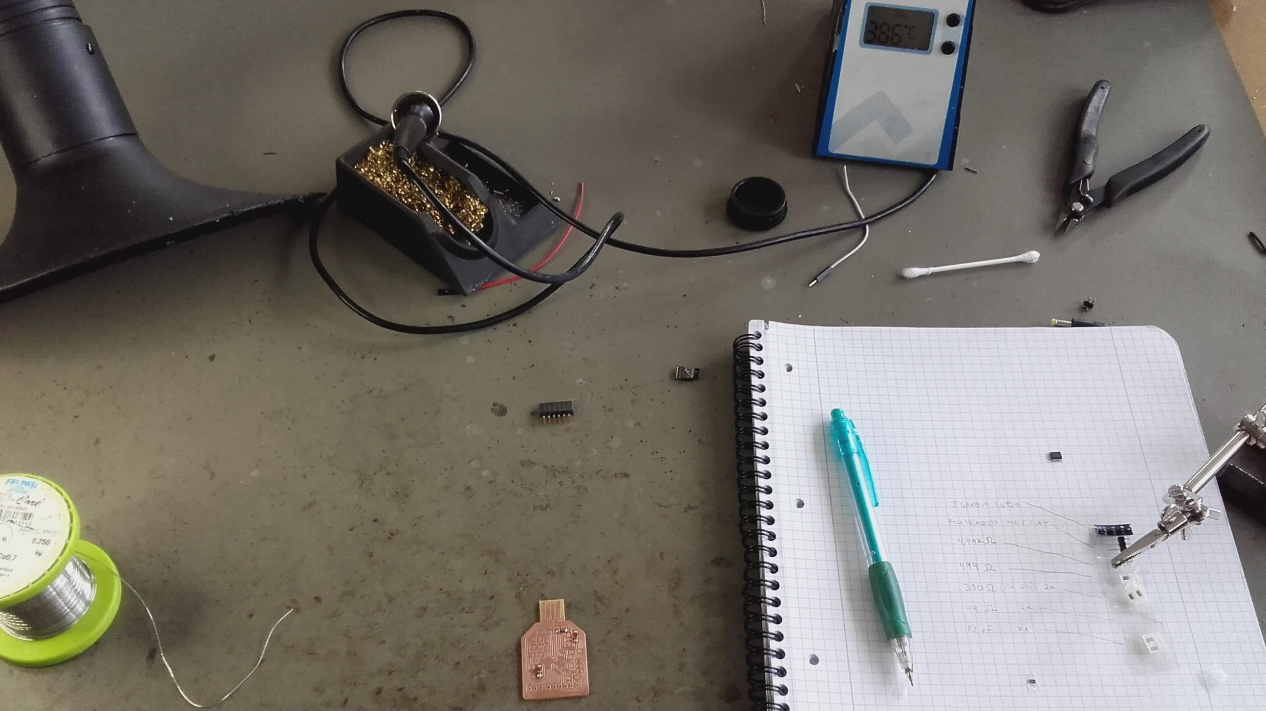
The processor chip is tiny, so I decided to start with a few larger components for my first ever soldered connections (technically not true...I once fixed a TV remote and a game controller using lead based solder...and a woodburner lol). I started with a few capacitors to get a feel for the process.
Processor
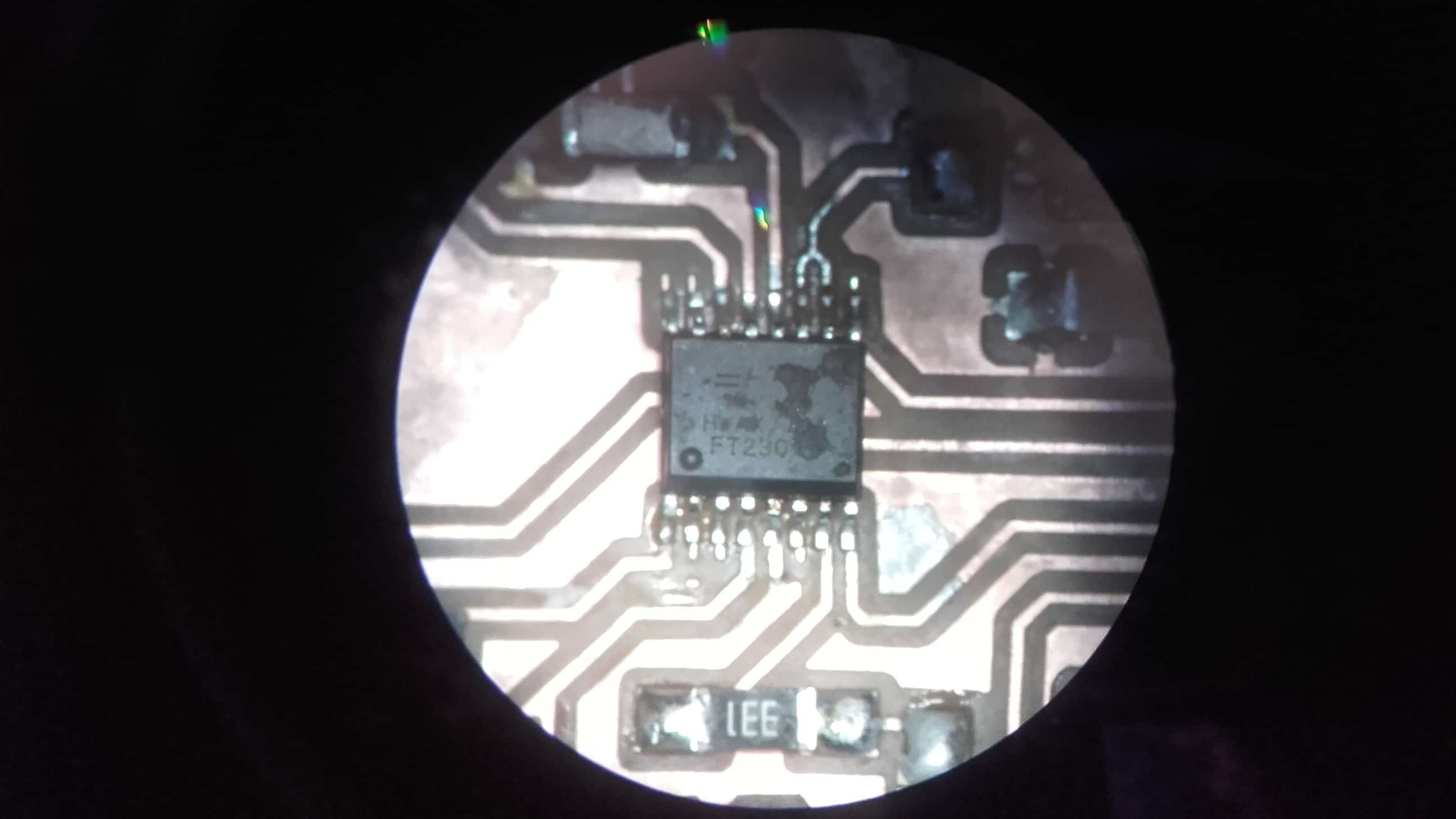
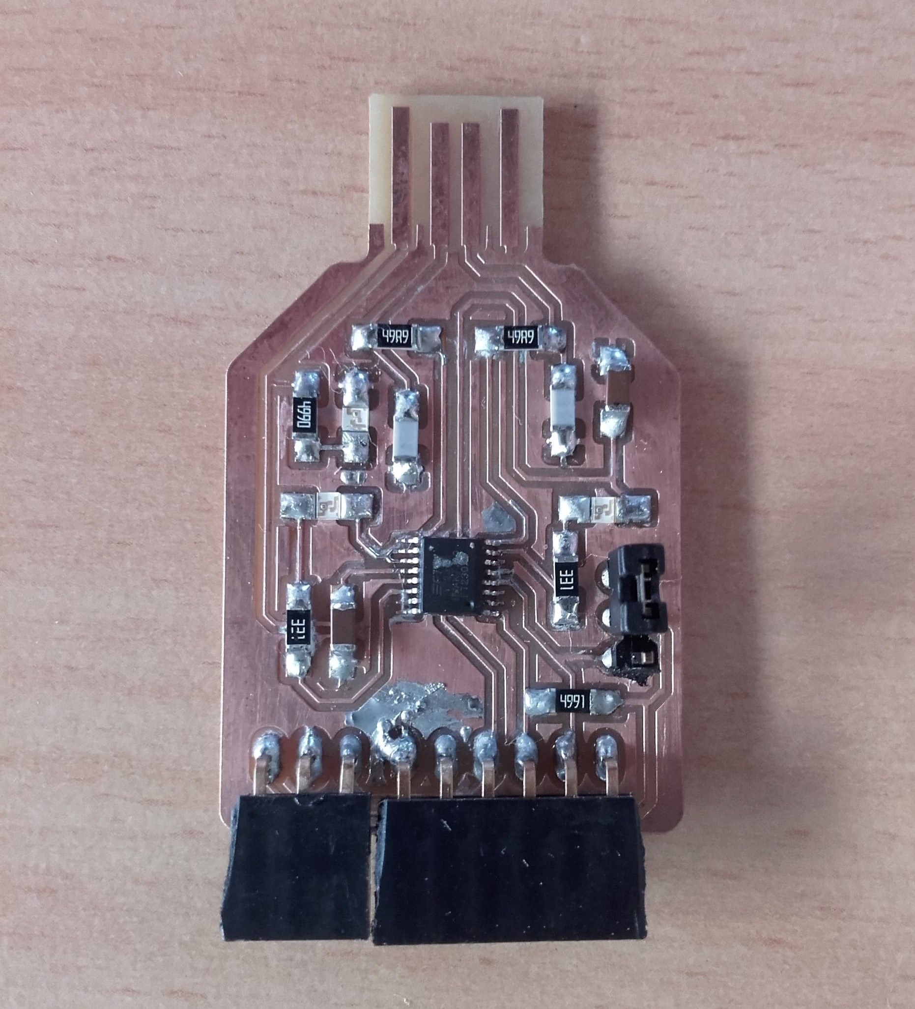
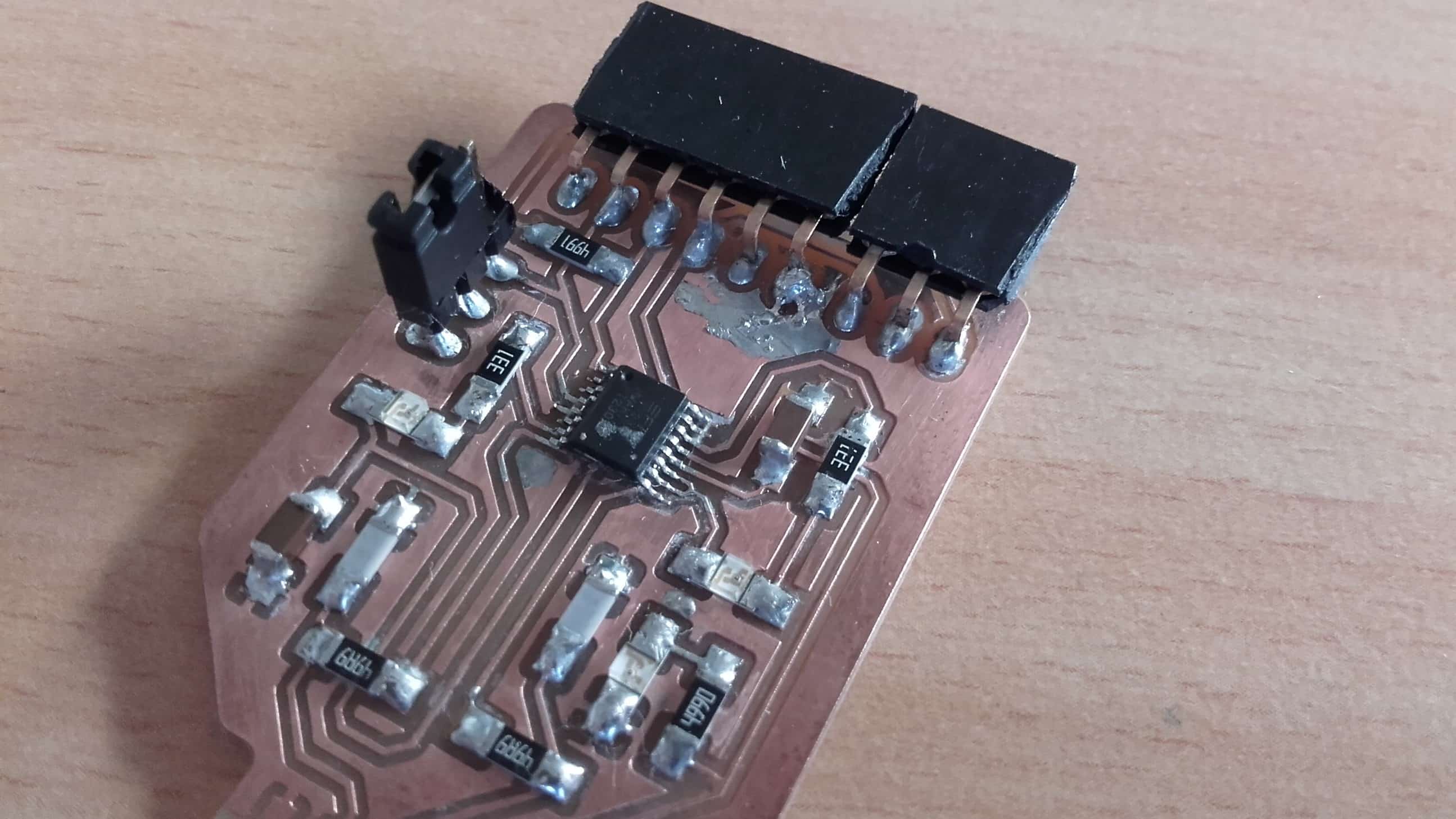
Once I felt ready, I added the chip to the board. I heated up all the pins and overflowed solder across all of them. Then I used a wick to soak up the excess. It took a few tries to get everything stuck and to end the process with the wick unsoldered to the board, but overall I think it went smoothly. Here is a pic of the soldered joint in the microscope.
Doublechecking
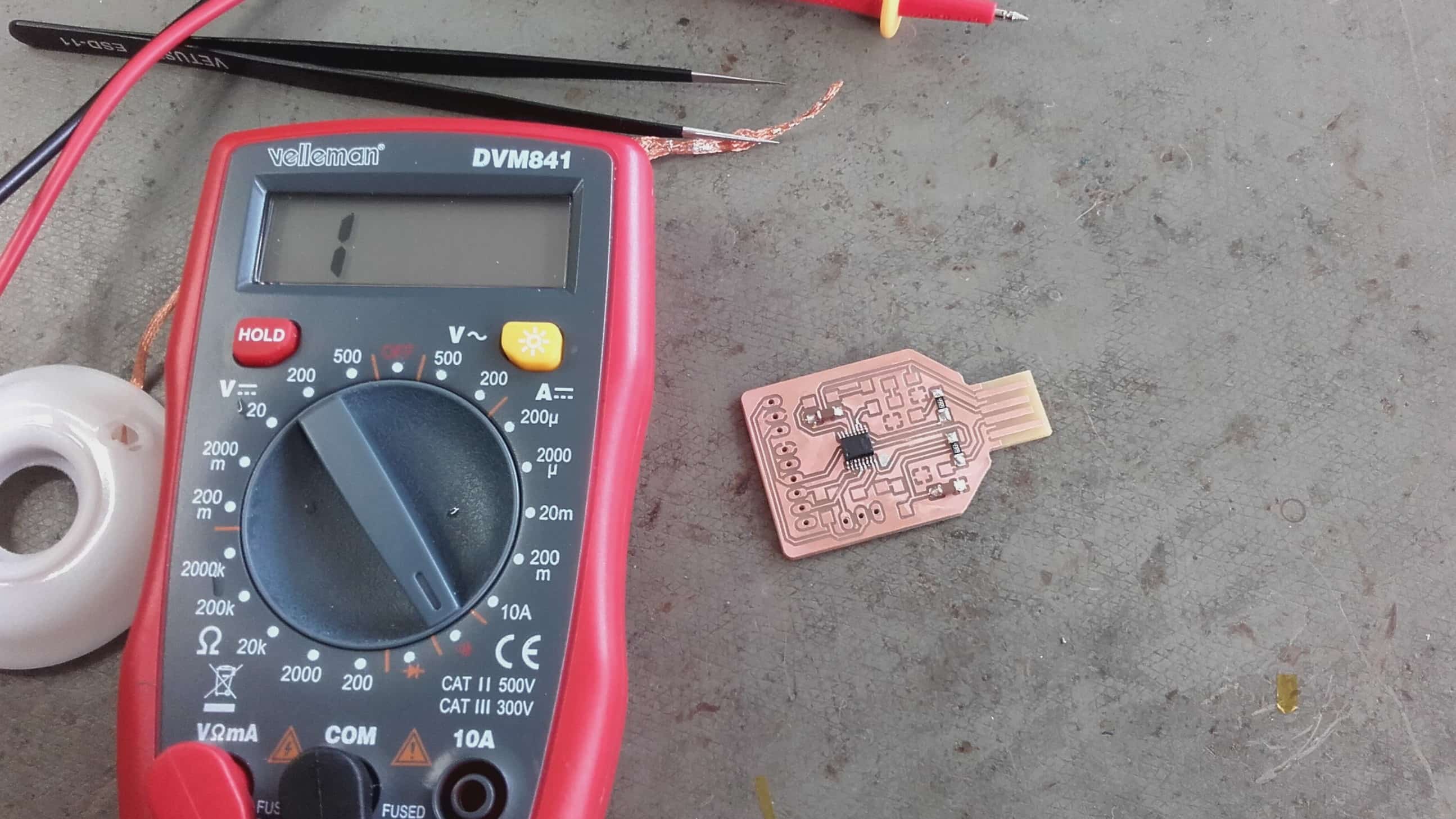
Then I tested for continuity where it should be, and lack of it where it shouldn't be. Success!
Finishing the Job
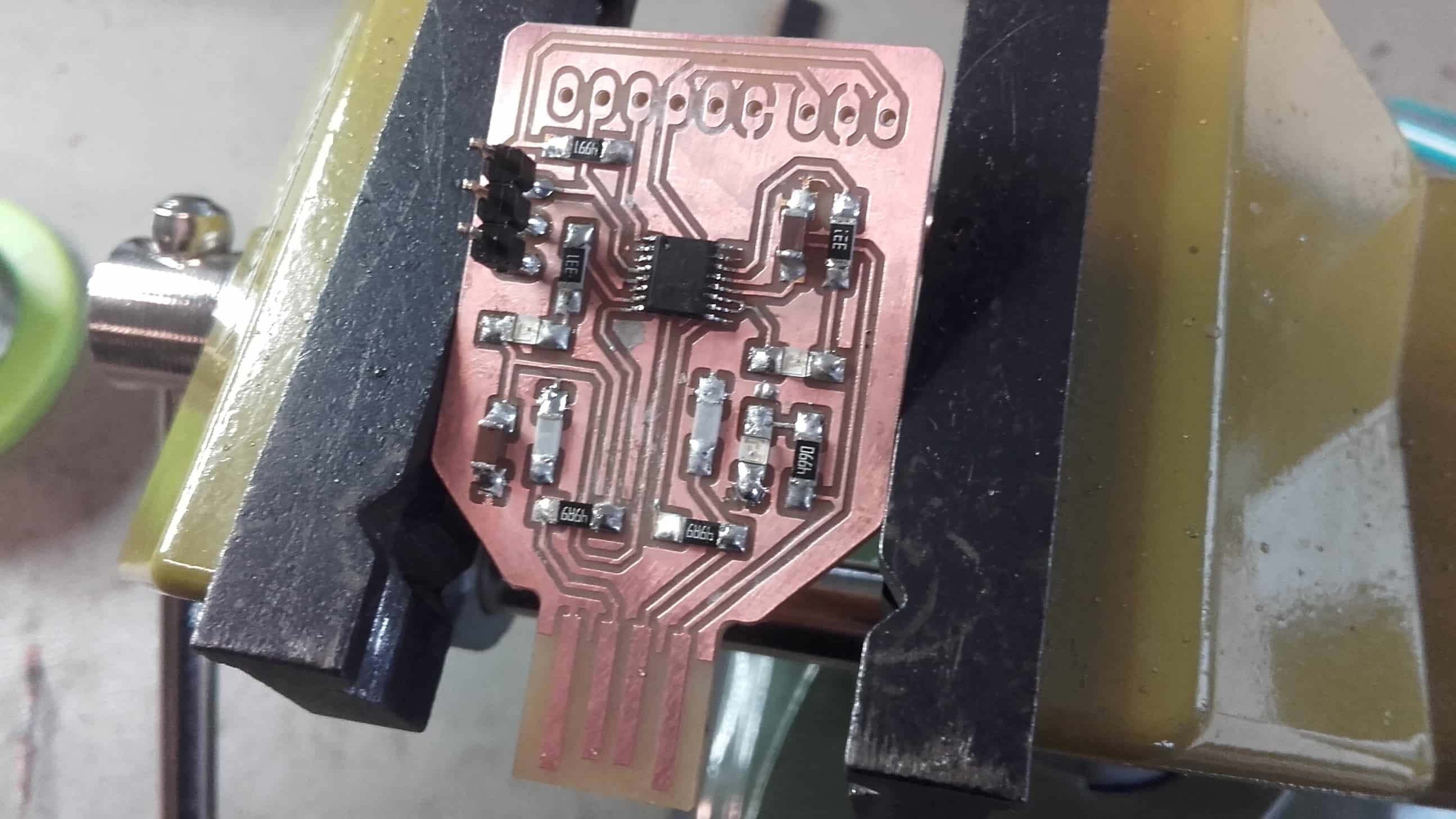
After the processor, the rest of the components were smooth sailing, until I got to the pin headers.
Pin Headers
Apparently they are meant to be soldered from the back, but I didn't know so I struggled to solder them from the front. I got it to work, but it wasn't very pretty in the end.
Testing Functionality
Serial to USB Communication
With it finally finished and populated, it could be tested to see if it actually functions as an in-circuit programmer. When used in the USB to serial converter mode, it has similar functionality to an FTDI cable. This was tested on Rolands laptop and was successfull.
UPDI Mode
When in the UPDI mode, the programmer can be used to program a UPDI target using the serial communication. This has not been tested yet, but should be soon.
Hero Shot
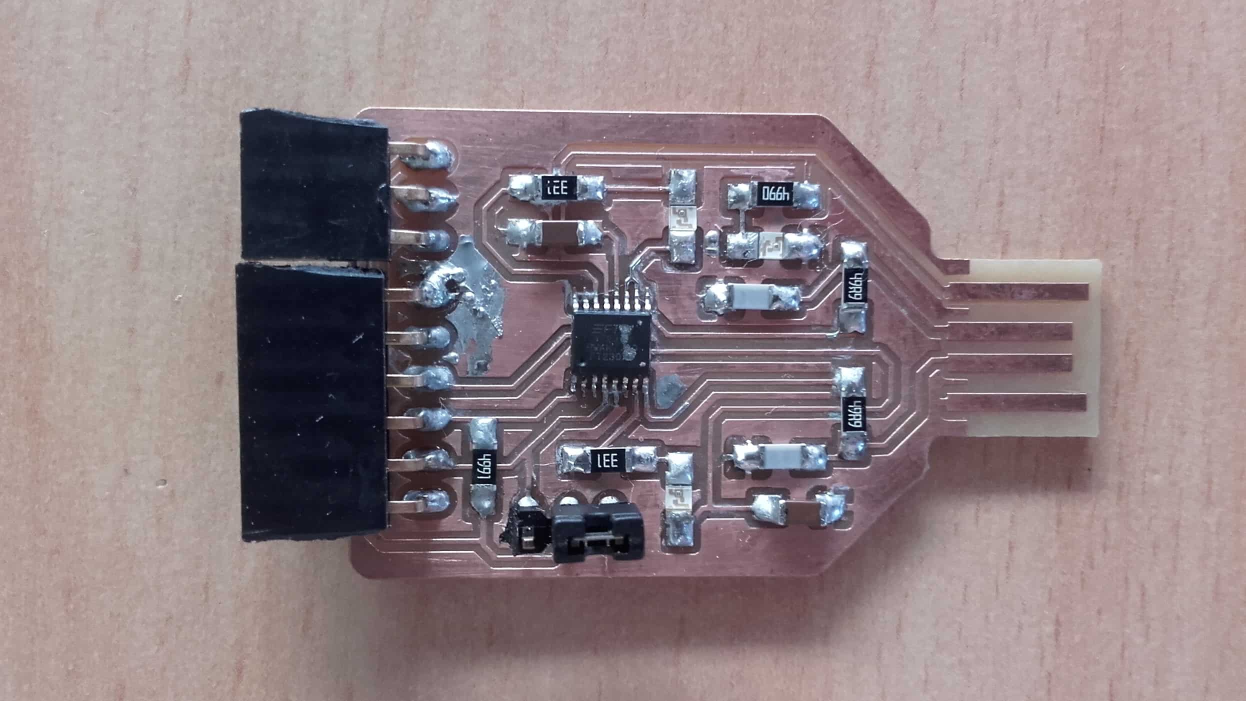
Overall I am very happy that my programmer was a success. Considering that I didn't even know what one was a week ago, I think this project went pretty well overall.
Starting Over
Hero Shots
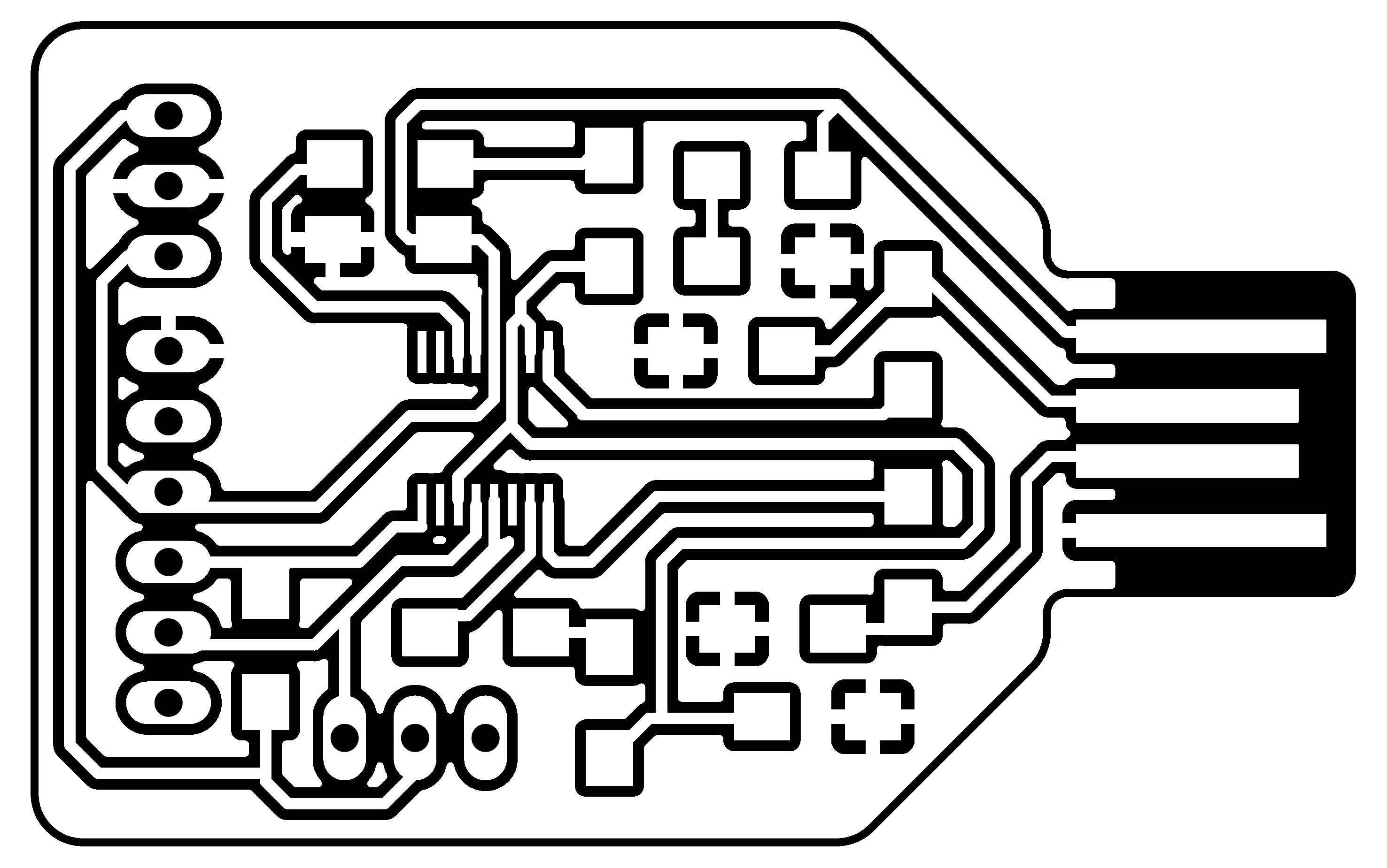
New USBtinyISP Programmer
File Downloads From The USBtinyISP
All of the files for the toolchain I followed are available through the provided links, where I found them. I will only include the files I edited here
Making a USBtinyISP Instead
MODS Traces Parameters
I have no way to test the FT230x-UPDI programmer I made, so I had to make another. I think this is bullshit since we were explicitly told we didn't have to understand what we made for this assignment; we only needed to make it. Oh well. I followed this guide to make a USBtinyISP programmer instead. Apparently it's more complicated to program, but at least I will be able to test it with an Arduino UNO.
MODS Cutout Parameters
I downloaded the images from the website and then opened up MODS. I started by setting up the cutting parameters for the traces and for the cutout. I used the same parameters as I did for the FT230x-UPDI programmer above.
Roland Setup
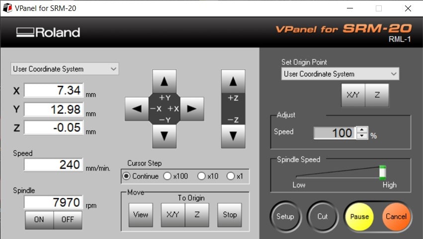
This was my first time using the monoFab SRM-20. I found my zeros and pushed the CUT button to load my gcode.
Cutting
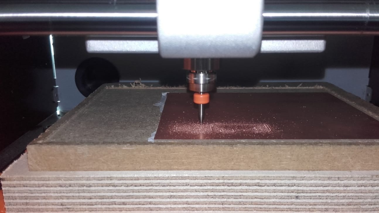
The cut sounded a bit strange to me, but you can't really see inside the case and the traces cut only took about 15 minutes so I just let it do its thing.
No Good
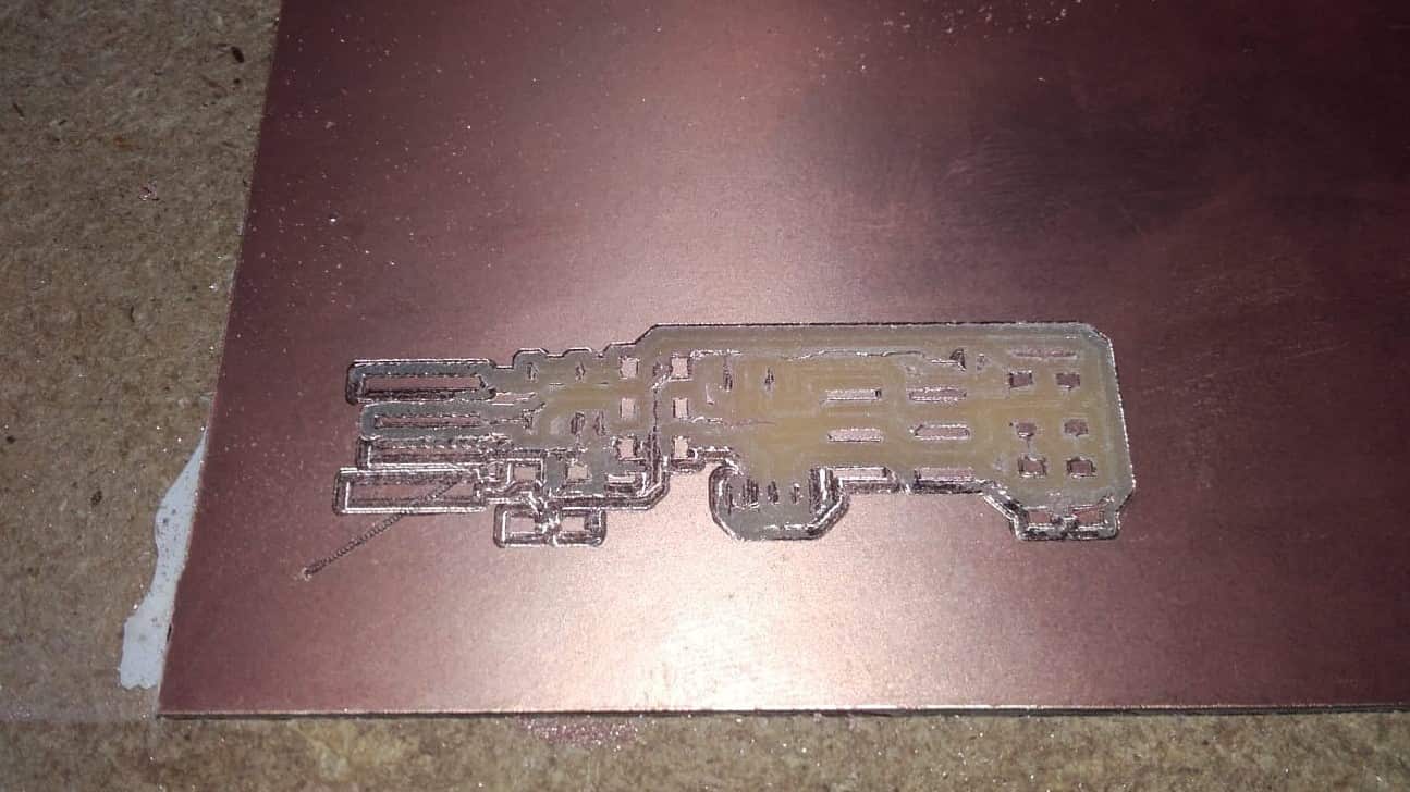
When I was finally able to open up the case, the source of the strange sound became obvious.
Broken Tool
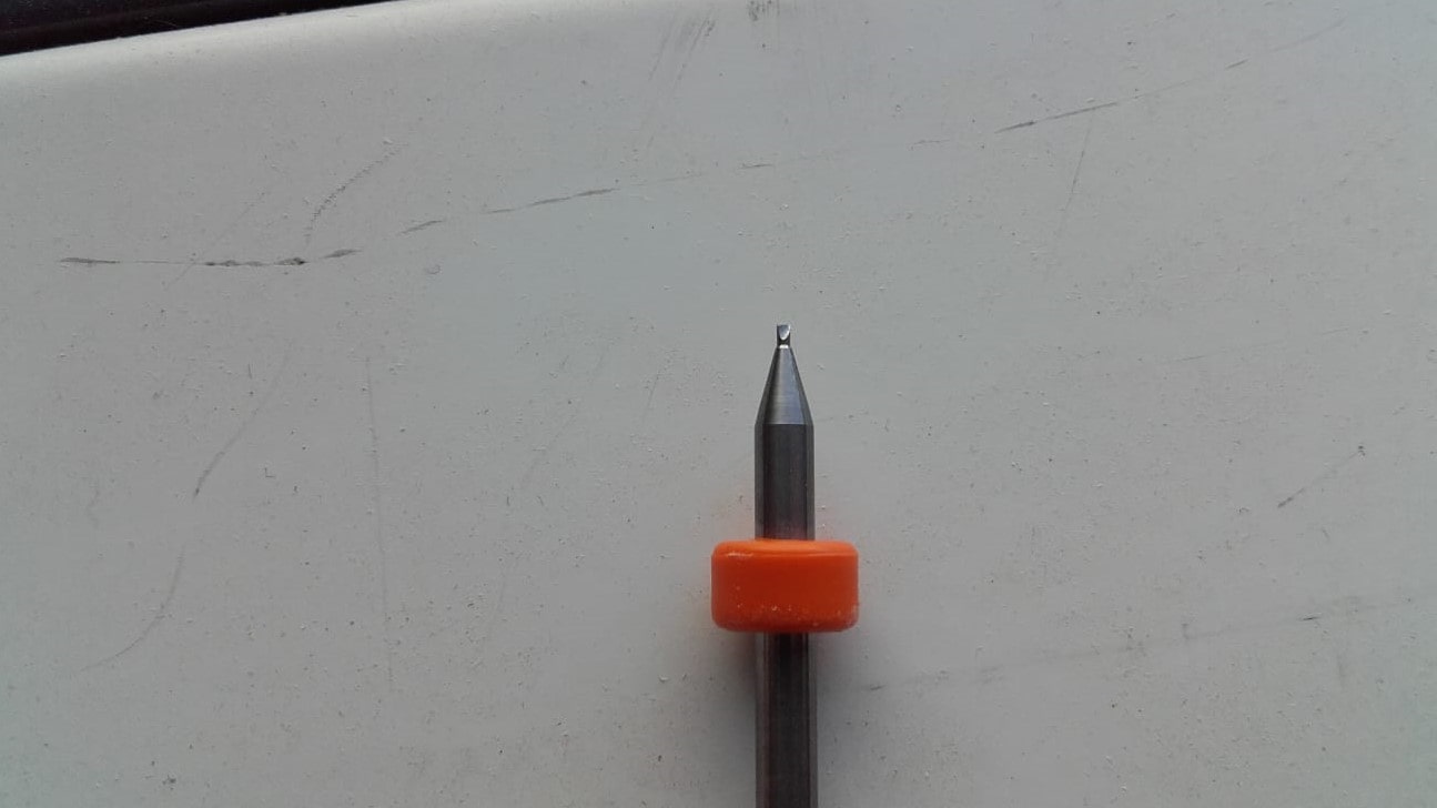
Apparently somebody had put a broken tool back into the box with the new ones and I didn't notice.
Jog Height
I tried again with the same parameters and a fresh tool. The cut went well until the very end when the machine dragged the spindle across the finished work back to the origin, destroying a few traces in its path. That was when I discovered that you have to tell the gcode to raise the spindle for the jog height. I changed the module in MODS and tried a third time.
Success
This time, things finally went according to plan. I made the same adjustment to the gcode for the cutout and finished the milling. Not counting the mistakes, the milling only took about 25 minutes and was pretty decent quality, but the dark case on the Roland that you can't open is annoying. I also prefer Candle, to the SRM-20 GUI. The Genmitsu is still my favorite for now.
Cleaned Up
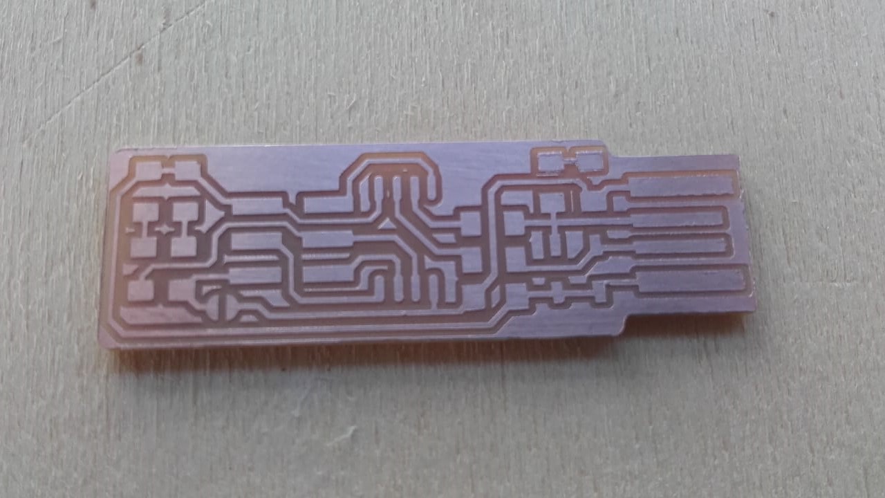
I cleaned up the board with some steel wool.
Ready to Stuff
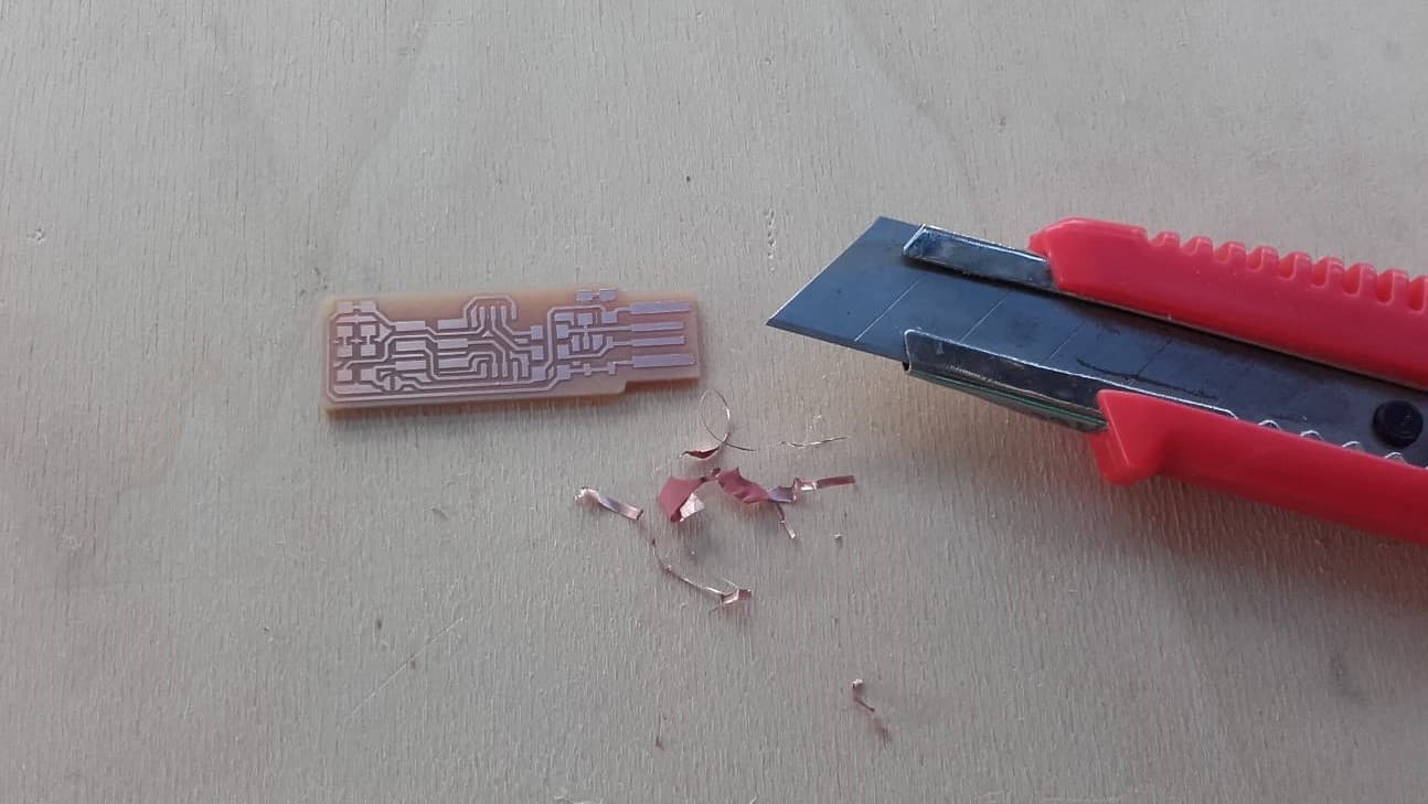
And then removed some of the extra copper with a box knife.
Components
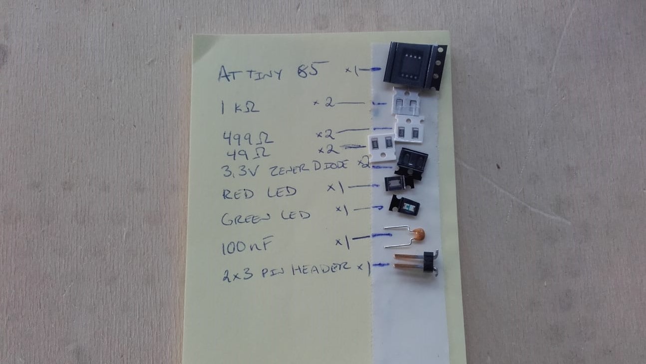
Fortunately I was able to find everything in the lab so I didn't have to order anything. I decided to go with the ATtiny85 since we are out of the 45s. I also could't find any 100nF SMD capacitors so I had to use a through hole one, but oh well.
Final Result
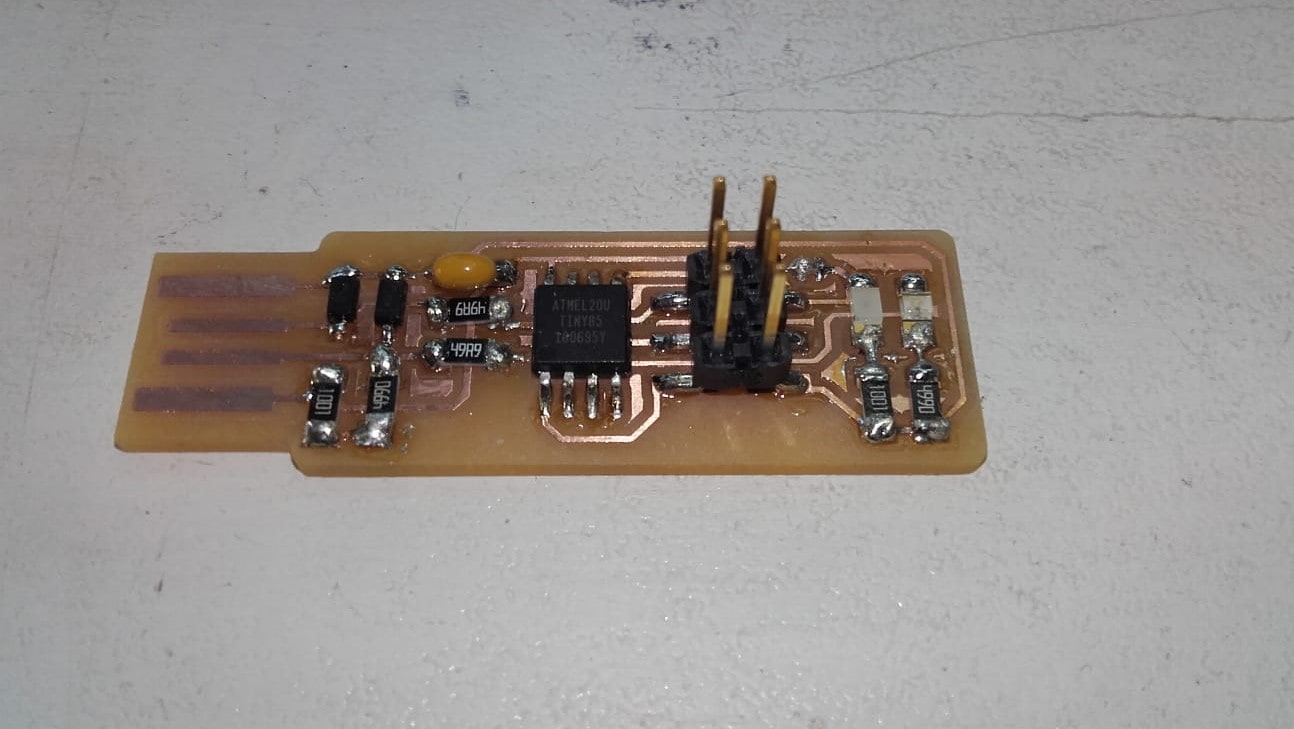
After a bit more soldering, I had the board stuffed and ready for programming. I think it turned out alright in the end. I am definitely getting better at soldering since doing my final project.
Programming the Programmer
AVR GCC for Windows
 -->
-->
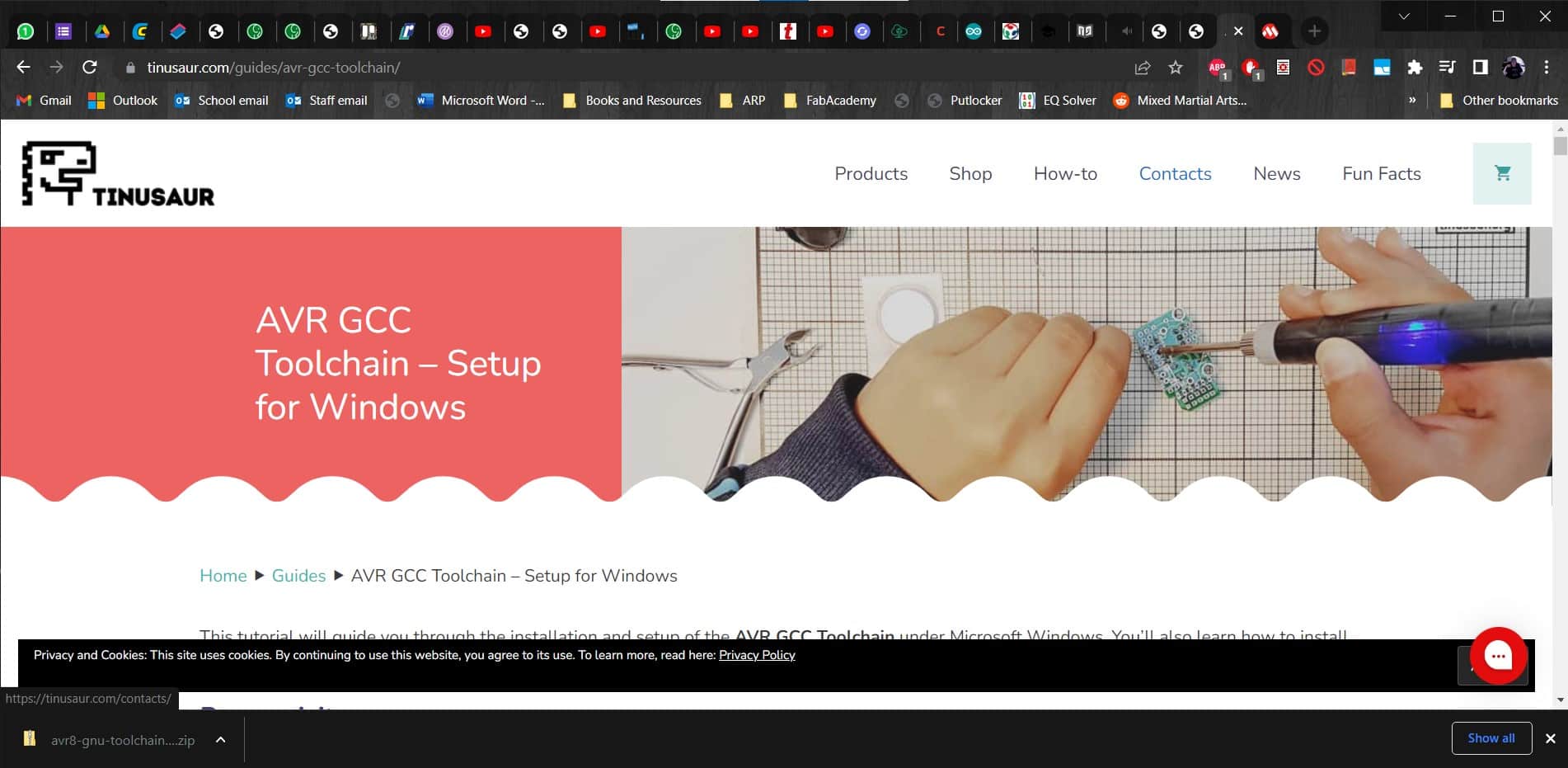
At this point in the guide, I got sent over to another guide, this one for the AVR GCC toolchain. I followed the instructions to make a AVRGCCStart.cmd file and then made my way through the rest of the steps.
No Error
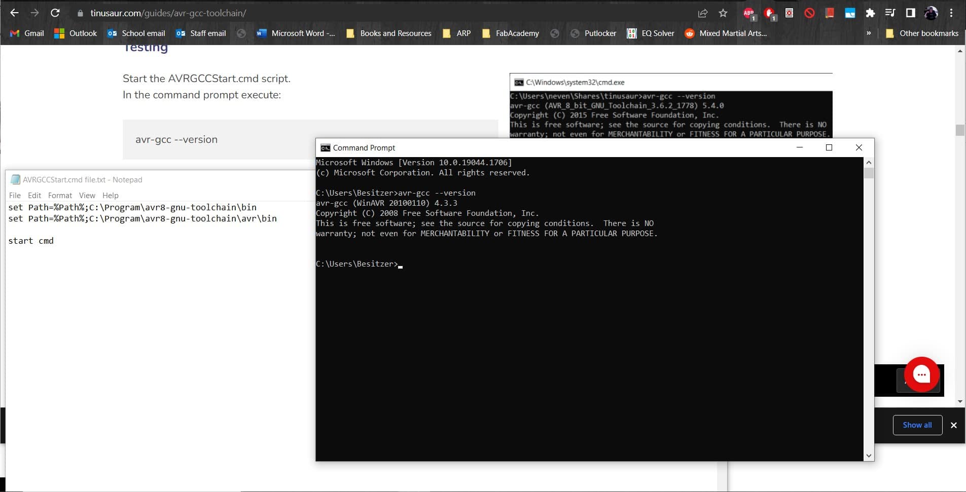
Then in the command prompt, I ran avr-gcc --version. I didn't get an error so proper installation was confirmed.
Make
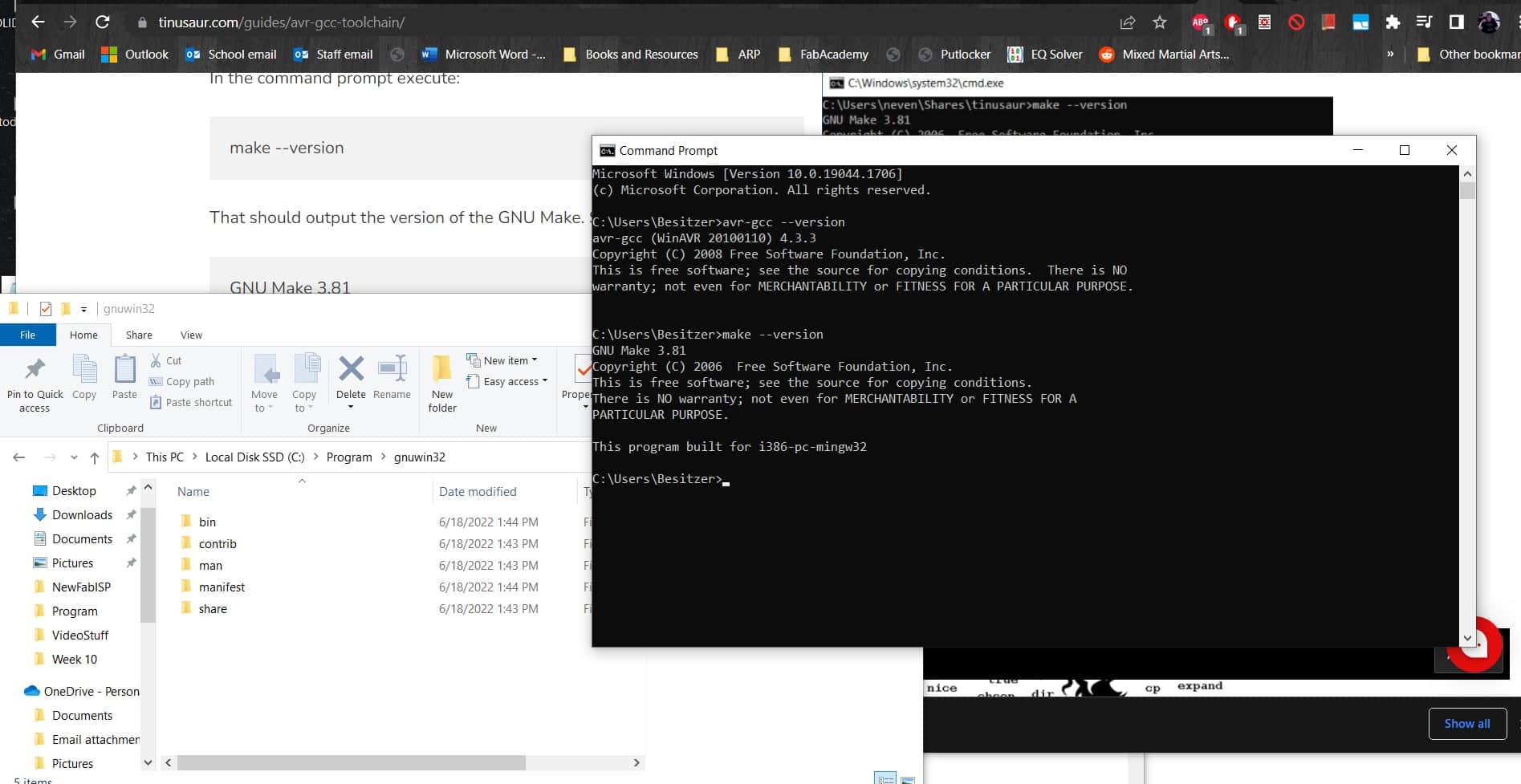
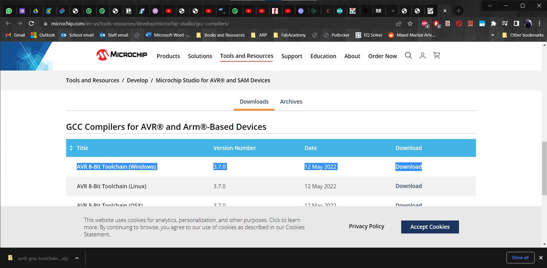
Then I downloaded the binaries and the dependencies zip files from the Make Package and the used make --version to confirm installation again.
CoreUtils Package
Then I got the binaries and the dependencies zip files from the CoreUtils package and installed those.
Steps 5-17...
Followed by AVRDUDE. Then I downloaded the libusbK-3.1.0.0-bin.7z file and copied the libusb0.dll file over to my AVRDUDE folder after checking the digital signature.
Firmware Update
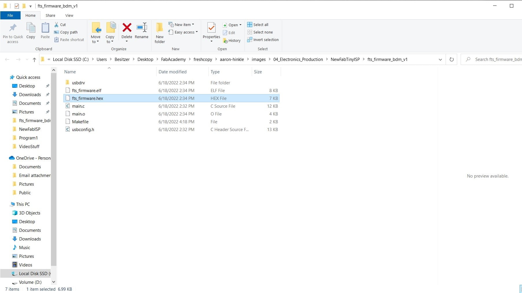
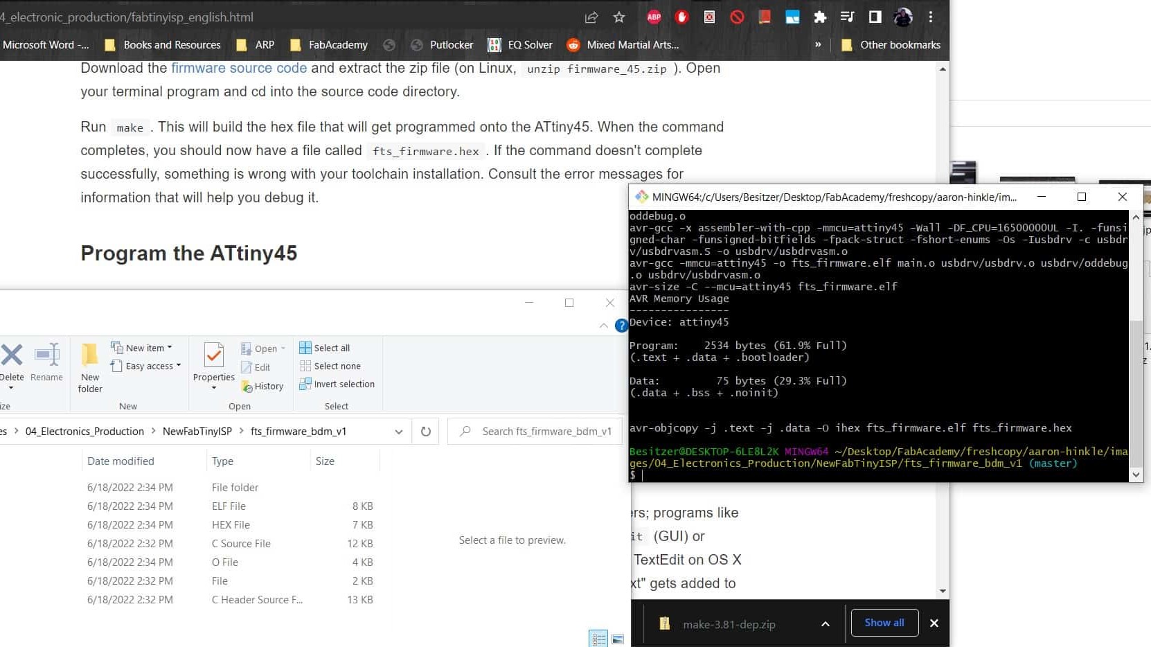
I followed all of the instructions in the guide down to the point of programming the programmer since they used a USBasp programmer and I wanted to use an Arduino UNO. So I switched over to this guide again to make my way through getting and building the firmware.
USB Works
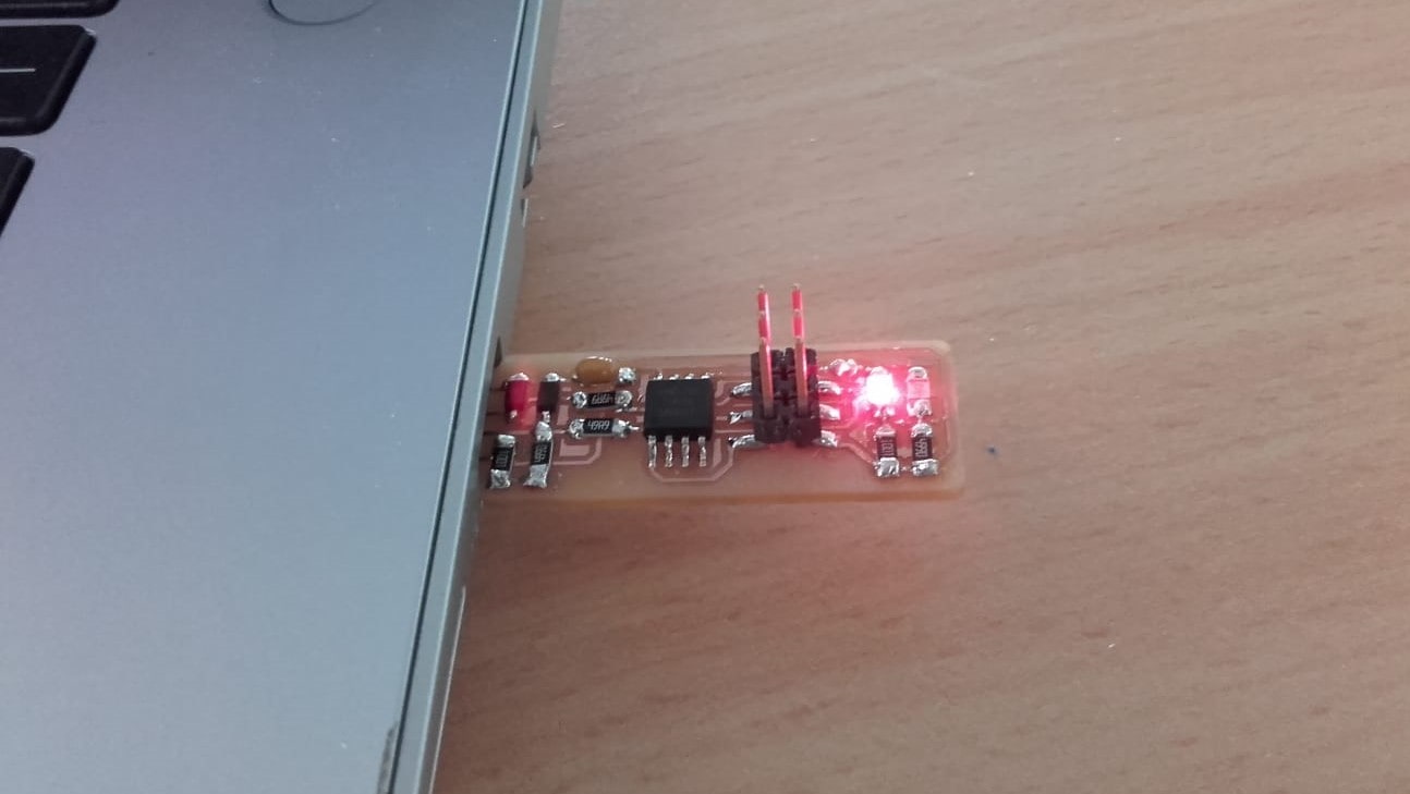
Finally, I tested the USB functionality and was ready for programming the board.
Roland to the Rescue
I tried everything I could find on the guides and on several forums, but I just kept getting errors I didn't understand. Finally I switched over to Roland's documentation for his Embedded Programming Week for some more local help since he already did exactly what I am trying to do.
Programmer Type
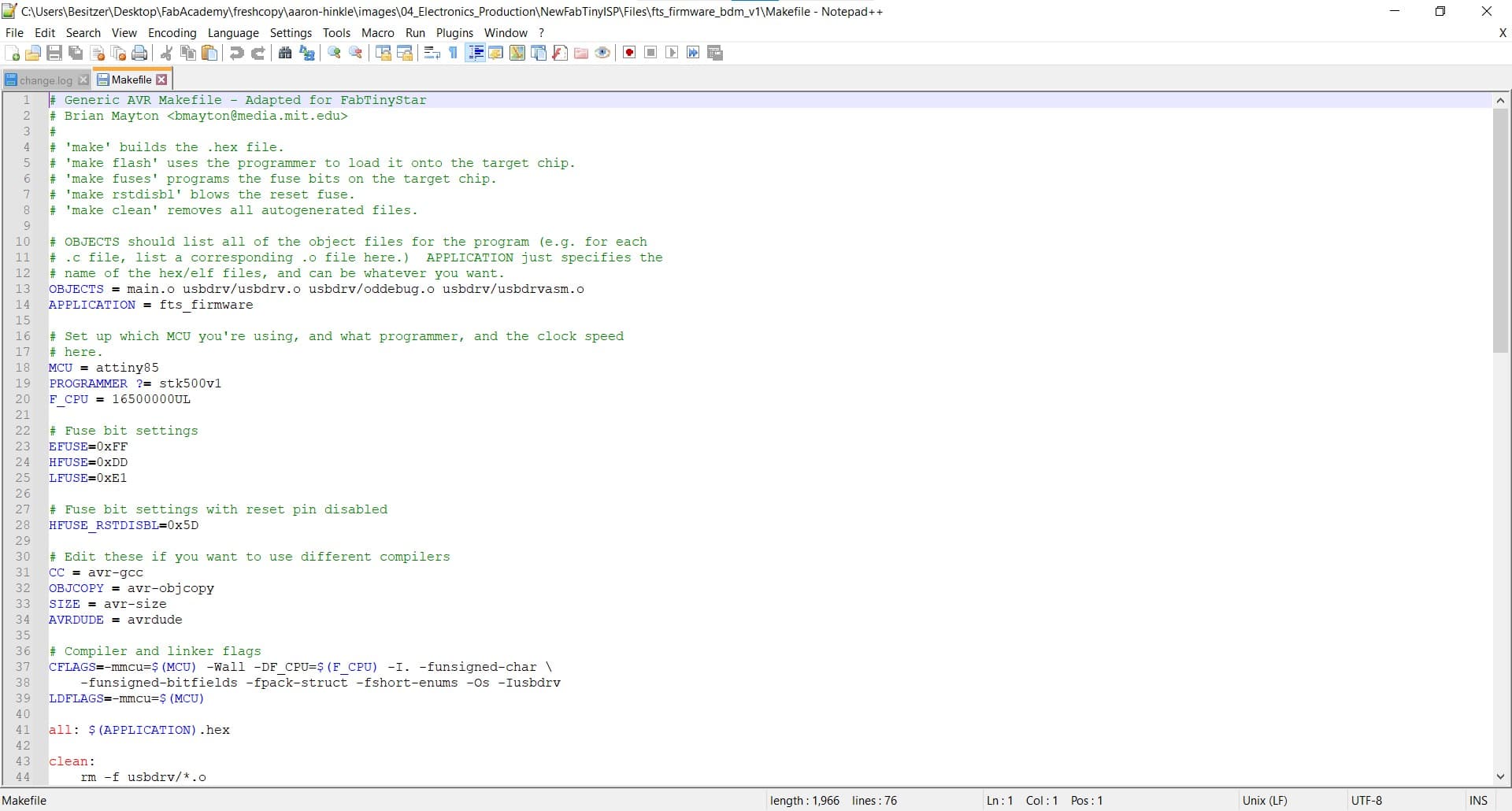
Roland's page helped me figure out how to edit the Makefile. The first thing I had wrong was the programmer type. Apparently, when you are using the Arduino as an ISP programmer, the type is stk500v1. Good to know!
Adding COMs and Baud rates
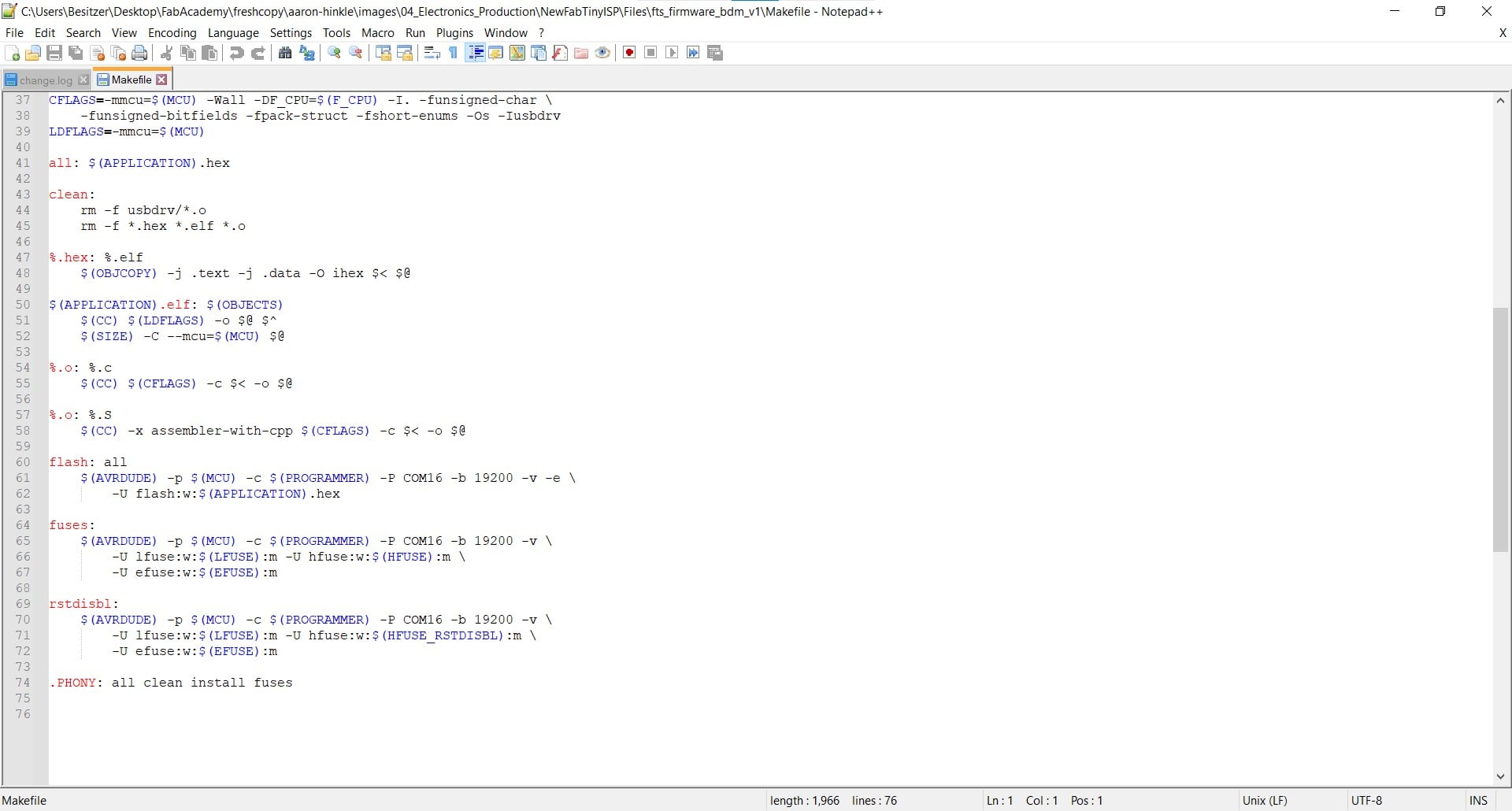
I also needed to add the information for the port and the baud rate to the fuse declarations.
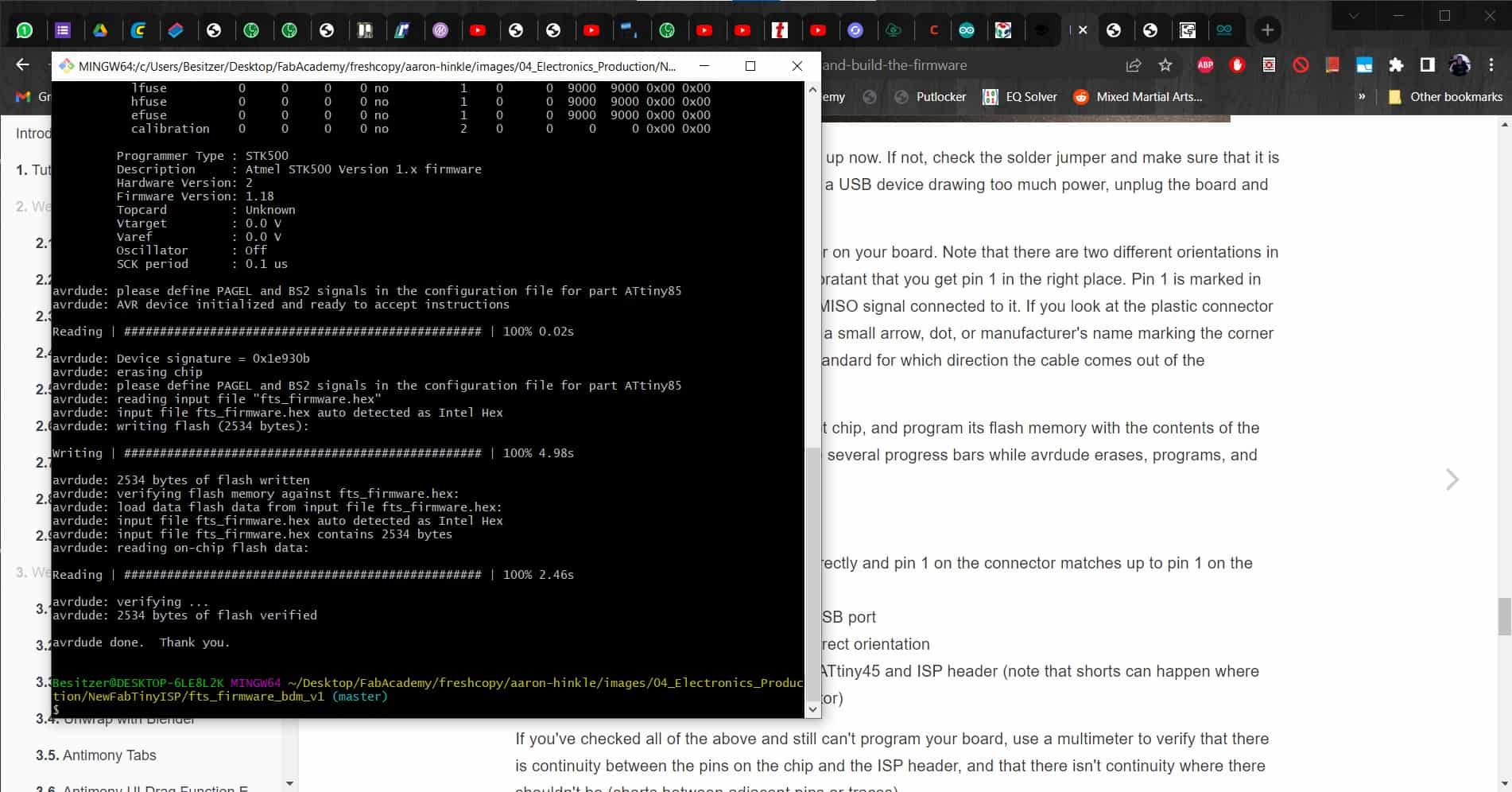
Finally!
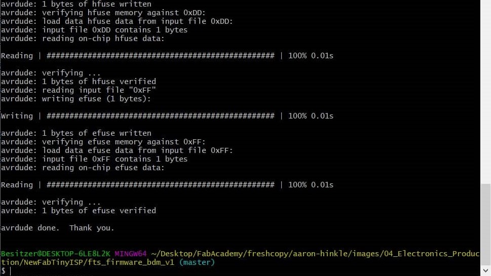
Once the firmware documents had all been added and edited correctly, I was finally able to flash the programmer, upload the ISP programmer program, and burn the fuses so it would now be an ISP programmer forever.
Success
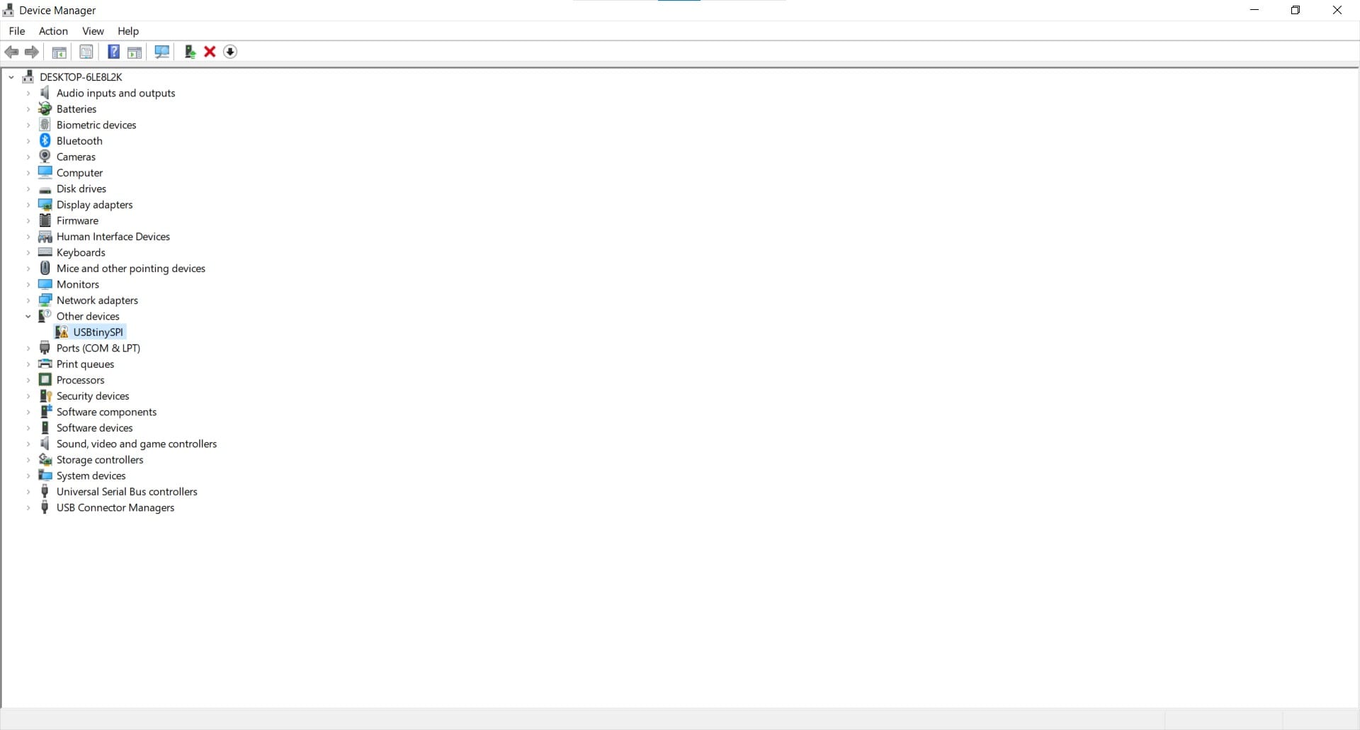
I finally had a device that my computer recognizes as an ISP programmer (even if it does have an unexpected name?)!
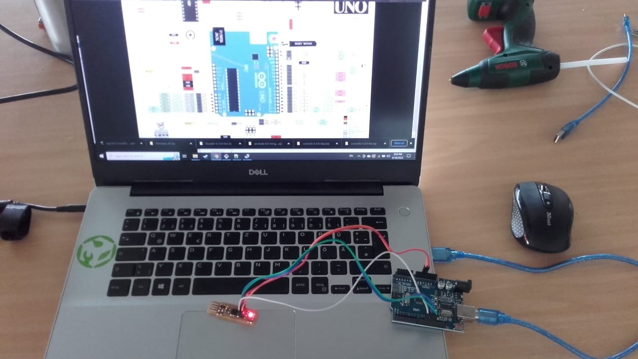
Testing the Programmer
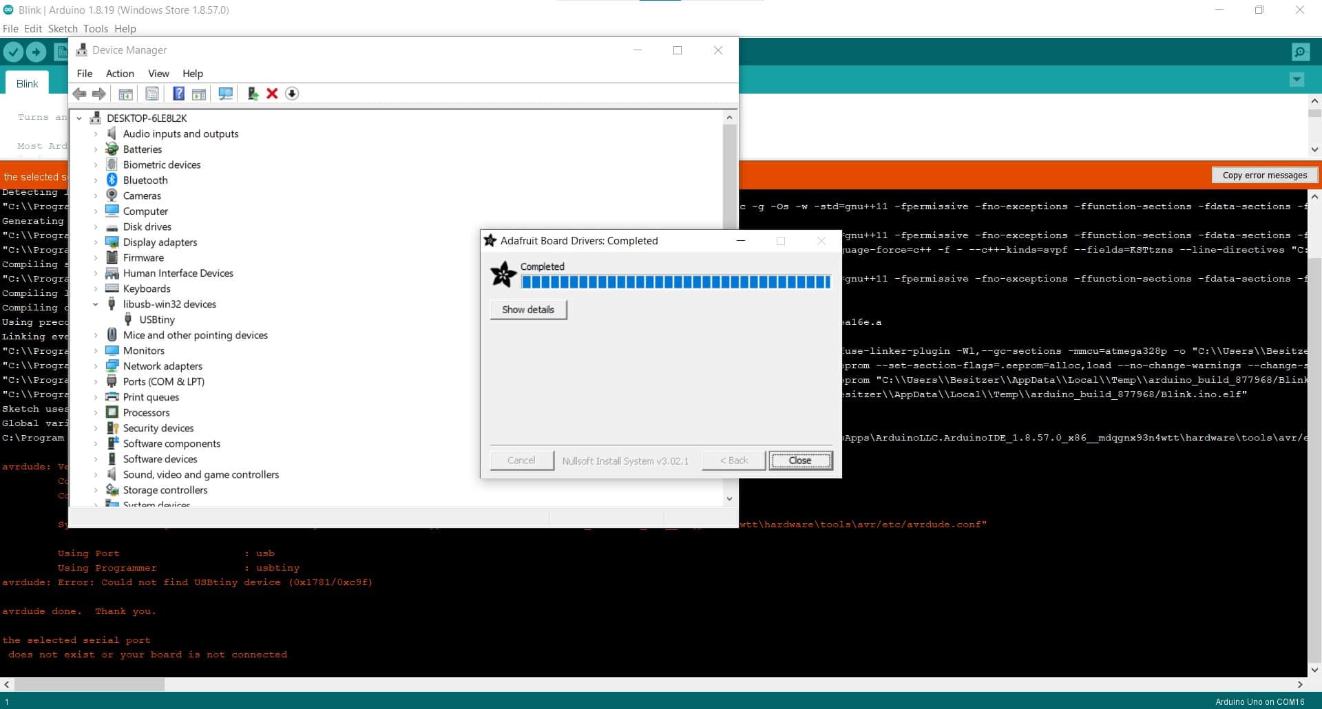
Blink
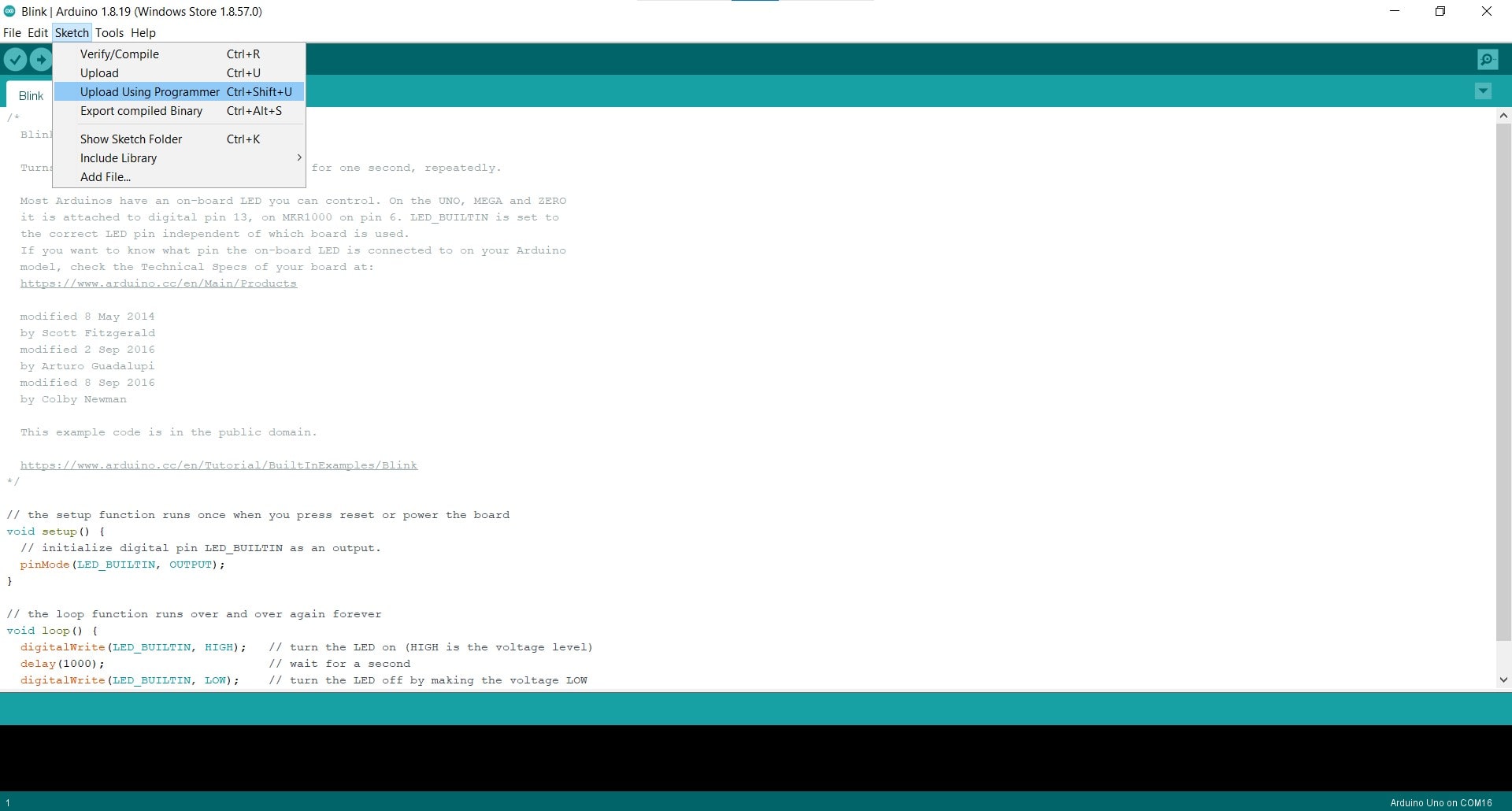
For a test, I decided to just see if I could upload a Blink sketch to an Arduino. Of course, the first try failed...
.nc)
.nc)
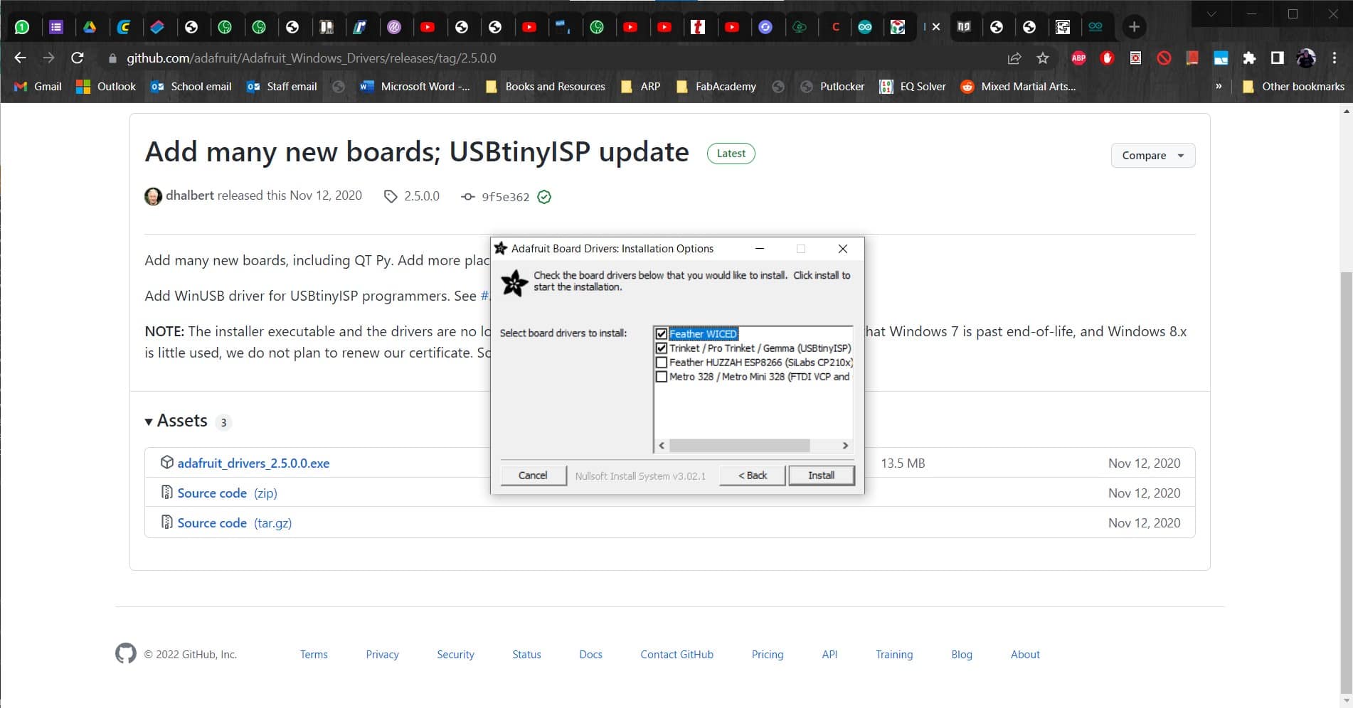
Installed
I got them downloaded and installed.
Done Uploading
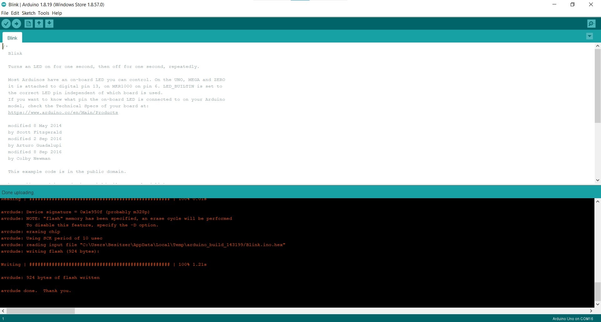
And then FINALLY used my new ISP programmer to upload a sketch to an Arduino Uno.
Hero Video
This programmer was easy to make, but quite complicated to program due to the workflow for Windows. For anybody thinking about making one, I definitely recommend using another workflow if the option is available.