12. Mechanical design/ Machine design
We are halfway there! The Mechanical design & Machine design weeks just arrived! We had two weeks to design and build together a machine, using the techniques we learned during this program. Please visit our project page to see more details.

Our team was composed of 5 students (Edgar, Juan Carlos, Katrina, Jorge and me) and 2 instructors (Silvia and Abdón) who helped us during the whole process of building the machine.
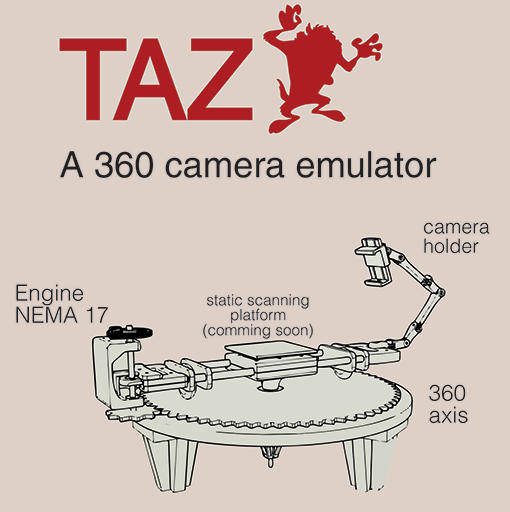
After a brainstorming session, we decided to fabricate a circular camera slider. It basically consists in a camera holder that rotates with the help of a Nema 17 stepper motor. If the camera is pointing to the center of the machine, it could be used for scaning objects. Otherwise, if the camera points in the oposite direction it could be used for panoramic 360 photos. Our machine is called “TAZ” because it spins, just like this looney tunes character.

I was in charge of the design and fabrication of some components of the base structure of the machine, including the main gears.

The base structure was designed by Edgar, but I was in charge of cutting his design on the Shopbot. We used a 20mm plywood sheet for this component. The fabrication process consisted in 4 steps:
- 2mm pocket to decrease the plywood sheet thickness to 18mm.
- 6mm circular pocket on the center of the component.
- 12mm Profile on the center of the component to add a hole.
- 18mm Profile to cut the shape of the base component.

The bigger gear is composed of two sheets of MDF, 3mm each. The laser cutter was used for cutting this component. Also, an additional 3mm circle was cutted. Then, we used some glue to keep the base structure and the gears togheter.

Then, I designed three legs for the base structure which were based on the table legs I fabricated during the Computer Controlled Machining week. Silvia helped me to cut this part in the Shopbot and then Edgar assembled the components.

Additionally, I helped Edgar to design the smaller gear, which would be connected to the stepper motor. After testing different numbers of teeth we decided to use 10 of them. I modified the design and fabricated the gear using the 3D printer.
The rest of the team worked on designing and fabricated the rest of 3D printed parts. Edgar assembled most the most part of the machine and loaded GRBL into the circuit board. In the meantime I took photos and recorded videos of the process… The following video shows the fabrication process:
Finally - on the last day - I installed Universal Gcode Sender into my laptop to control the machine and perform the final tests. Bellow are two videos that show the machine in action:

Gallery


