3D Scanning and Printing

3D printing or additive manufacturing is a process of making three dimensional solid objects from a digital file. The creation of a 3D printed object is achieved using additive processes. In an additive process an object is created by laying down successive layers of material until the object is created. Each of these layers can be seen as a thinly sliced cross-section of the object. 3D printing is the opposite of subtractive manufacturing which is cutting out / hollowing out a piece of metal or plastic with for instance a milling machine. 3D printing enables you to produce complex shapes using less material than traditional manufacturing methods.

Assignment:

  • Group assignment
    • test the design rules for your 3D printer(s)
  • Individual assignments
    • design and 3D print an object (small, few cm3, limited by printer time) that could not be made subtractively
    • 3D scan an object (and optionally print it)


    Starting


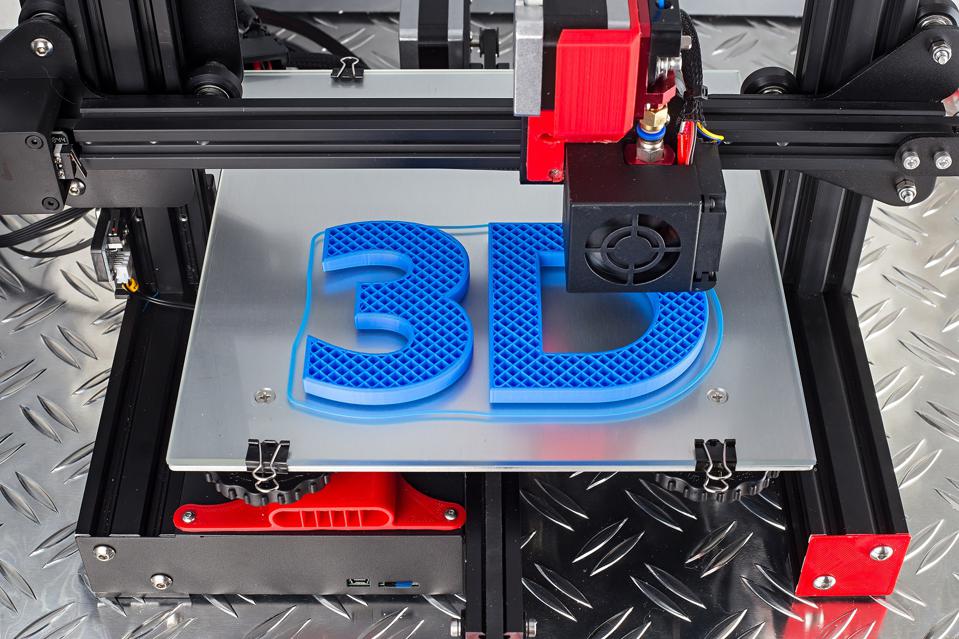
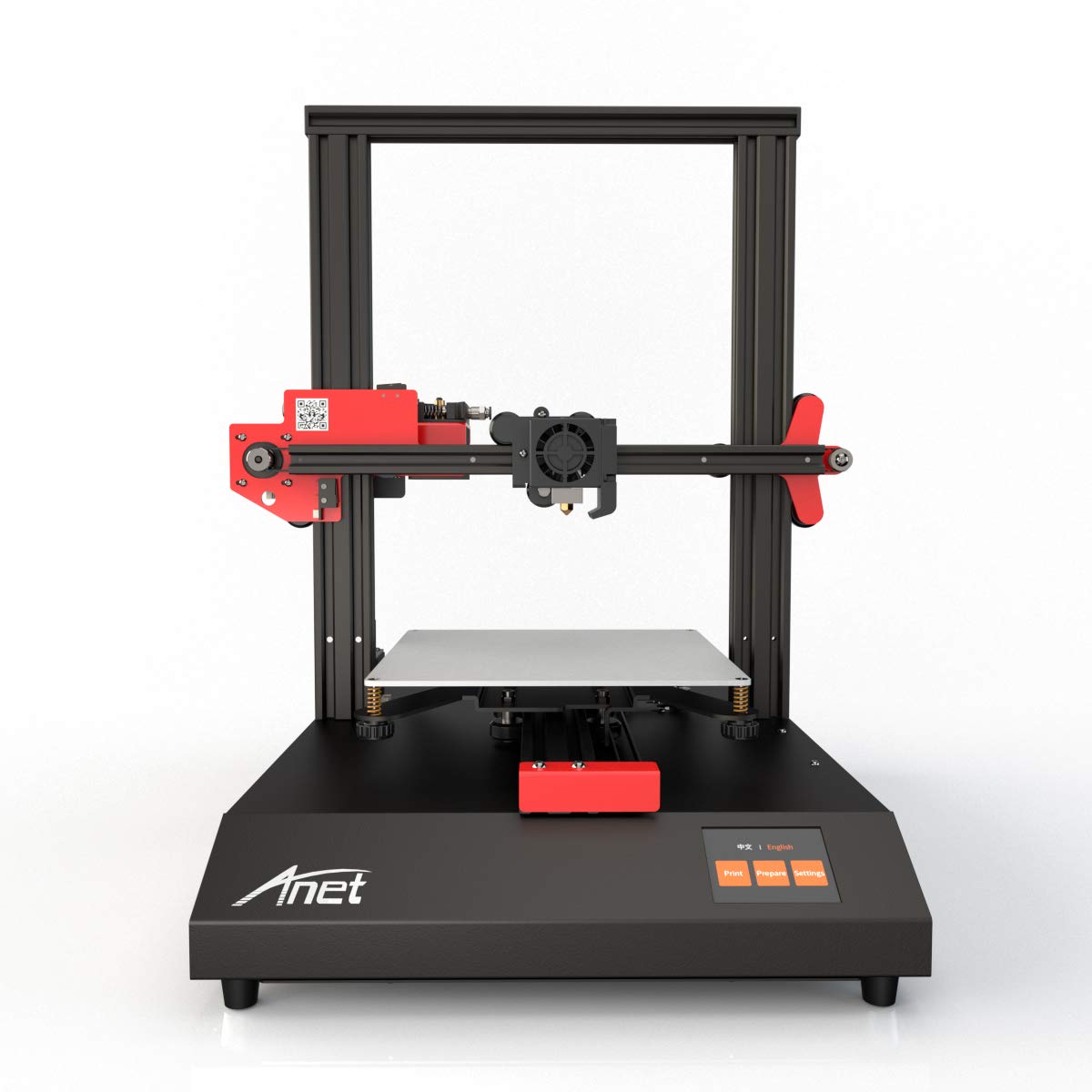
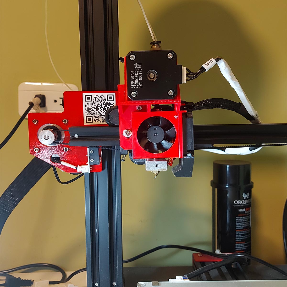
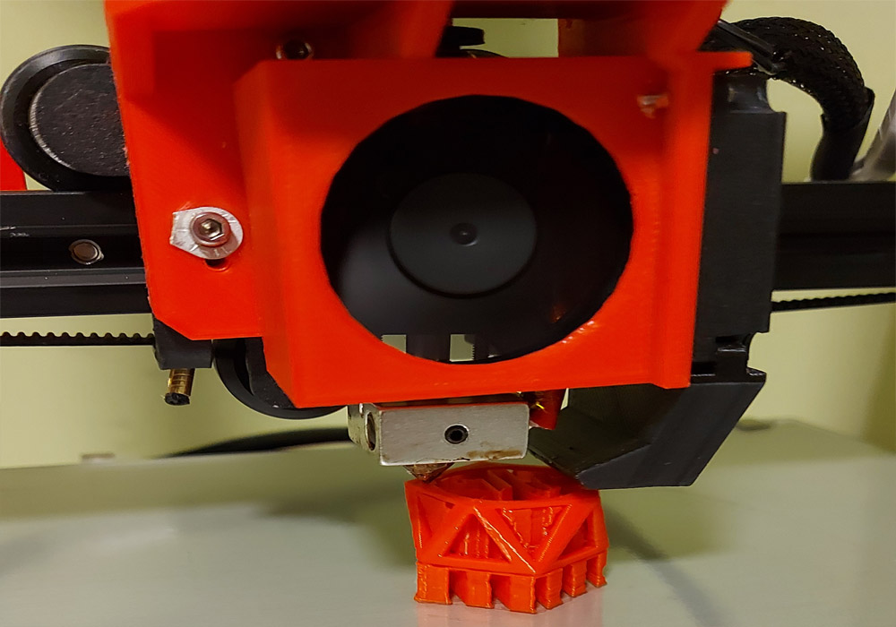
    Testing the 3D printer

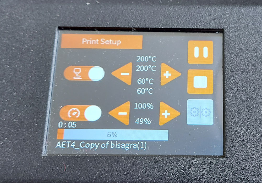
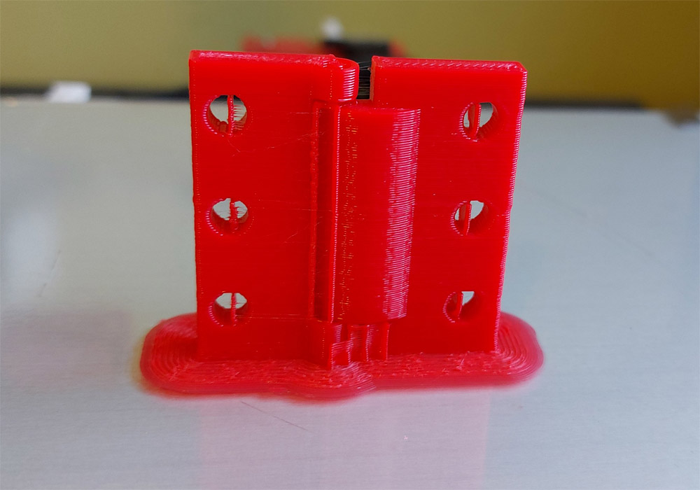
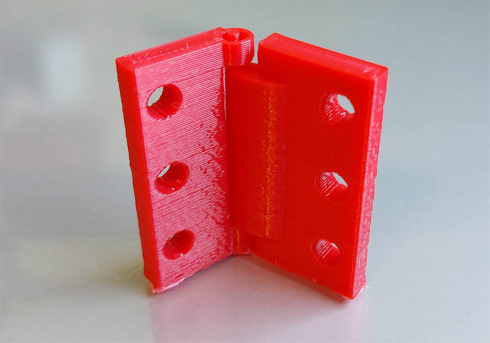
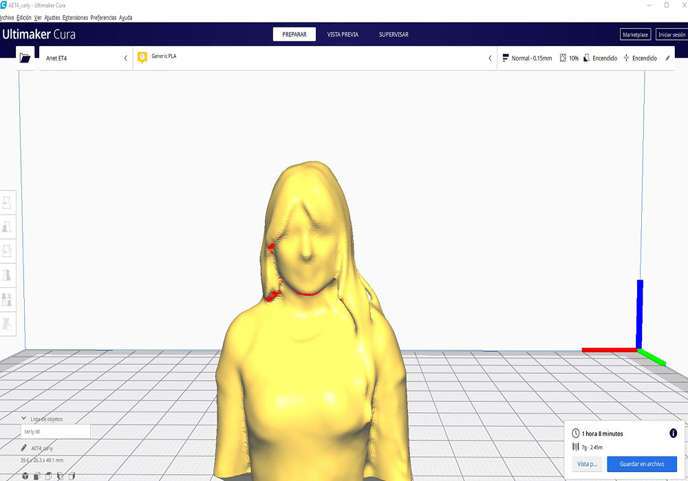
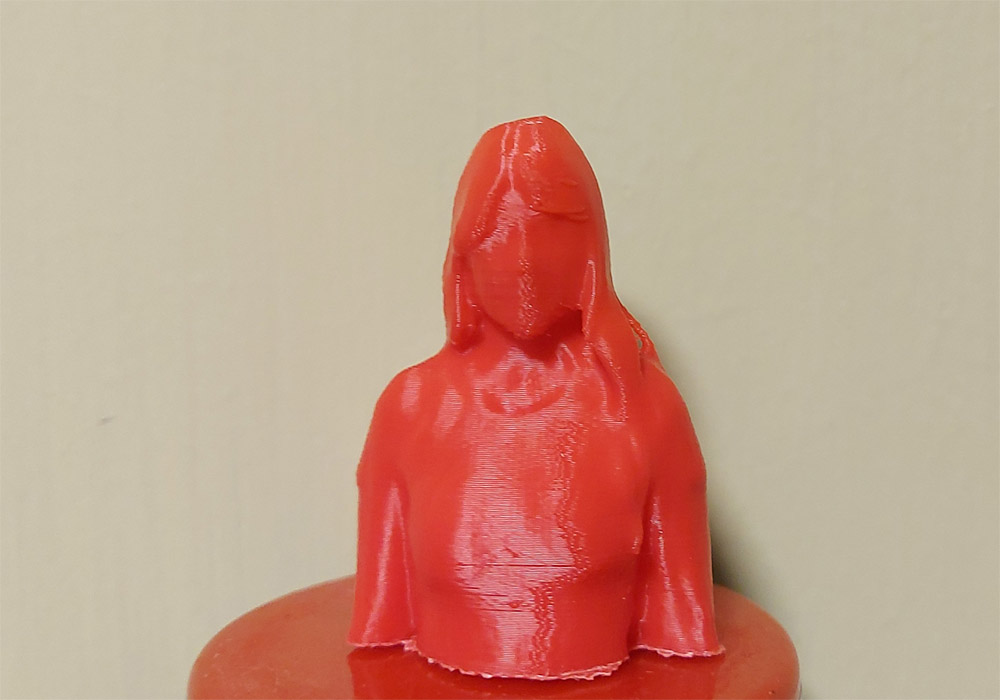
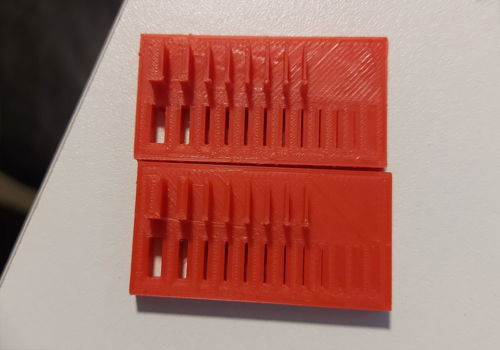
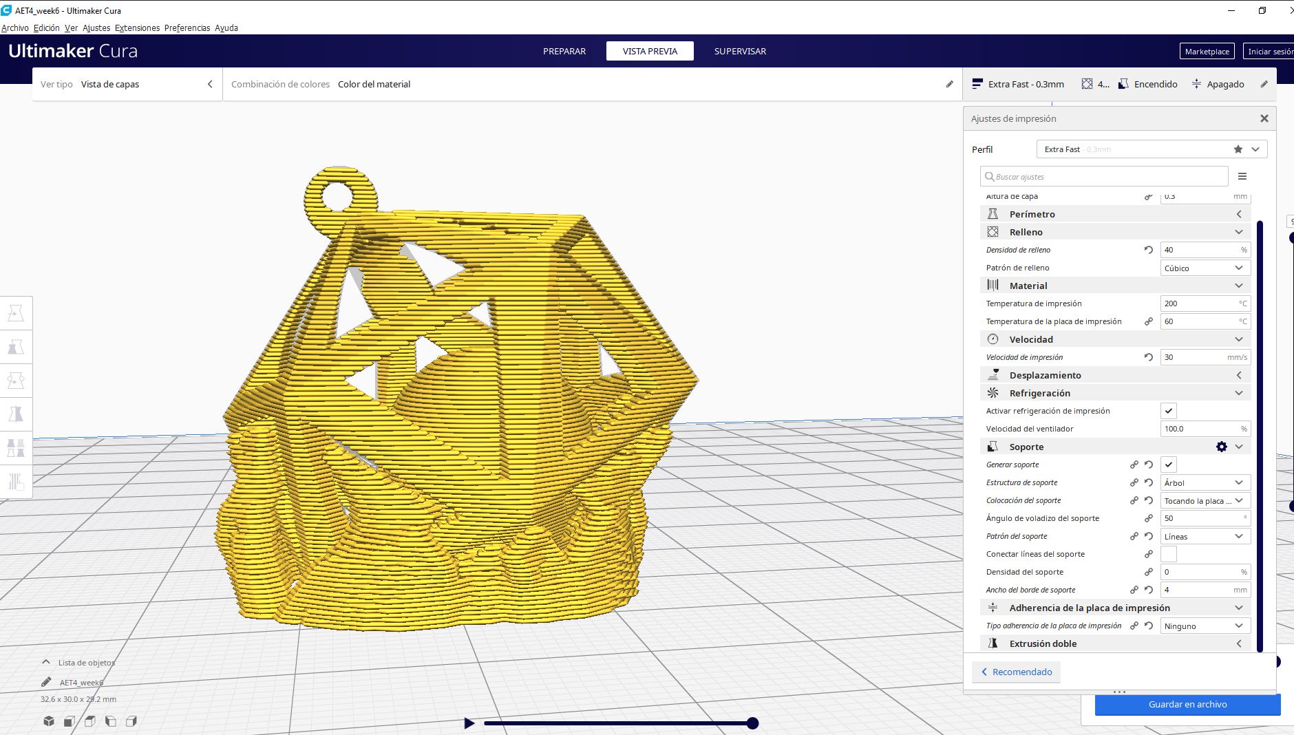
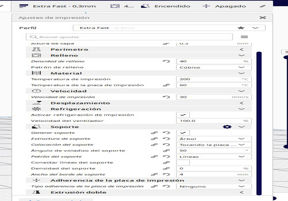
    When testing the different printing parameters such as: temperature, speed, layer height, among others, I could understand the importance of these in the final product, the quality of the printing will be severely affected and each parameter directly affects the other. in print quality. If we want a better print quality that will take much longer to print.

    file download

    line Test


    Another useful test


    Practice in TINKERCAD


    Design and 3D print an object (small, few cm3, limited by printer time) that could not be made subtractively.


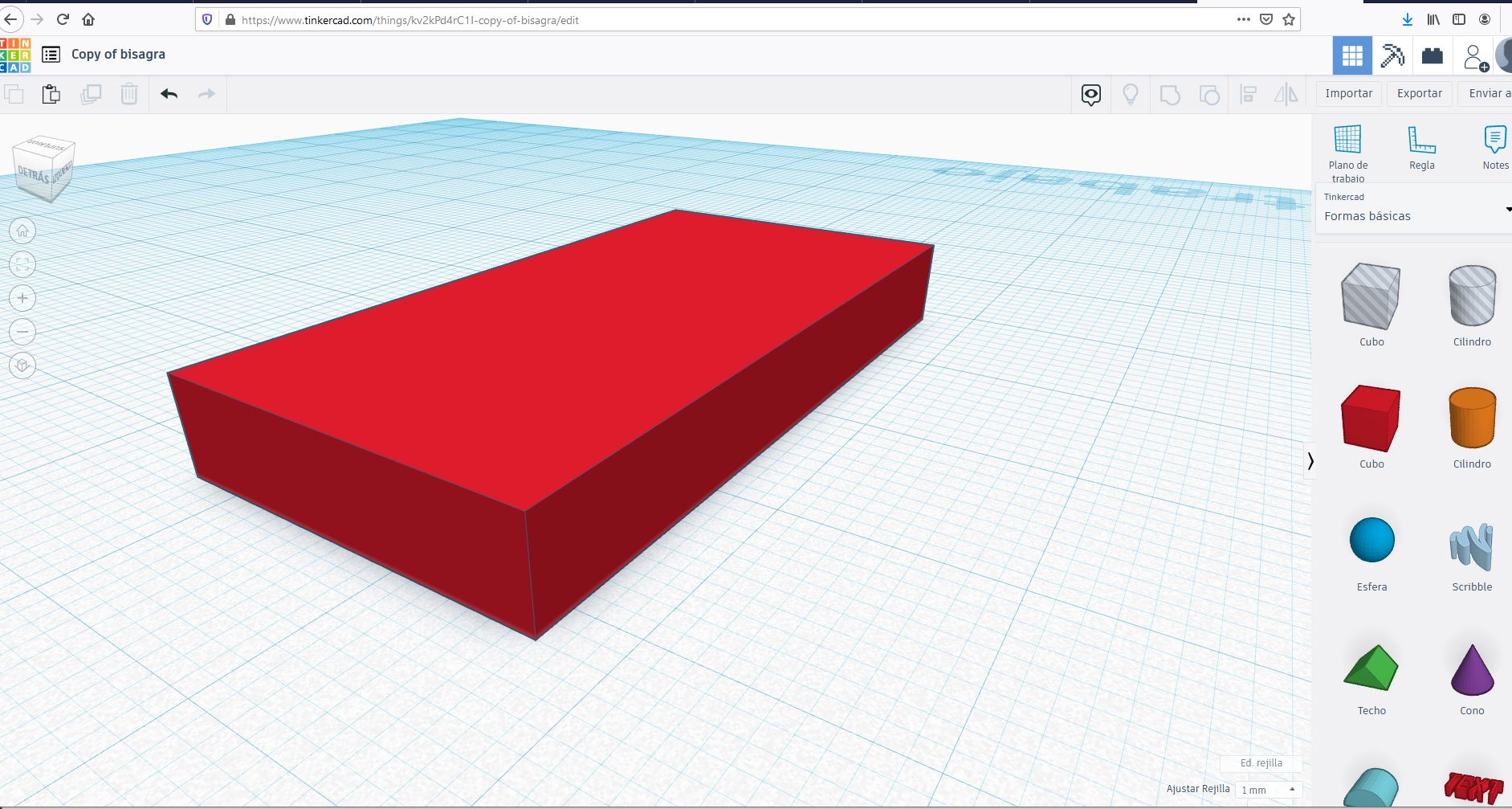
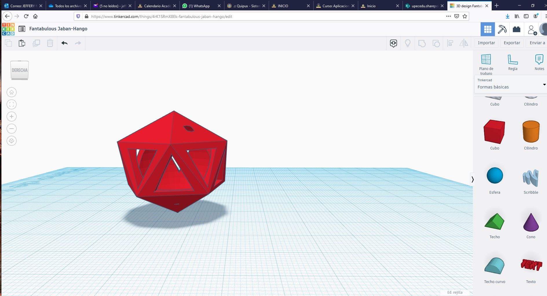
    For this practice I will try to print a figure with several edges that contains a sphere inside, for this I will use Tinkercad to make the model to print


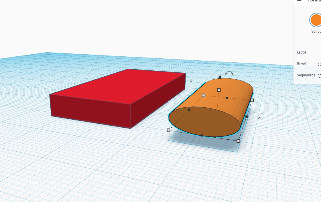
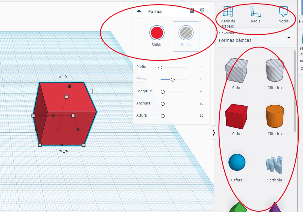
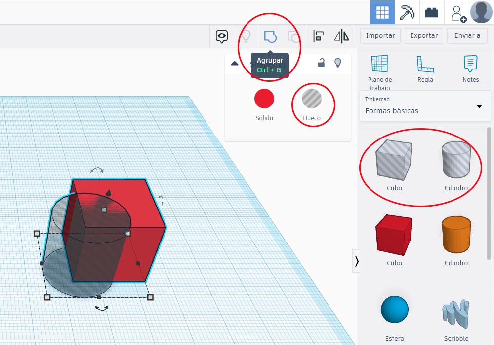
    Tinkercad is a very intuitive and easy-to-use tool, on the right side we have several basic shapes, texts, characters, numbers, connectors among others, in the upper right we also have some tools that help us group shapes, align and duplicate


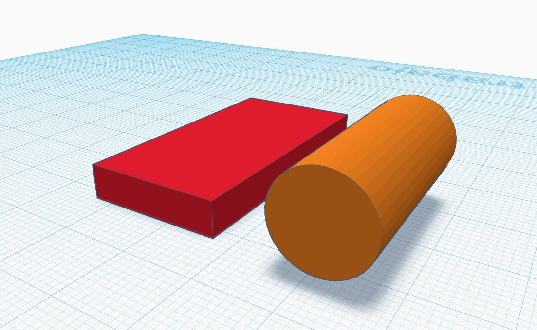
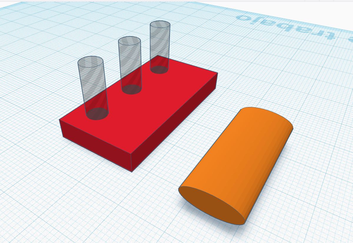
    In TinkerCad imagination is very important, being able to visualize the final result from basic shapes, for example we can place a cube and inside it a hollo cylinder, then we can group the figures and we will obtain a cube without the cylinder part


    TinkerCad also allows us to manipulate all the dimensions of the figure that we are editing


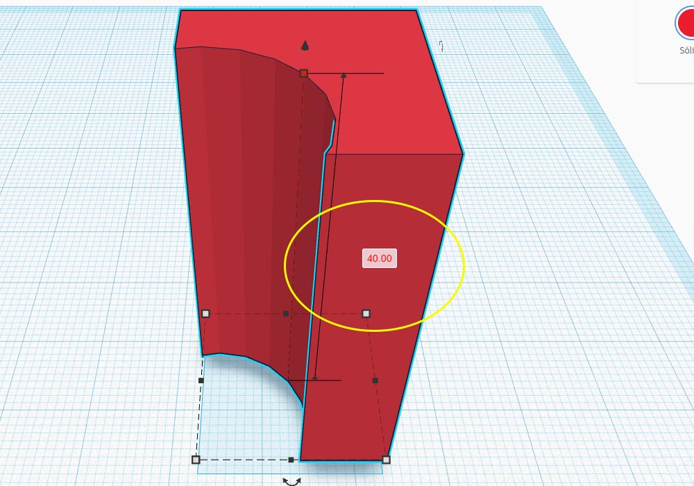
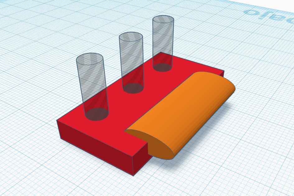
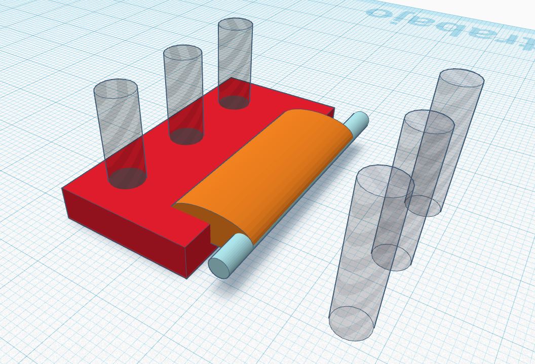
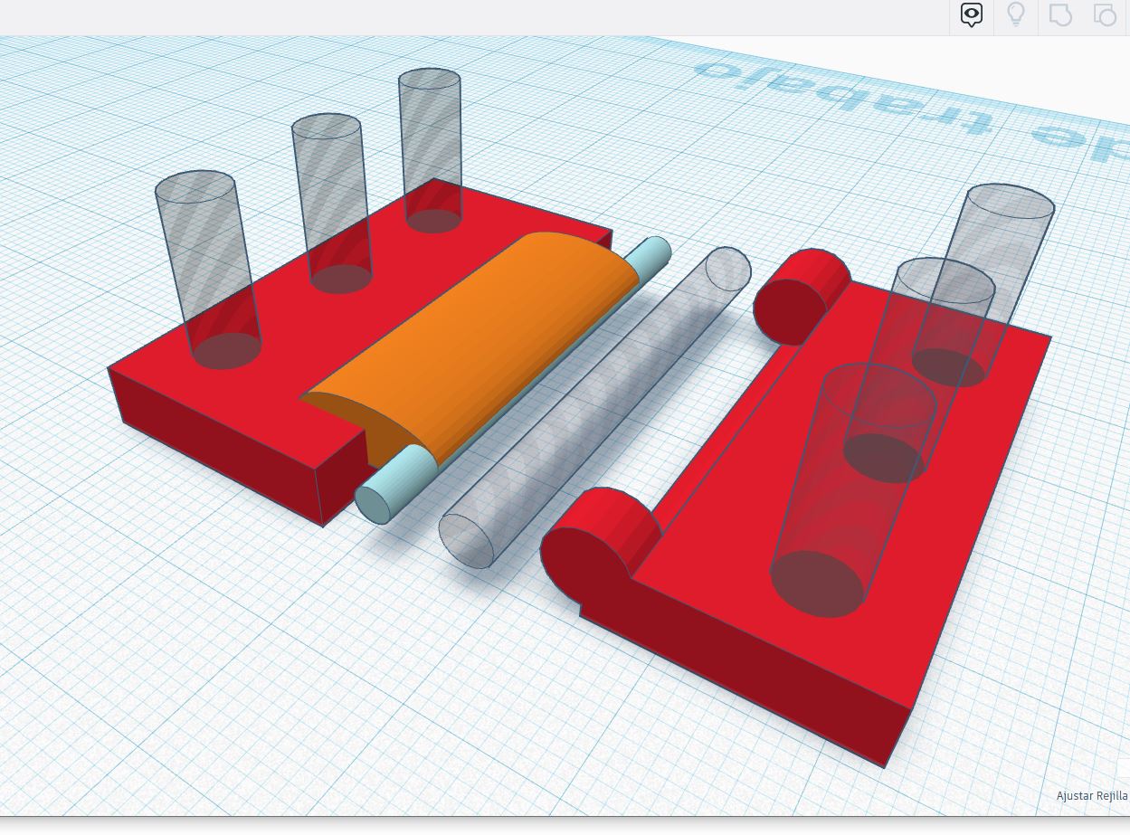
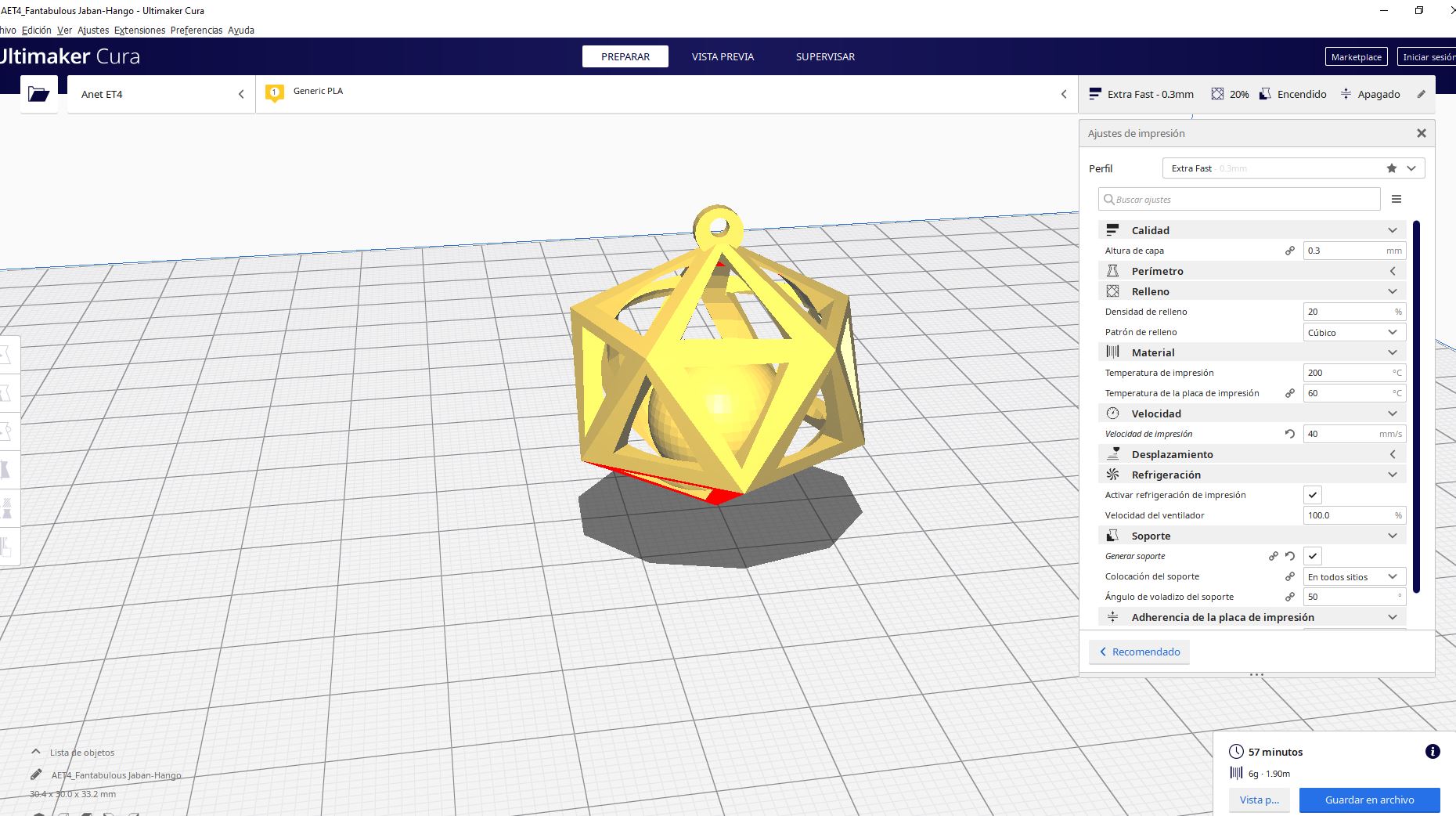
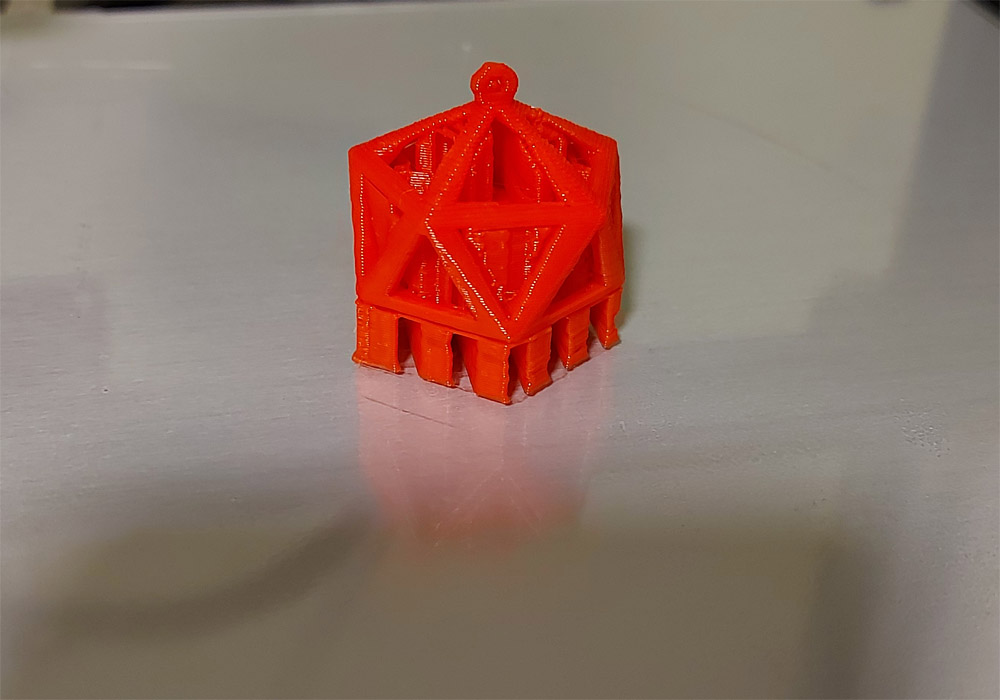
    In this way we will start the design of a figure that in principle, due to its shape, could not be built with subtractive techniques as with a cnc


    For this we will use a cube and two opposing pyramids, then we will hollow out the piece by inserting hollow triangles and we will group the pieces until we achieve a result as in the following image


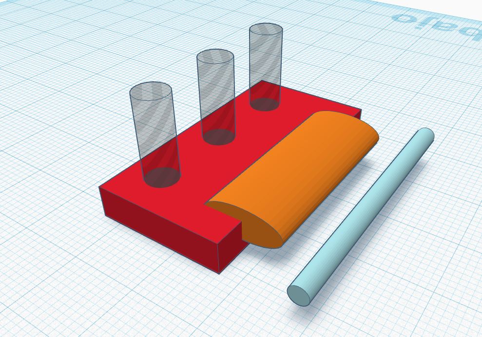
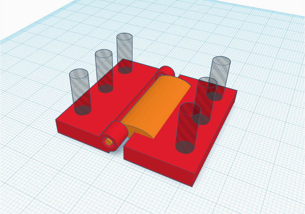
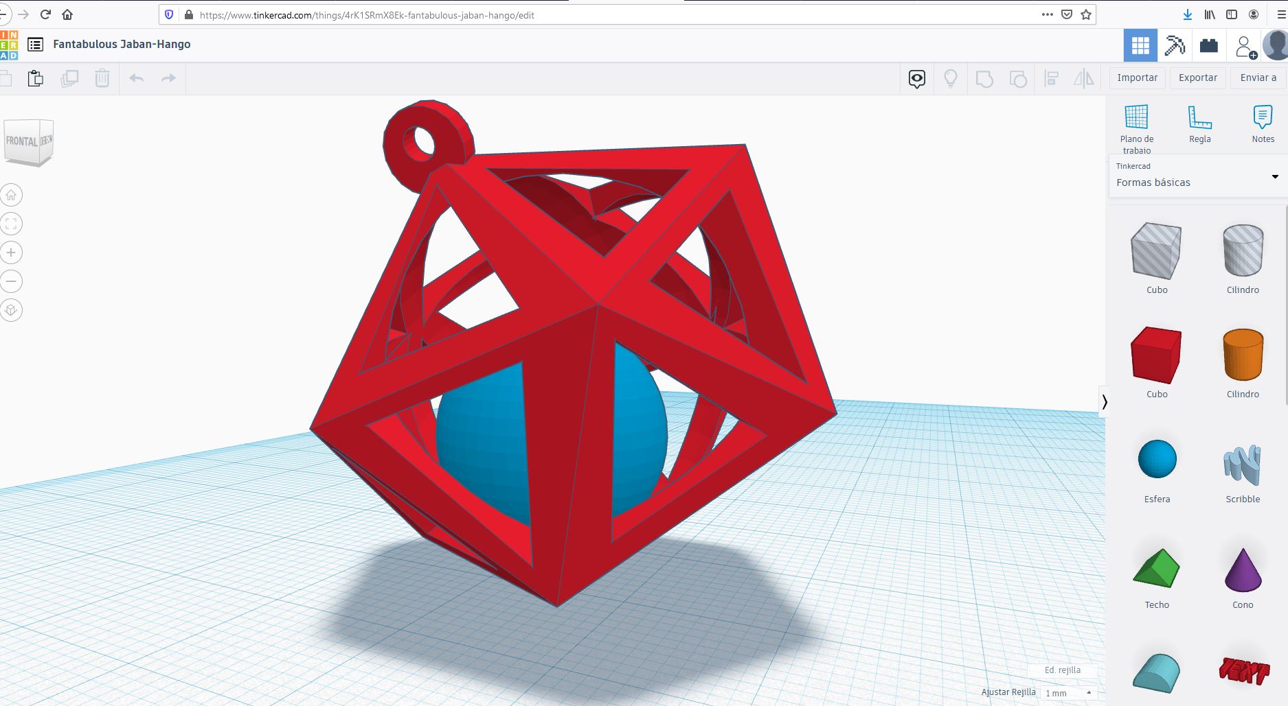
    Finally, we will place a sphere inside the figure, this is achieved by changing the height and position parameters, this sphere should not touch the outer figure, for at the time of printing, it is created with supports that later we must break to free the sphere.


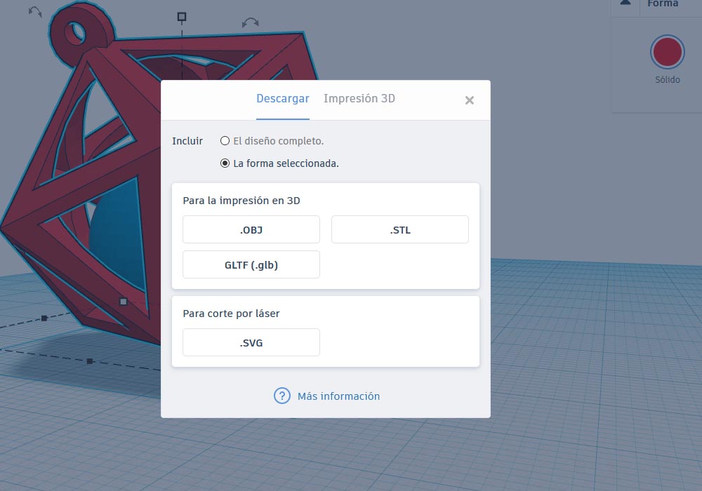
    TinkerCad allows us to export our figures to be printed on our 3D printer so we can obtain OBJ, STL and GLFT formats and even SVG format for laser cutting


    file download

    Pendant

    Pendant file in Fusion 360


    Second try


    To better understand the mechanics of the exercise, I decided to design a hinge that is printed on a single body but can be articulated.

    For the design of my door hinge, I chose to use THINKERCAD this is an Autodesk online program, it is very simple and intuitive, but at the same time very powerful and with a number of tools it allows us to design very interesting pieces, with some patience and imagination you can achieve very powerful jobs, then I show the steps that I did for my design


    We begin with a basic shape, in this case a cube, to which we vary its dimensions until it takes the shape we are looking for.


    then we add a cylinder and rotate it until it is parallel to the previous figure as we can see in the following figures


    With a few geometric shapes we can go forming our door hinge, some imagination and using the deformation tools and then we are shaping it


    In Tinkercad it is very difficult to locate the pieces because they make jumps in the grid, and this cannot be configured, we would not have control in the case of needing tolerances in our pieces, tinkerCad is a very friendly tool and allows us to create very complex shapes, but if accuracy and tolerance management or design parameterization is necessary, it would be better to use other tools such as solidworks


    Now with everything in place we can print our piece and see how it works


    As can be seen in the image, the parameters used for the manufacture of the door hinge were 0.3mm layer height, 20% fill density, 50 printing speed and with support in all places.


    When observing the final result of the two pieces, and after going through the assignment of molding and casting, I think that the pendant is the first figure manufactured, perhaps it can be manufactured by the subtractive method, on the other hand when looking at the door hinge especially in the part of the union of the two parts, I think that the additive method would be the only way to make it, TinkerCad allows us to save our models in a fusion 360 file


    file download

    door hinge

    door hinge Fusion360 file

    TinkerCad Hinge files

    TinkerCad Pendant files

    3D Scanning:


    As director of the research projects of the computing career. I have had an approach to computer vision projects, as well as to the augmented reality project, so it is not strange for me to use 3d scanners such as Microsoft's kinetic, or the capture of three-dimensional models, through cameras or multiple images of an object


  • Scanning with Skanect and xbox360 Kinect
  • The first thing was to start from a simple design that allows more pieces to fit together to form larger structures.
    To capture real elements and pass them to a 3D model, we will use the software Skanect, and xbox360 Kinect to be able to capture a model through the sensors of the kinetics


    At the end of this segment we can find a YouTube turial video where they explain step by step its use and configuration


    Important things at the time of scanning, is to maintain a constant distance and make fluid and constant movements, the truth is that Skanect has an interface that changes color and tells us when the scanning parameters are correct, we can see in the image that the scanned model remains green if we are capturing the model correctly


    We can give several turns around the model until we observe that the entire model turns green, we must put special emphasis on the upper and lower parts in this way we will avoid that our final model has too many holes


    We can see a first attempt, but the truth is not with too much detail, so we will vary some configurations to see if we can scan a model with more details


    finally we get a model with more details, and we are going to print it on a larger scale


    file download

    Girl 1


    "1 hour printing" Vs "6 hours printing"


    file download

    Girl 2


    Which 3d printer I use

    For this week's assignment, I used an anet et4 printer which I improve, changing the bowden structure for a direct structure, the reason for this improvement. be able to print with tpu, I have this printer at home for tests, and has the following characteristics:

    Model: Anet ET4.

    Red color.

    Power supply: 220V AC 240W.

    Structure: sheet metal frame.

    Print technology: FDM.

    Extruder Quantity: 1.

    Print size: 220 * 220 * 250mm.

    Printing resolution: ± 0.1 mm.


    Useful video of the process


  • Scanning with Meshroom
  • There are other techniques to be able to capture an object as a 3d shape, one of these techniques is through a series of several photographs (about 150 photos), to through an algorithm, get the computer to understand the depth of the image, and that the computer can reconstruct an object.

    The important thing here is to take enough photographs, especially of details, so that the computer can interpret the object as a three-dimensional model.

    Of course, the results will not be as impressive as those obtained with a scanner dedicated to this work, but it is still an interesting way to capture an object, I believe that with the improvement of algorithms and the work carried out in the field of computer vision this task will be much better in the future


    It is advisable to right click on folder number five and calculate, this to prevent the computer from freezing, after this process you can repeat the process in folder 12


    Dino STL file


    Useful video of the process


    General Conclusion:


  • A good filament and correct parameters will help us when printing our pieces, but to achieve perfection or something close to it, we must first know our printer well, to know how far we can force the parameters at the time of obtaining quality Vs printing time


  • For 3d scanning, the key is patience and treating the scanner like a brush, giving firm, smooth and constant brushstrokes will help us achieve better scans.


  • And what about 3d modeling through photographs, well, arm yourself with patience and take many, many photos


  • Return