INTRODUCTION
We realized that our lab needed a machine to drill electronic plates, a job that had been
done manually with a dremel lately. As a starting point we used a machine that our
tutor bought months ago but had not been used.
The machine seems to be working fine but we'll adapt it to do what we want.
THE PROCESS
PHASE I - ENABLE THE MACHINE
We took advantage of our abilities and divided the work that needed to be done.
Camilo and Ismael are in charge of the mechanical and electronic part, Jeffery in charge of the
software and Roberto and I in charge of the modeling and printing of the missing
parts for the assembly of the machine.
On our first meeting we verified that the machine works and we made a list of activities and responsibilities to meet the schedule.
The items to be done in this phase were:
- Check actual status and find out how it works
- Check what is missing for the machine to work
- Define and get the BOM
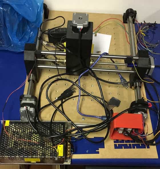
The axes of the machine move without problem and we have determined to use lasers so that the machine can identify the origin. We will use Bcnc to control it.
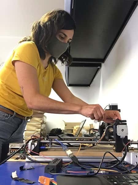
PHASE II - INTEGRATE THE SYSTEM & SOFTWARE
Time to get to work, these are the activities that we determine for this phase:
- Find out the 0,0,0 of the machine @ismael and camilo
- Electronic board modifications @ismael and camilo
- Design and 3d print dremel holder, cable clips, end stops supports and sights for lasers @daniela
- Software and raspberry @jeffery
- Design and 3d print power case, emergency stop and arduino case @roberto
DESIGN AND PRINT @daniela
I was in charge of the design and printing of some pieces. I started with the dremel support,
taking as a reference the support that was built into the original machine to take advantage
of some of the parts. I replicated the measurements and adapted them to the dremel that we
have in the laboratory and that will be used to make the holes.
I looked for an existing model on thingiverse to see how other people have faced this same situation.
You can find this model here:
Dremmel3000 mount.
Then mixed this design with the existing piece in order to maintain the location of the support bolts.
This was the first result:

For the following modifications, I made a conical support at the base to suit the dremmel, lengthened the
height to provide more support, an intermediate clearance for ventilation and a lock on the top.
Printed this model, but during the process the power went out and only had half of the piece.
This was helpful because it allowed me to make some measurement modifications to the model.
I realized that the temperature with which I was printing was too high and this was generating a
deformation in the overall dimensions of the piece, making it longer, affecting specially the bolts
perforations making them barely reach to enter the support.
The conical base fitted perfectly. The diameter of the top bracket of the dremel was insufficient
and I noticed that it is not cylindrical but oval. In general I added more tolerance for the pieces.
The complete printing process of this piece takes around 11 hours so I decided to focus on the other pieces during
our day at the lab to be more efficient with the time we had to work together. We needed to
fasten the limit switches to the shafts and for this I looked for some inspiration on thingiverse.
These are some of the models I based mine on:
Parametric pipe clamp.
Pipe clamp snap on one screw.
PVC pipe clamp.
The first one I printed was too tight, and when we tried it, it broke a bit.
I modified the diameter of the shaft, added the limit switch on one side to make a single integrated piece.
It fit perfect for what we needed.
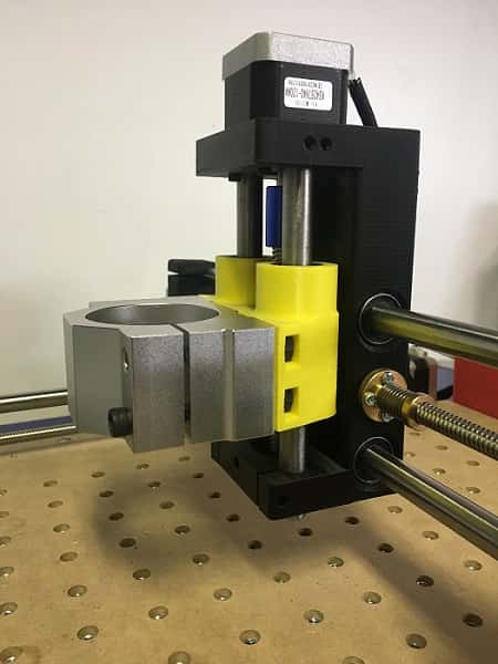
Two of this supports needed to hold the laser, I adapted it for both axes.
The next piece is designed to hold the phototransistor that responds by matching the laser.
Printed once again the dremel support, this is the result:
The dremel still doesn't fit, once more increased the diameter measures, reduced the total depth of the piece,
increased the diameter for the bolts and this is the result:
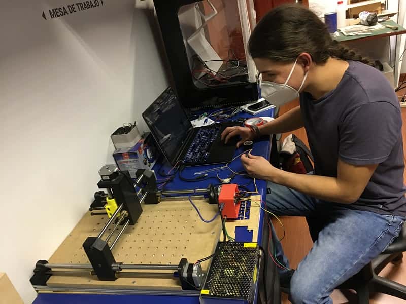
PHASE III - SOFTWARE
For this phase we need to integrate the code, try the machine connected with the bCNC, the use of the rasperry pi.
You can find more details about his phase in ou gruop page avaliable in the following link:
More information.
PHASE IV - TESTING
So far our machine is working 75%, we still have to work on some details but you can see it working
here.
FINAL THOUGHTS ABOUT THIS WEEK
This has been an interesting week working together, I think we make a pretty complete and complementary group,
which made easier for us to work toward our goals. We took advantage of our capabilities developing what we are
better at. It is interesting to learn by making mistakes, suggesting ideas for others, using the machines at the lab,
despite our local restrictions and situations around covid.