3D SCANNING AND PRINTING
3D scanning is the process of analyzing a real-world object or environment to
collect data on its shape and possibly its appearance like color. The collected
data can then be used to construct digital 3D models. It is useful for a wide
variety of applications, it's used extensively by the entertainment industry in
the production of movies and video games, including virtual reality, other common
applications can include augmented reality, motion capture, gesture recognition,
robotic mapping, industrial design, orthotics and prosthetics, reverse engineering
and prototyping, quality control/inspection and the digitization of cultural artifacts.
3D printing , or additive manufacturing, is the construction of a three-dimensional
object from a CAD model or a digital 3D model. The term "3D printing" can refer to
a variety of processes in which material is deposited, joined or solidified under
computer control to create a three-dimensional object, with material being added
together (such as plastics, liquids or powder grains being fused together),
typically layer by layer.
CHECK LIST
Group assignment
- Test the design rules for your printer(s)
- Document your work and explain what are the limits
of your printer(s)
Individual assignments
- Design and 3D print an object (small, few cm3, limited by printer time)
that could not be easily made subtractively
- 3D scan an object, try to prepare it for printing (and optionally print it)
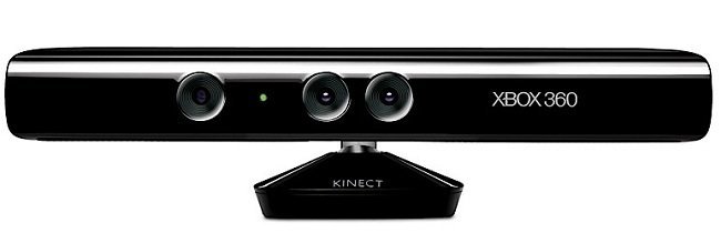
KINECT AND SKANECT
Xbox Kinect, employs a combination of cameras and an IR rangefinder.
Skanect has a scan workflow built into the software that’s easy and
intuitive. You just follow along, setting your scan size and scanning
the object. It has good post-processing tools that will help you fix
areas that didn’t scan correctly, including stray points, which
almost every scan has. The software also offers helpful feedback
as you scan, indicating which points the software is able to read
and those it’s having trouble with.
WORKFLOW
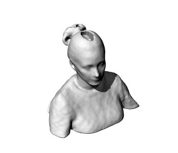
I found it really interesting and fun to scan ourselves for this exercise.
- Sit down facing backwards. This helps reduce mistakes during the scan specially
on details on the nose.
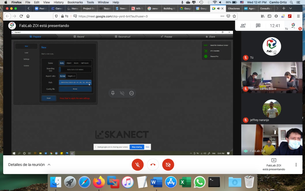
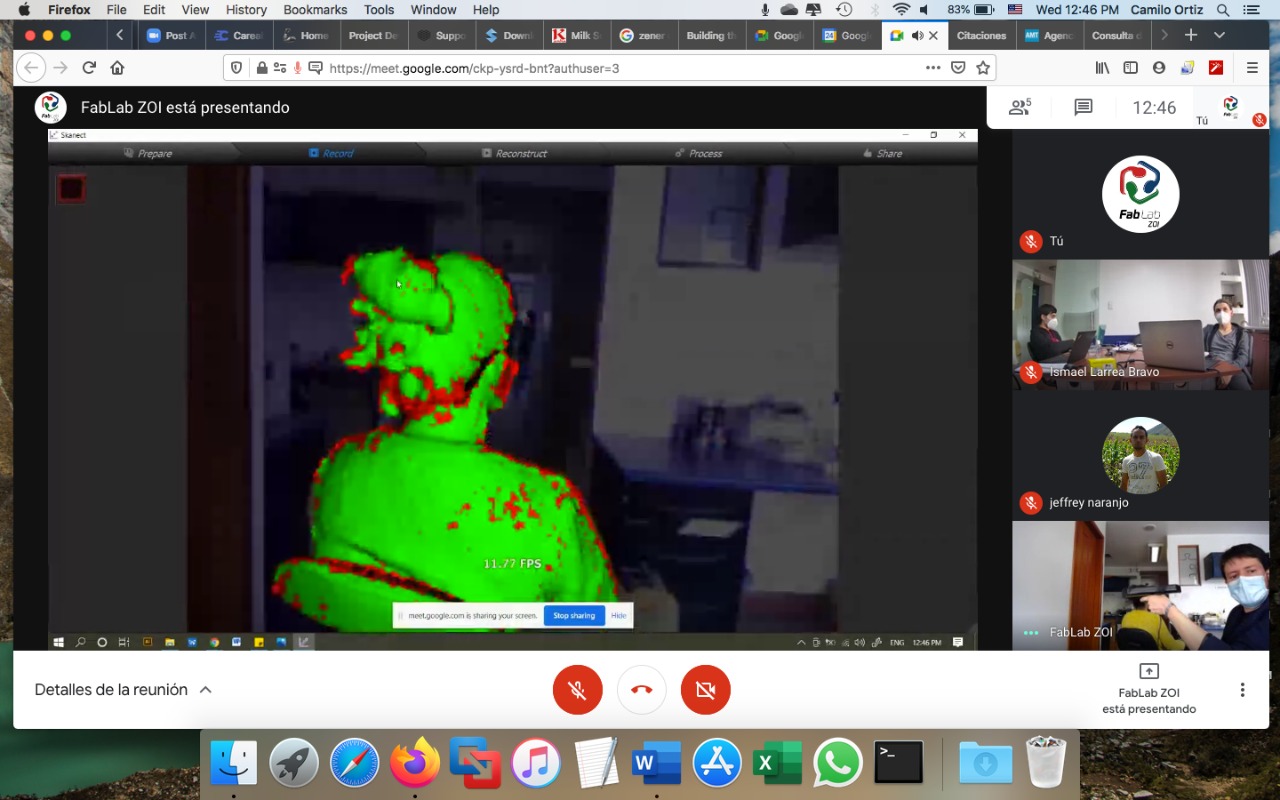
- On skanect (the sofware we used) press "Prepare", here you will set up some details like:
Scene (in this case body), Bounding box to delimit the scanning volume (1x1x1 meters),
Aspect radio Normal, Path to select the folder where you want to work and
Config file None. Then press Record.
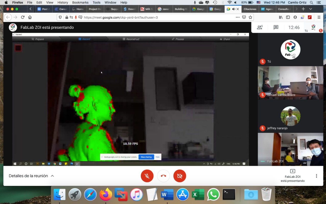
- Move the scanner around the subjet to make sure the area, colors will be shown on
the screen. Make sure only the subject is being recognized (not walls or other element around).
When you can see the subjet on green, and all the subjet is inside the box boundary, you are ready to start.
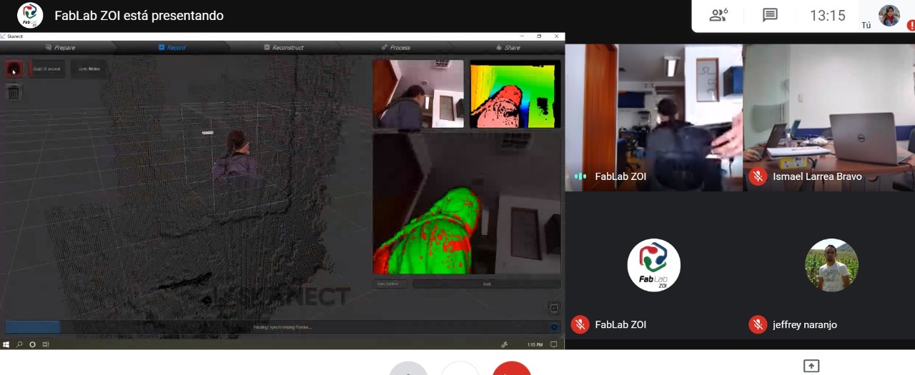
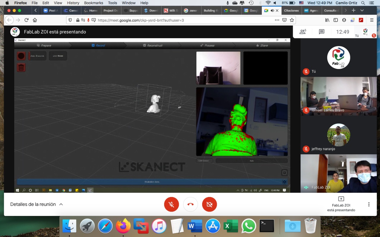
- The subject must rotate on its own axis (X / Y) 360 degrees slowly
- On Z axis another person has to move the kinetic scanner to record this data.
- Make sure to cover the top of the head and the lower part of the chin.
-
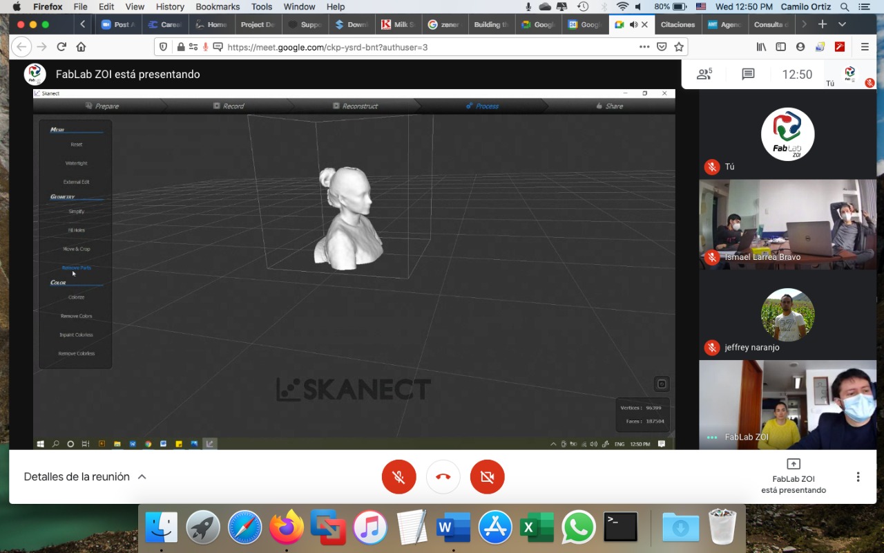
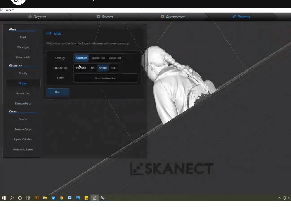
- When the model has being recorded go to Process to clean some final details
- On Geometry: Fill holes: Strategy: watertight, Smoothing: Medium, the RUN. This
step will fill the holes on the model where needed.
- Save file as .obj, choose the folder where you want to save it.
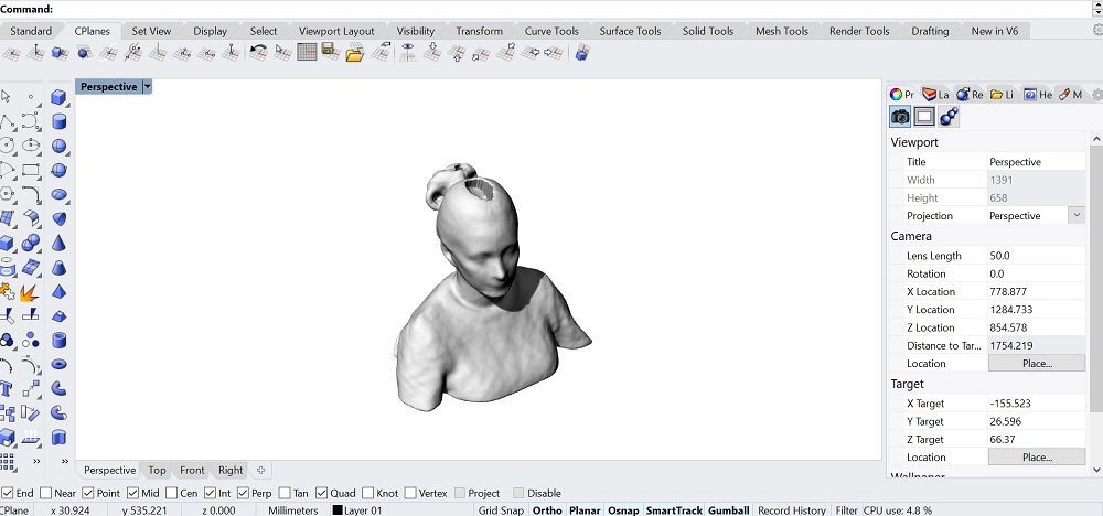
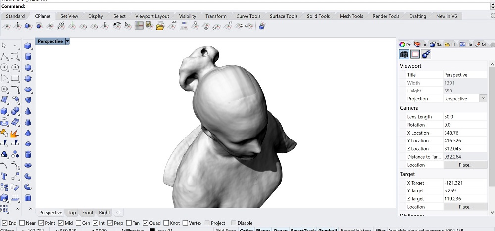
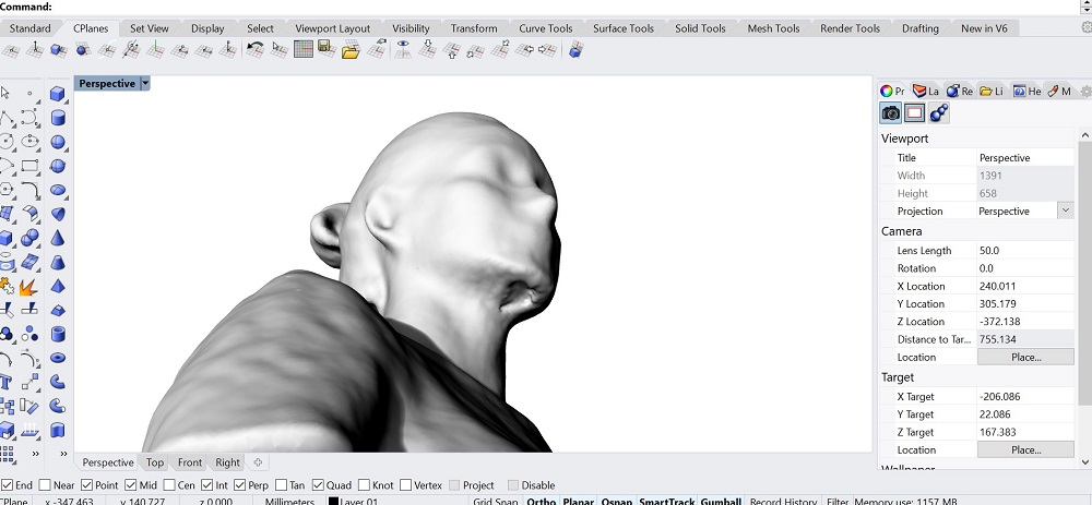
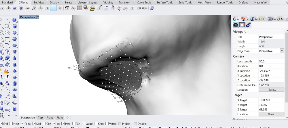
PREPARE THIS FILE TO PRINT
With the .obj file from skanect, I opened Rhino to correct some details on the model
and export it for 3d printing as a .stl file. There were two missing parts that I
filled, one on the top of the head using surface from network of curves and for the
part missing below the chin I drew a curve around the hole and a patch, with this surface
I was able to move points and adapt it.
files
Scanned
3d corrections - rhino
fdm
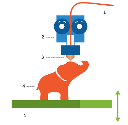
Fused filament fabrication (FFF), also known under the trademarked
fused deposition modeling (FDM), sometimes also called filament freeform fabrication,
is a 3D printing process that uses a continuous filament of a thermoplastic material.
Filament is fed from a large spool through a moving, heated printer extruder head,
and is deposited on the growing work. The print head is moved under computer control
to define the printed shape, usually in two dimensions to deposit one
horizontal plane, or layer, at a time and then moved vertically
by a small amount to begin a new layer. The speed of the extruder head may also be controlled
to stop and start deposition and form an interrupted plane without stringing or
dribbling between sections.
materials
For our group and individual assignments we used PAL (Polylactic Acid)
which is a polymer plastic made from biological materials such
as cornstarch or sugarcane. It is similar to the material used
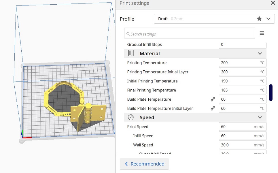
in biodegradable plastic packaging. It melts between 180 - 200
egrees C, depending on other materials added to it for color and
texture.
PLA is tough and resilient but not as heat tolerant as ABS.
It begins to deform at temperatures higher than 60 degrees C.
It is also not water or chemical resistant. There is a slight
smell when it is heated but no toxic odors or vapors.
More information about other materials can be found
Here.
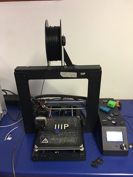
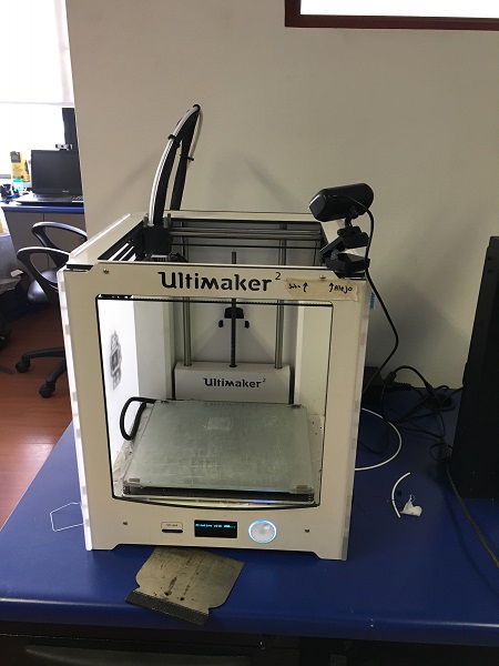
printers
There are two 3D printers at the Lab, the cura ultimaker and the prusa i3.
- prusa build volume: 250 x 210 x 210 mm
- ultimaker build volume: 223 x 220 x 205 mm
The software used for both is Ultimaker Cura 4.8.0
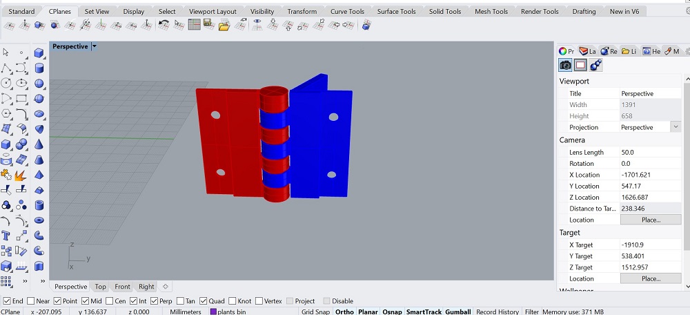
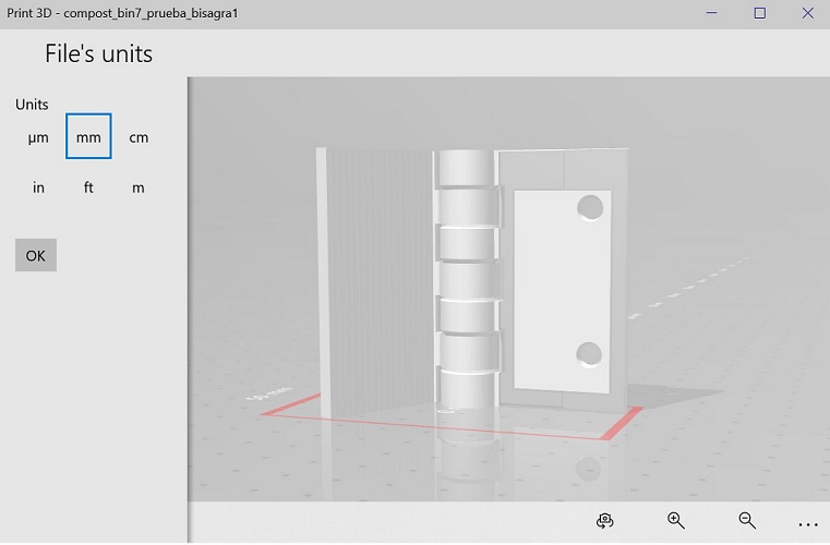
3D DESIGN
For my final project I'm planning to use a hinge for the compost bin
case to open. I designed one based on a wallet model I downloaded from
thingiverse, then I edited it to fit my project. For this exercise I
selected one section of the hinge because the final es too long and my
main purpose is to test that the design works.
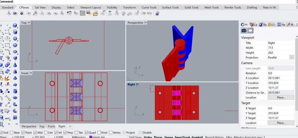
Once the model is ok, export it as .stl to 3D print later.
It is important to remember that the 3D print also has a clearance. For this
exercise I used a 1mm offset for the hinge to have the necessary mobility.
The recommended kerf can go from 0.8 - 1.0mm.
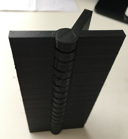
In a previous test I forgot to leave this tolerance in all the gears, this
was the result, I couldn't open it. For this exercise this technology is a great way to
achieve the expected result as it can not be done subtractively because there is an interior
gap that allows both pieces to move and interact with eachother. The desing was done to keep
45 angles inside and no need of supports, thing that can not be achieved in a different way.
Files
3D wallet model - thingiverse.
3D wallet model - stl.
Rhino model.
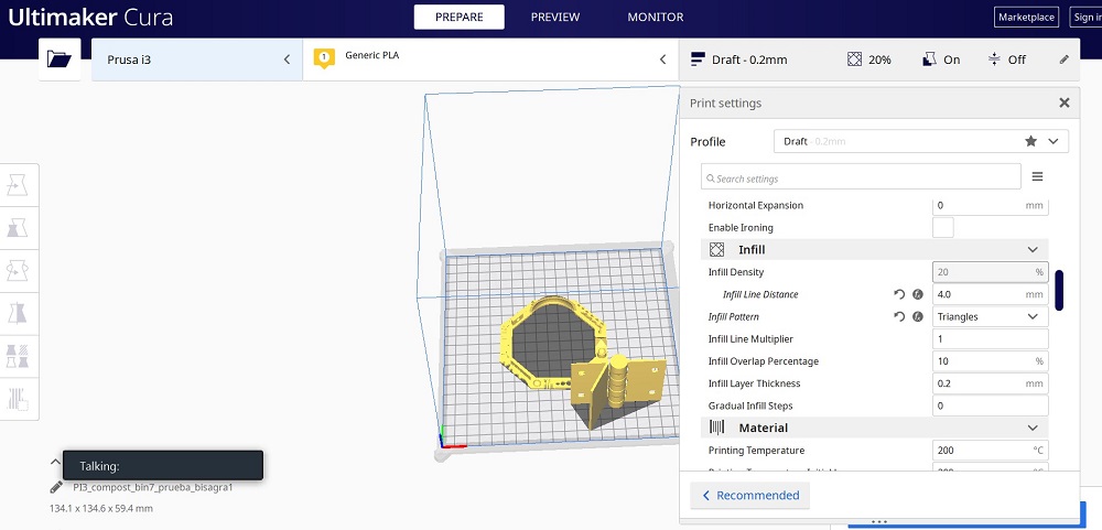
WORKFLOW
- Open ultimaker cura software
- I open a file the was given to my at the lab that has most of the configurations ready
- Drag the file to print and errase the previous one
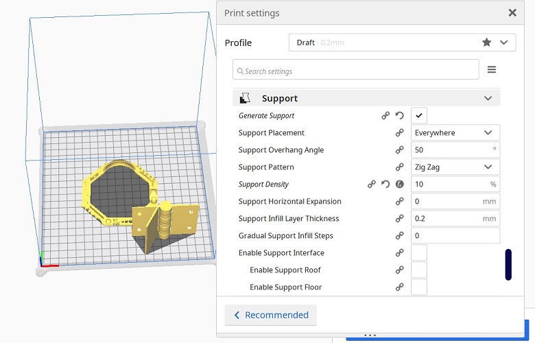
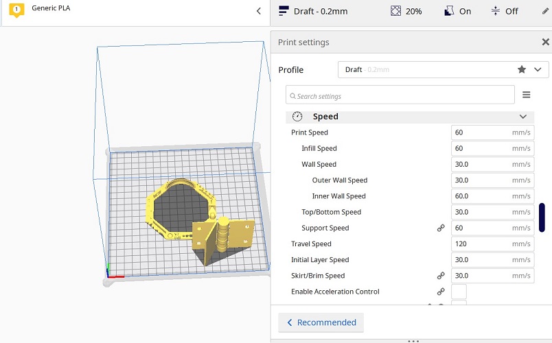
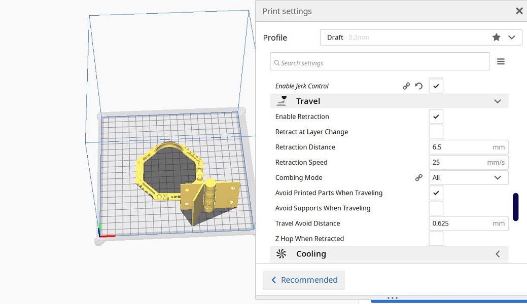
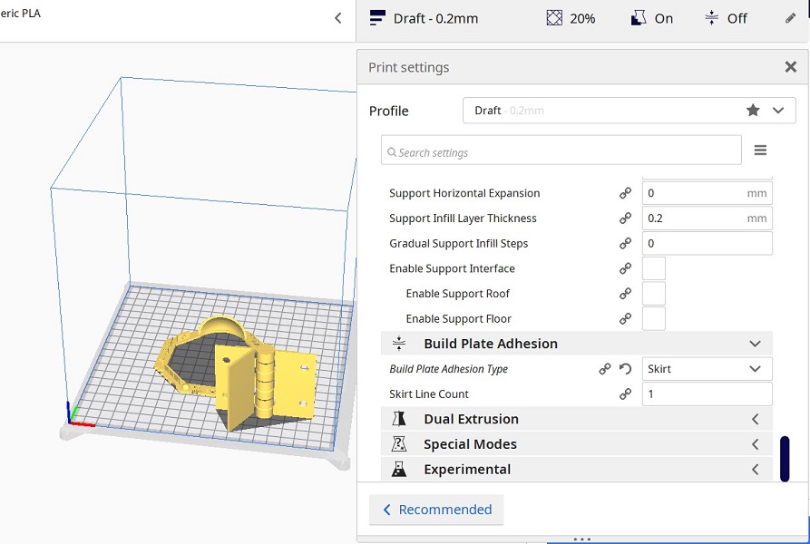
- Set the parameters for: infill, material, speed, support, built plat adhesion
- These are the parameters I used for this exercise
-
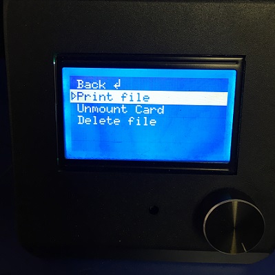
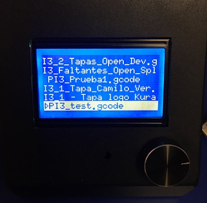
- Once all the parameters are ready I saved it to a SD card
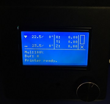
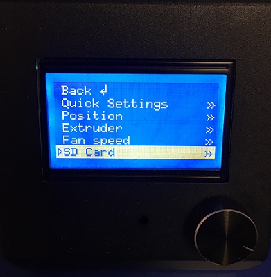
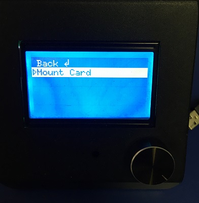
- Insert the SD Card on the printer
- Follow the next steps. The time planned was around 3 hours
DESIGN PRINCIPLES
Ismael found this interesting link with the design principles. Very important
to understand and keep them in mind.
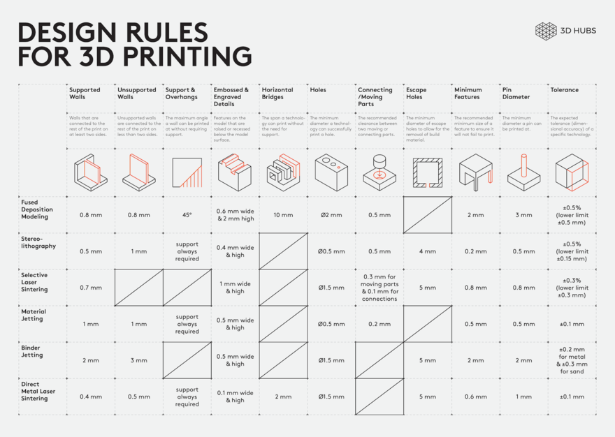
Design principles .
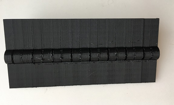
FINAL RESULT
The final result wasn't as I expected, there are a couple of things I'll have on mind for my next 3D print exercise.
Diego shared this link "Visual ultimaker troubleshooting guide, very usefull for this kind of situations.
Click here .
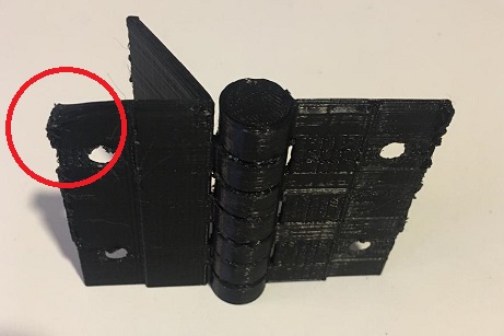
- The final part of the hinge is bended, kind of melting. The layers on the bottom came out right but many problems on top.
- According to this web site it might be cause of the temperature used, the recommendation is to experiment with lower temperatures.
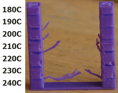
- This image shows clearly how lowering the temperature has a very positive effect on the
amount of stringing. As always when lowering temperature you must also make sure that you
are printing slowly enough to prevent under extrusion. Note that the temperatures shown in
image is for PLA, for other materials you may not be able to go this low. Or conversely,
you may be able to go even lower
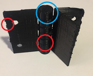
- The blue circle show the only 100% functional part of the hinge, the internal supports are right,
bridges were easy to remove and it moves.
- Red circle on the left, again, kind of melting and has a lot of residues.
- The reason overhangs come out uglier than a straight wall is simply because new layers are
not properly supported by the preceding layer. Rather than fully resting and being anchored
in place by the previous layer the new layers are partially printed into mid air and tend to
sag down slightly or curl up. Sometimes these issues accumulate making each layer worse than
the last. Curling around corners when using thin layers seems to be especially problematic.
Dealing with overhangs is tricky, there are many variables that will affect how well
or badly they will be printed. Temperature, print speed, amount of overhang, layer height,
material, and cooling all play a part in how an overhang will print.
- I'll reconsider my design with this recommendatiosn
- Red circle on the bottom, internal unions are not moving, for this I will reconsider the
amouth of overhang angle support (in this case was 50) and the support density (10, shoud try less).
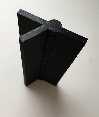
After cleaning the excesses in the joints, the hinge works, this is the final result.
SOME THOUGHTS ABOUT THIS TECHNOLOGY
Thinking beyond, I find it very interesting the different points of view
that may exist in the use of this technology. From its applications in
medicine, visualization, to gastronomy or industry. It can be a very
effective solution but you still face complications like time vs money
in relation or other types of manufacturing. Anyway, I think that 3D
printers have become tools that allow us to find customized solutions at
our fingertips and modified to solve our specific needs, solutions that
otherwise could not be bought anywhere.
It is still a field that can provide wonderful solutions, we will see how
it continues to develop.
From my experience this week it has been interesting to try new things with 3D printing, the results were not as expected but
it was interesting to analyze all the possible situations that caused these results and understand how they can be solved.
