Week
Eight
Embedded Programming
Group Project
This weeks group assignment was to compare the preformance and developtment workflows for other architechtures. We did this by creating a google spreadsheet for information with all of the microcontrollers that we had on hand.

For each of the boards I worked to run blink on it. Blink is a built in example with arduino that just turns on the built in LED in any particular board. This worked excellent for the knock-off arduino that we had naturally because it is based off of arduino hardware which synched up nicely. For most of the boards that we have like the Teensy 4.0 it was just a matter of downloading the right software off the internet so that arduino can sych up. However for some boards like the ATtiny1616 we programmed it didn't have a built in LED so we had to chamge the code so that it would actually power an LED that is attached.
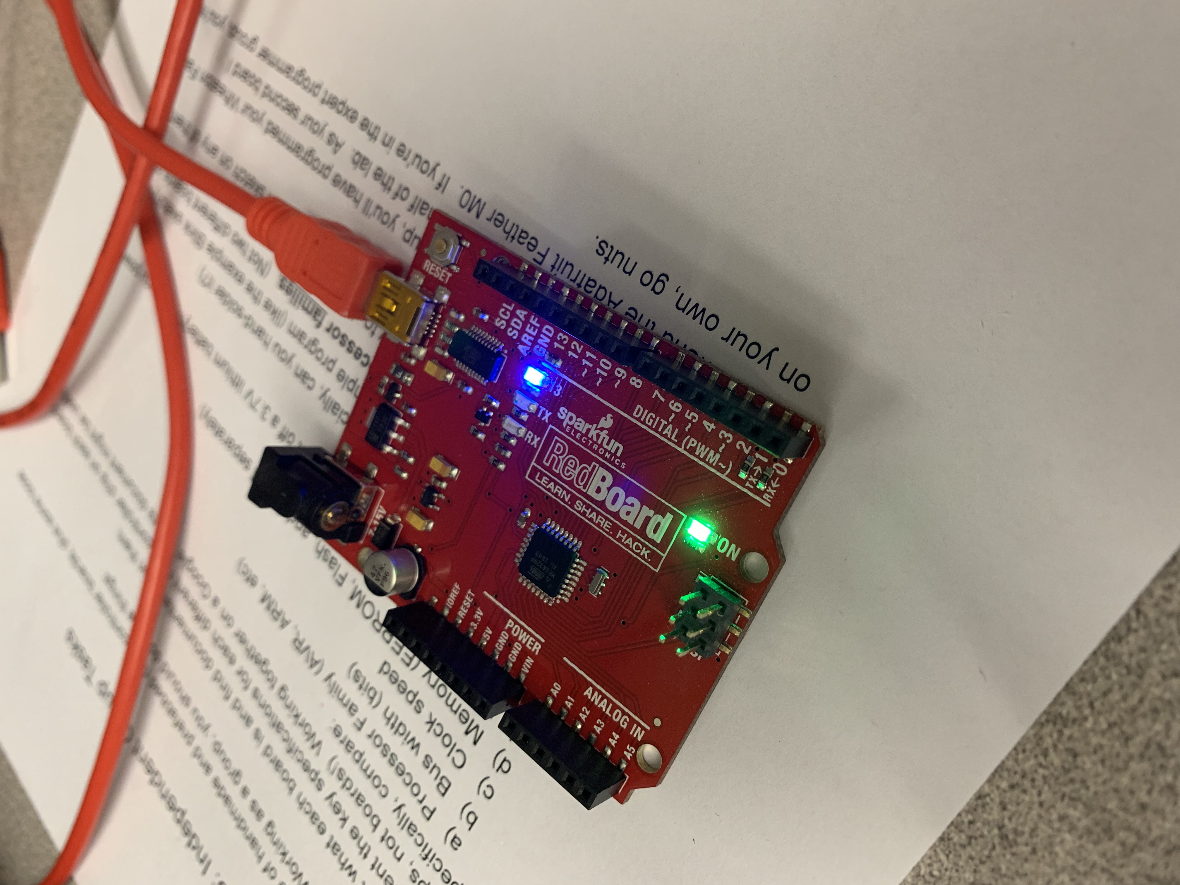
So in our work in coding the different boards we found that the actual part of coding the board wasn't to different. It was mostly an excerise in going to the manufacture's website, and reading the instructions. However we wanted to do a test to actually see the different clockspeeds of boards.
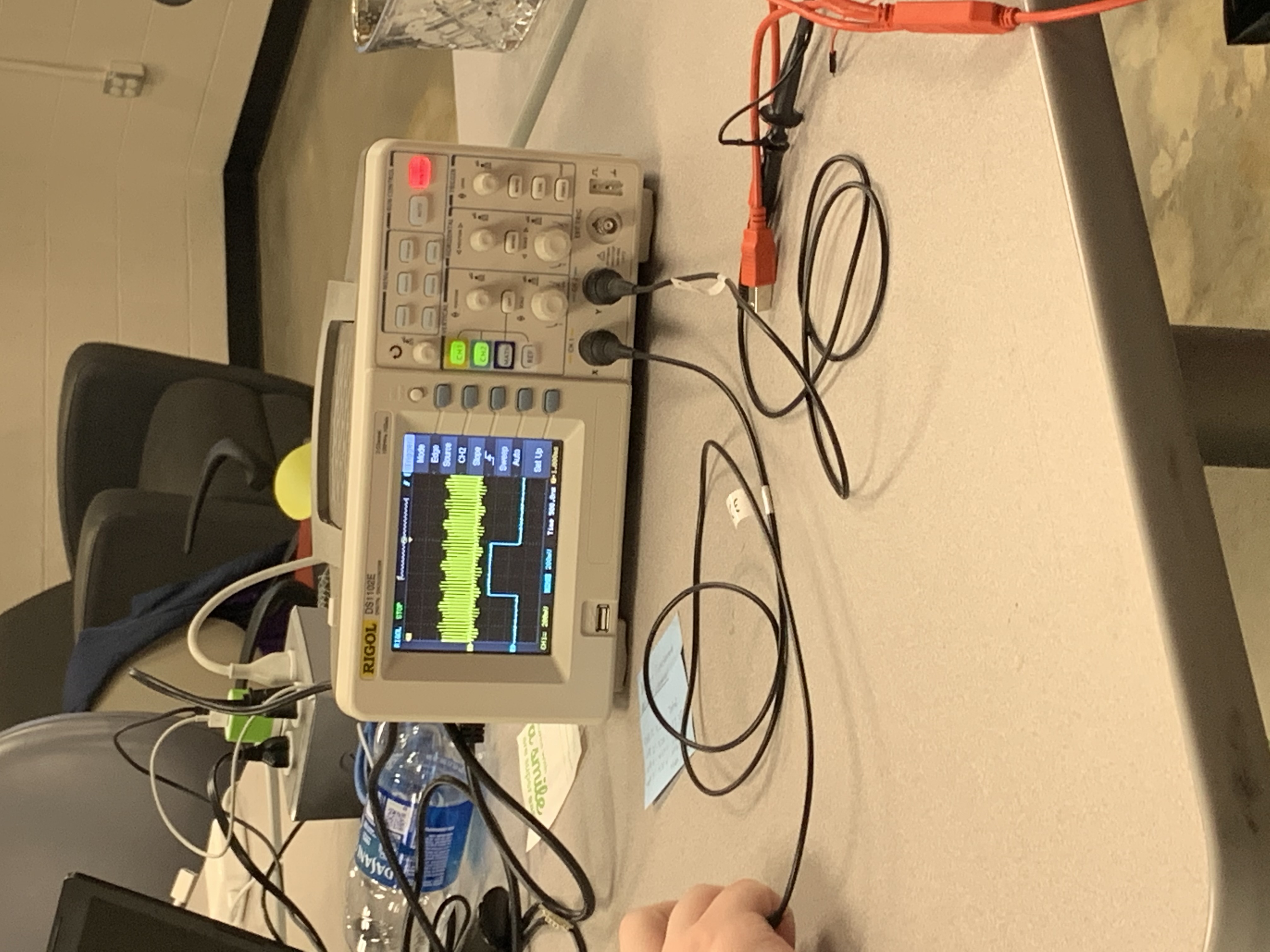
The way that we did this was setting a blink script without a delay, and then getting an osscilloscope. With the osscilloscope hooked up to the input part of the board we could actually see the signals the computer sent in. In doing this we could see that there were massive difference in the clock speeds if a PJRC Teenst against and Arduino. This when turing on an LED isn't very important. However if you are moving large files then you would want the faster board for sure.
Individual Assignment
Microcontroller Datasheet
The microcontroller that we are using in our lab is the ATtiny1616 so that is the data sheet that I read. In reading it I feel like I learned two important sets of things. One is the general specifications of the board.
| CPU | AVR® 8-bit |
| Clock Speed | 20 MHz |
| Flash Memory | 16 KB |
| SRAM | 2 KB |
| EEPROM | 256 bytes |
| Operating Voltage | 1.8V to 5.5V |
| Package style | 20-pin SOIC300 |
| I/O lines | 18 programmable pins (6 digital/12 analog) |
While the other excruciating important thing is the pinout diagram of the board. I likely would've had less problems with this project had I paid more attention to this diagram. It tells you what the proper labels are for all of the pins, as well as what each pin actually does.

Programming my Board
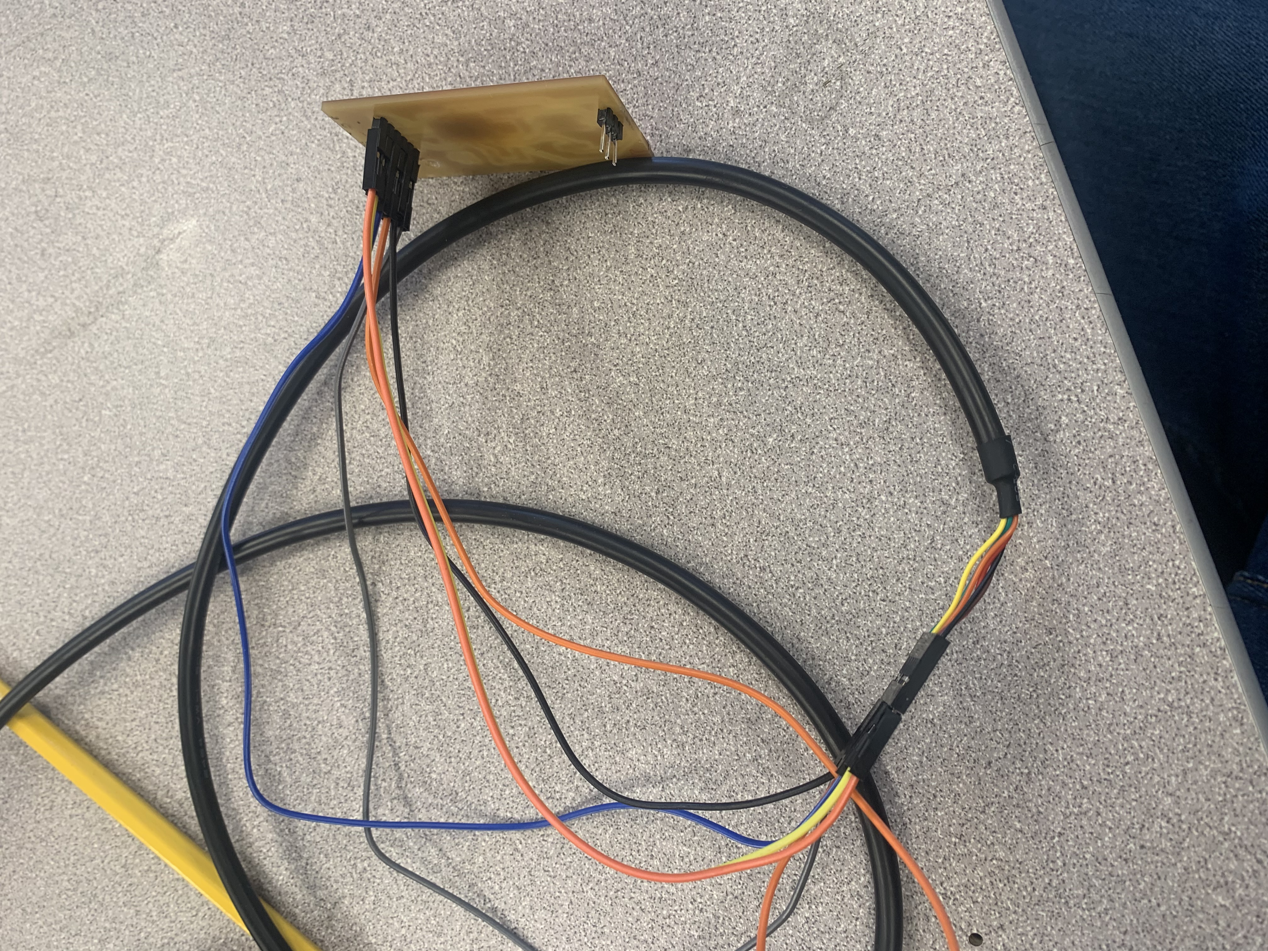
A couple of weeks ago I milled a board that I couldn't get working for the life of me. It turns out I mixed up my RX and TX pins, so to get my board to work I need to just run some cables to flip those, but then it works like a charm which is nice.
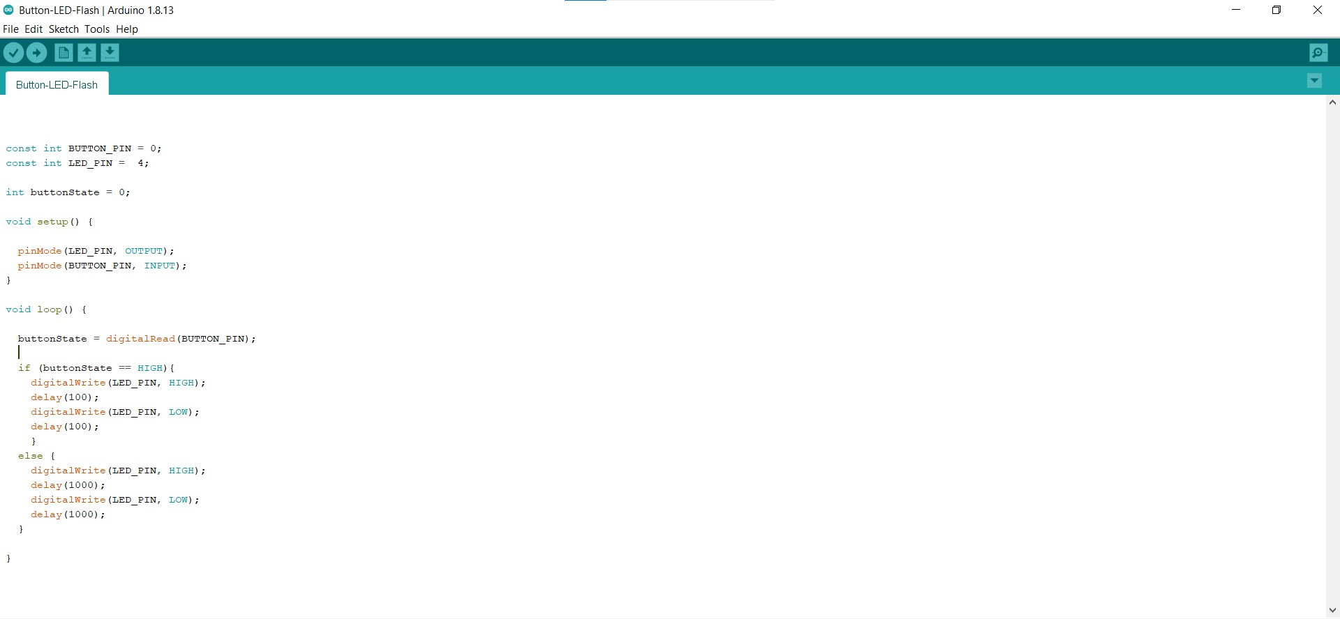
In regards to actually programming the board I wanted to have it set up so that the board would blink when plugged in and when you press the button the rate of flash would change to something faster. Ideally I would've liked it so that I could have the speed of flashing changable based off of button presses although I ran into problems with this because of the speed of the board and the delays caused it so I couldn't actually move from one setting to another instead I would shoot through like 5 settings. So I settled on my speed switching stategy.
IDEs and Languages
I'll put this out front I did not end up programming a board in anything but the arduino coding language which is really just dressed up c++. I did look into seeing how to do it in python because I do enjoy writing code in python. It is from what I gather entirely possible however to do it is an incredibly complicated process of turing a python file into an exectuatable and then getting them onto the micro controller.
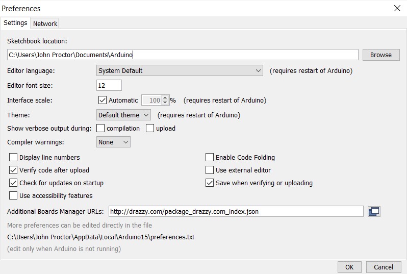
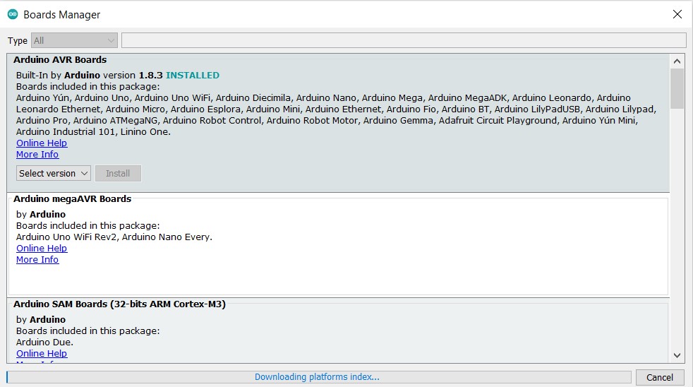
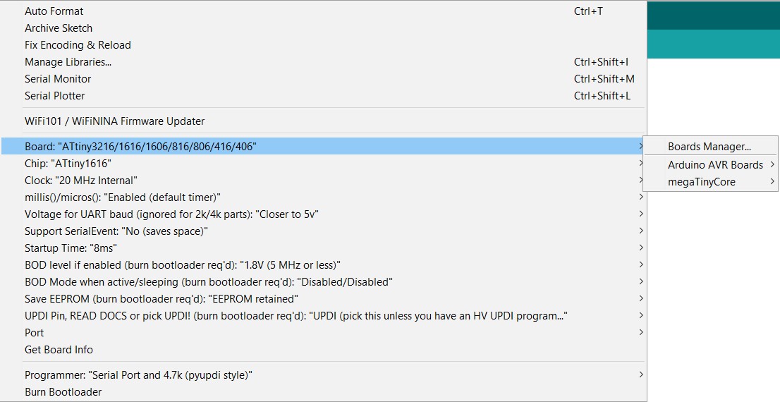
However I did use two different IDE's I used the arduino IDE which works very well once you download the drivers for your board. This process requires you to add another board manager and selecting the manager in your tools/board/board manager settings. Then going and selecting the board that you are using again in the tools/board settings.
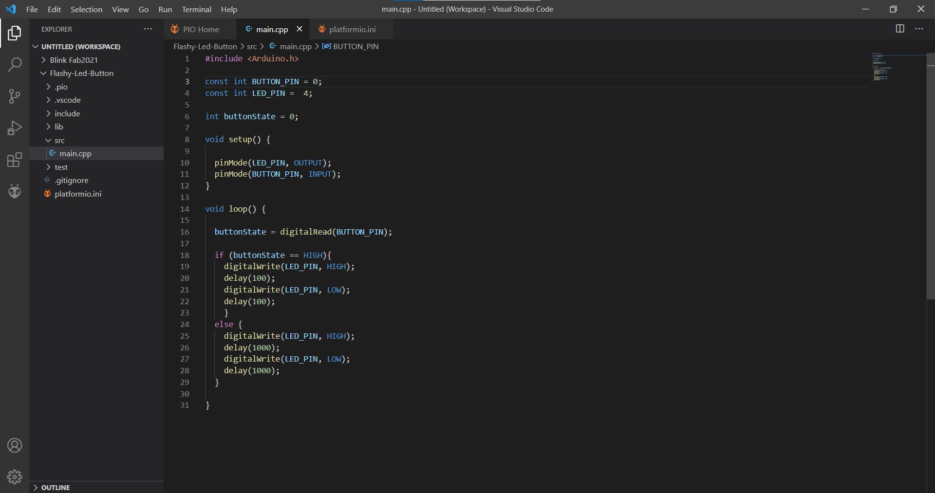
There isn't much to write when it comes to actually writing the code. It is an if statment in the loop. If the button pin is getting a reading then you run a blinking loop with a shorter delay then when the button pin is not getting a reading.
PlatformIO
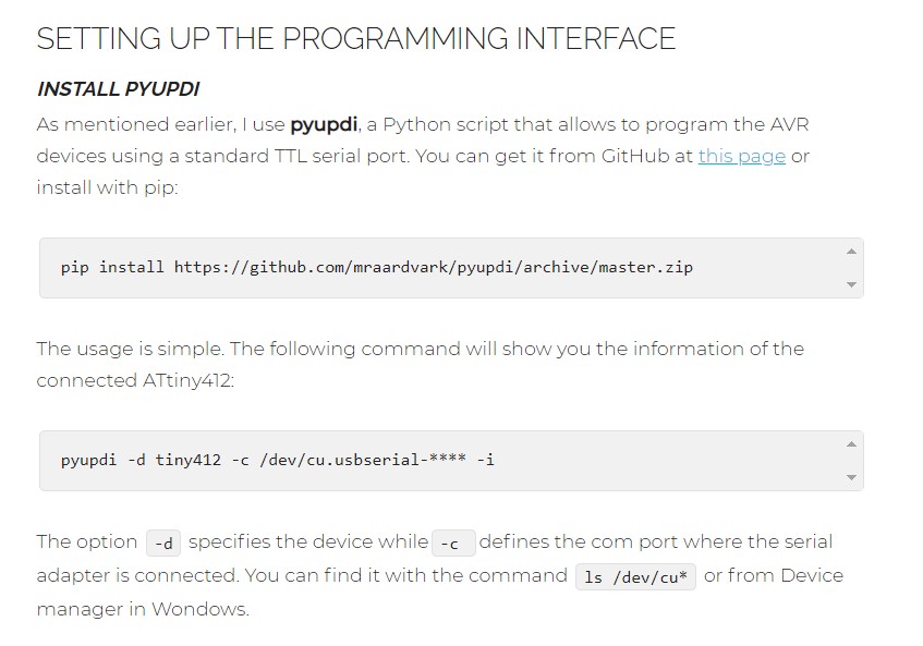
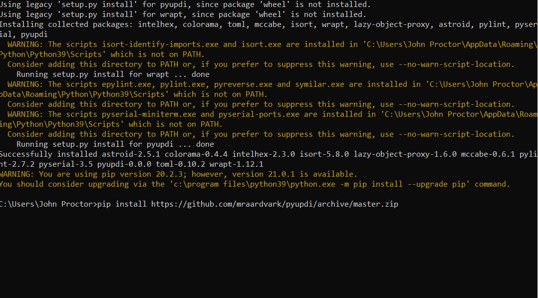
PlatformIO is an extension that you can add to VisualStudio Code. It is really neat becuase it comes with several hundred board built in so all that you need to do is select the one you are using, and the extension it's self will go and install the drivers. Then in a perfect world it should be just a matter of writing the code and uploading it like you do in the arduino IDE. However that is not how it works in practice. In practice you need to edit the .ini file to give it an upload command which is "pyupdi $UPLOAD_FLAGS -c $UPLOAD_PORT -e -f $SOURCE". Unfortunately computers do not naturally have pyupdi as a built in command, and to get it you must first have Python. So what you need to do is download python and make sure that you select to install pip. Pip from my understanding basically lets you do stuff in command line, although that could be completely out of line. Once you have pip installed you need to run "pip install https://github.com/mraardvark/pyupdi/archive/master.zip" in your command line. When you do that step it is important that you run your command prompt as administator that way pyupdi is added to the path, then you can just add the line I gave above in VS code. However if you don't like I did that isn't the end of the world you just need to add the file extension before pyupdi. Once that is all done then you should be able to just upload to your board no problem with the same code you wrote in arduino!
