3. Computer Controlled Cutting
This week was spent learning some of the intricacies in using a laser cutter.
Group Assignment
Working as a group, me and the other fab academy students here (Cristopher Proute and Terrence Carew) investigated the settings for our laser cutter (Epilog Helix-40W). Through multiple trials, we determined the power and speed setting that achieved a clean cut for the cardboard with a minimum of scorching along the cut lines. We also investigated the kerf of the cut using this material and these settings. Details here.
Individual assignment
This week’s activity was to design and cut an object in our laser cutter with interlocking parametric pieces, so that we can construct a 3 dimensional object out of the pieces. And to account for the kerf in our cut so that the pieces fit together tightly.
We used cardboard as our build material simply because it is cheap and easy to cut. Although cardboard is more flexible than other materials that we might use (plywood or acrylic sheets), the same principals apply.
However, using cardboard means that:
-
If we make the slot side of our joints slightly too small, our joint parts can still fit together. This simply because the insert section of the joint can compress slightly when going into the joint.
-
If we make the slot perfect, the joint can still end up slack. This again is because of the cardboard compressing slightly when being manipulated. This compression can affect both the width of the slot (expanding it) and insert (shrinking it), resulting in a looser fit than a harder material would give.
-
Orientation maters. The corrugation of the cardboard has a directional and varying component, the exact placement of the actual laser cuts relative to the corrugation can result in a changes in how much the material compresses. This is especially true for smaller components and joint.
Design:
-
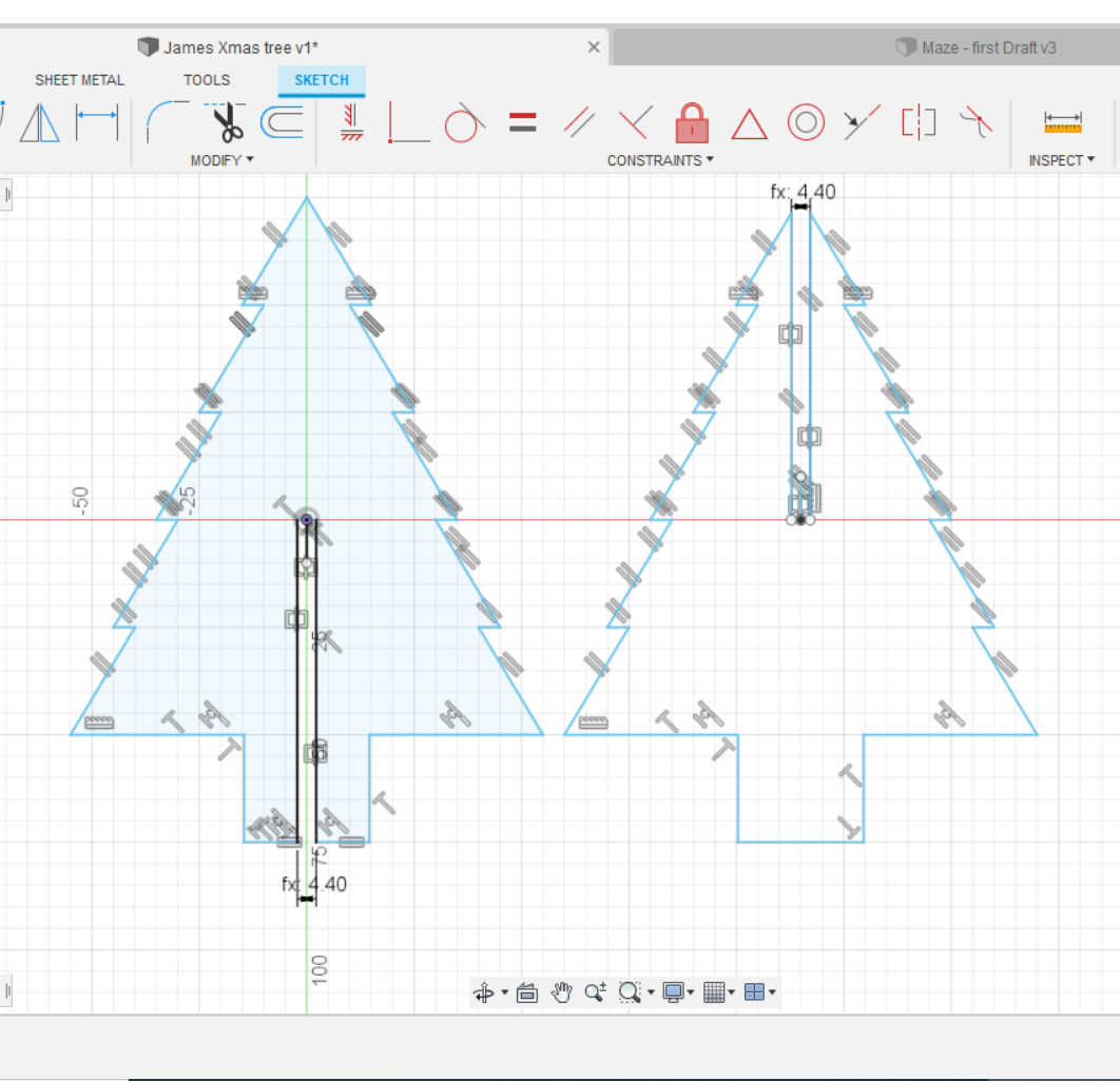
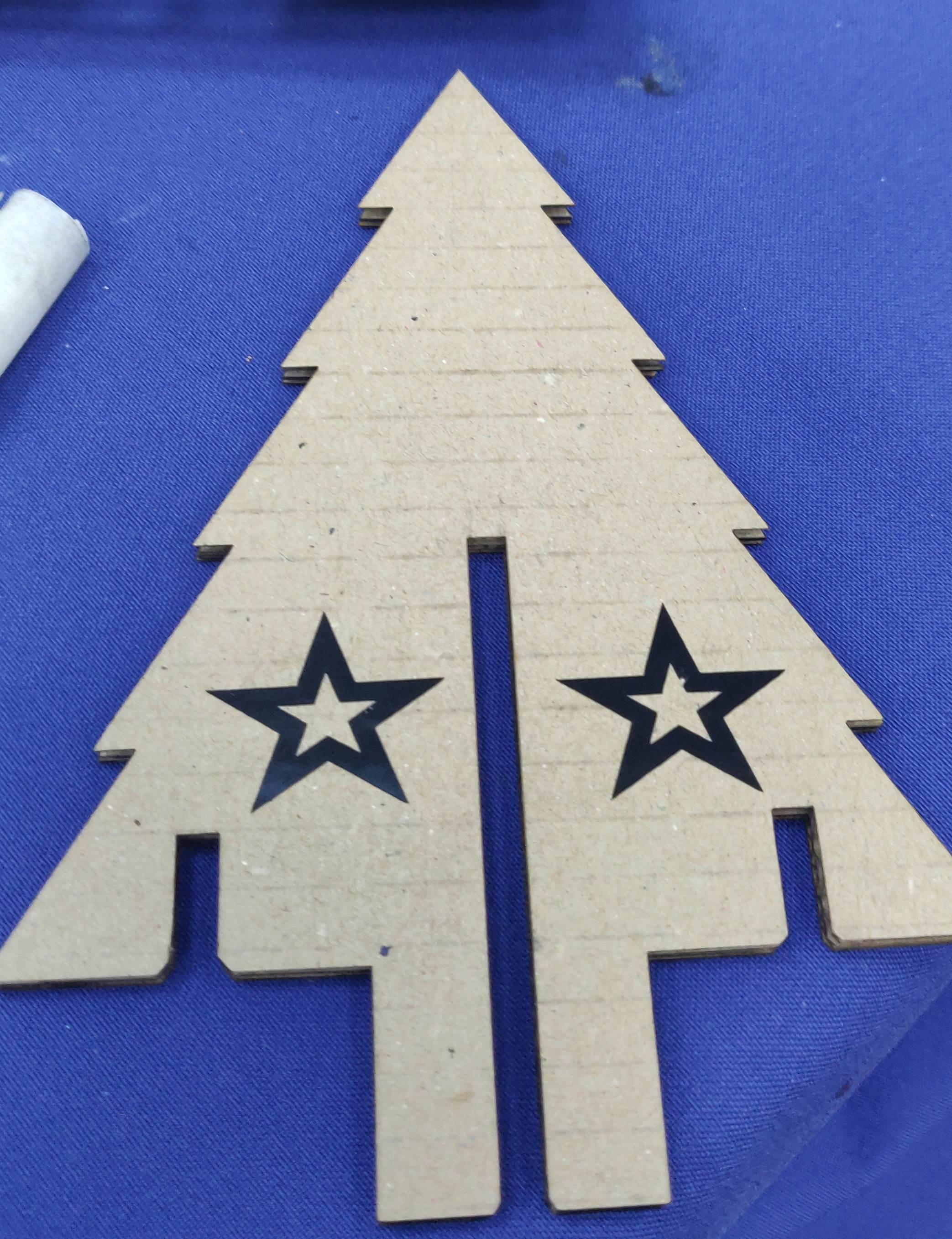
I made a simple design of a symmetrical Xmas tree using a few equivalences to achieve a uniform shape that I liked. I then duplicated (copy and paste) the drawing side by side with it so that I had 2 trees.
-
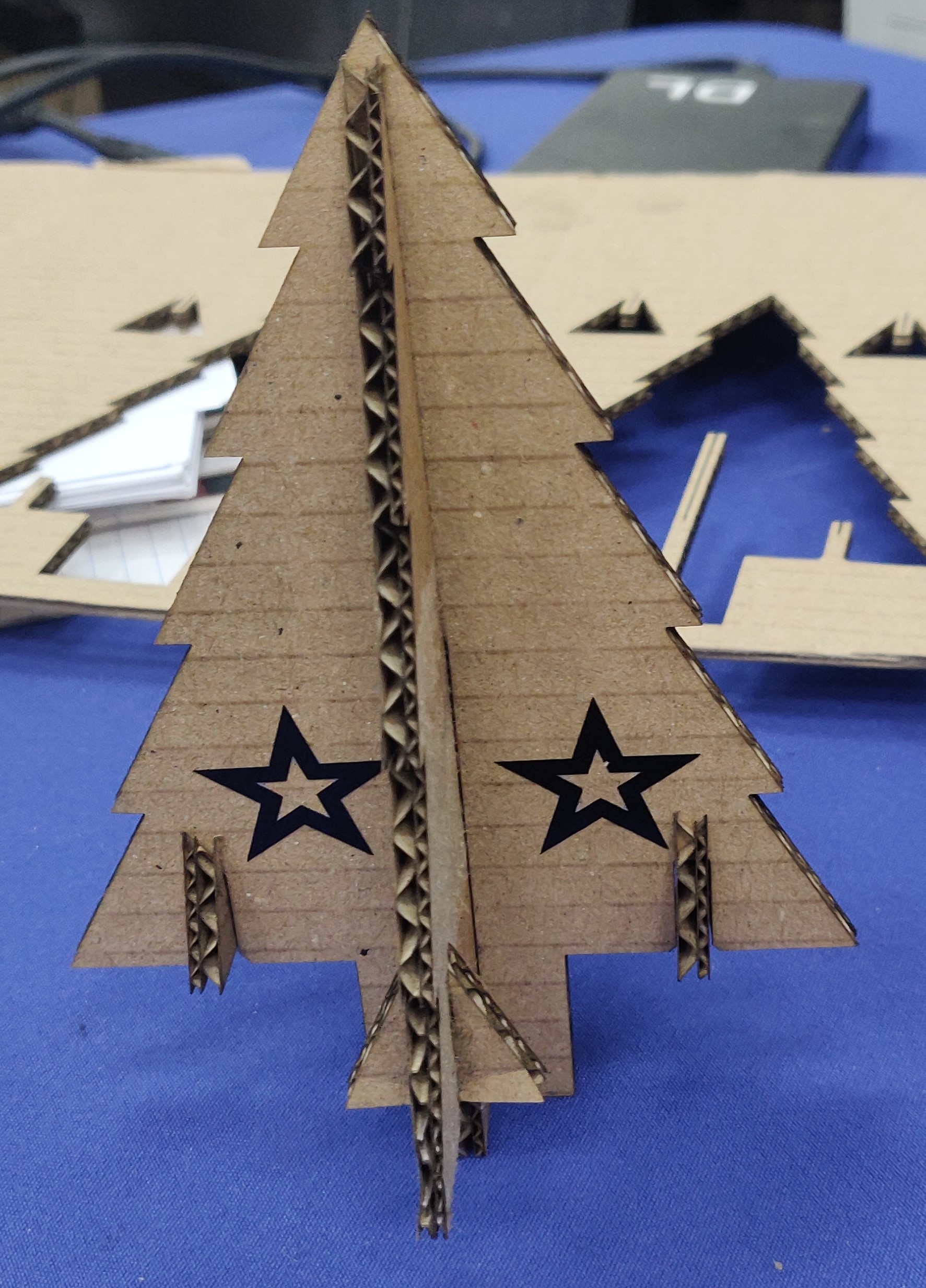
I then created 1 gap down the centre of each tree, hallway down the length. One tree top to middle, the other bottom to middle. I set the width of the gap as a parameter for easy editing if changes needed to made (for different thickness cardboard, or if error were made in our kerf calculations).
-
The dimension of the gap parameter was then set to (cardboard thickness – [kerf*2]). This should give us a tight fit in our laser cut joints. I also put a small chamfer on either entrance to each slot (hard to see in images)
-
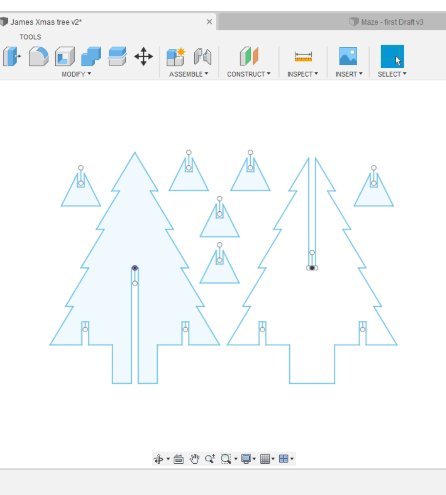
I then made a design of a smaller triangular piece and placed the same dimensioned gap at the top of it, half way down. I also created a gap on the Xmas tree pieces where this gap would fit (4 gaps total, 2 per tree piece). I made 6 copies of this small piece (an extra 2 for good measure). (all these slots were also chamfered)


 There was only one parameter set up for this design. This was the width of the slot cutouts in each of the pieces. This should be set to the measured thickness of the material being cut (in this case cardboard). This design was intended for the laser cutter, where the kerf is negligible, so we ignored it. If we wanted to make the design more universal (so it could be made with a CNC router or another tool), we could add a parameter for Kerf (or merge it into our CUTWIDTH value):
If you want to see a project with a better implementation of parameters you can check out my draft design for part of final project in week 2 Computer Aided Design.
-
Most software for CNC would let us specify if we want to cut our design on the outer or inner edge of the line. If we correctly identify which (outer for this design), then we can ignore the kerf, since the toolpath generated would ensure that all kerf is within the cut material, which only includes the material we want to remove.
-
If for some reason we are forced to use the actual diagram vectors as the cutting lines for our toolpath, then we should compensate for the kerf to get a good fit. However, cutting exactly along the design vectors would mean that every cut would be missing “half a kerf worth” of extra material that the design did not intend to be removed. So I could just calculate the CUTWIDTH as “material thickness MINUS Kerf” (since we have 2 sides to a slot, so two half-kerfs would need to be accounted for to end up with an actual cut that measures the same as the material thickness). This should allow us to still end up with a snug fit of the pieces together, with the final real world slots being the exact thickness of our material.
-
Using a cutting device with a non negligible kerf means that our design should be altered to include dog bones or similar elements. Even if we use proper toolpath software where we can chose to cut along the inner or outer edge of a vector line, we still need to add something like dog bones.
-
I manually entered the chamfers on the entrances to the slots to allow for easier alignment of the pieces when assembling. If I were to redesign this project, I would instead set up those chamfers as an additional parameter so they could be easily altered.
- The CAD file (Fusion’s native f3d format): Xmas Tree Fusion 360
Stangely Fusion 360 doesn’t let you export your design as an SVG without adding a plugin. I found a relatively easy way to convert my file to SVG was to:
- extrude the drawing slightly in fusion
- export the file as an STL
- open up a blank 3D file in [TinkerCAD](https://www.tinkercad.com/)
- import the STL file
- export the tinkercad version as an SVG
Cut and Construction:
-
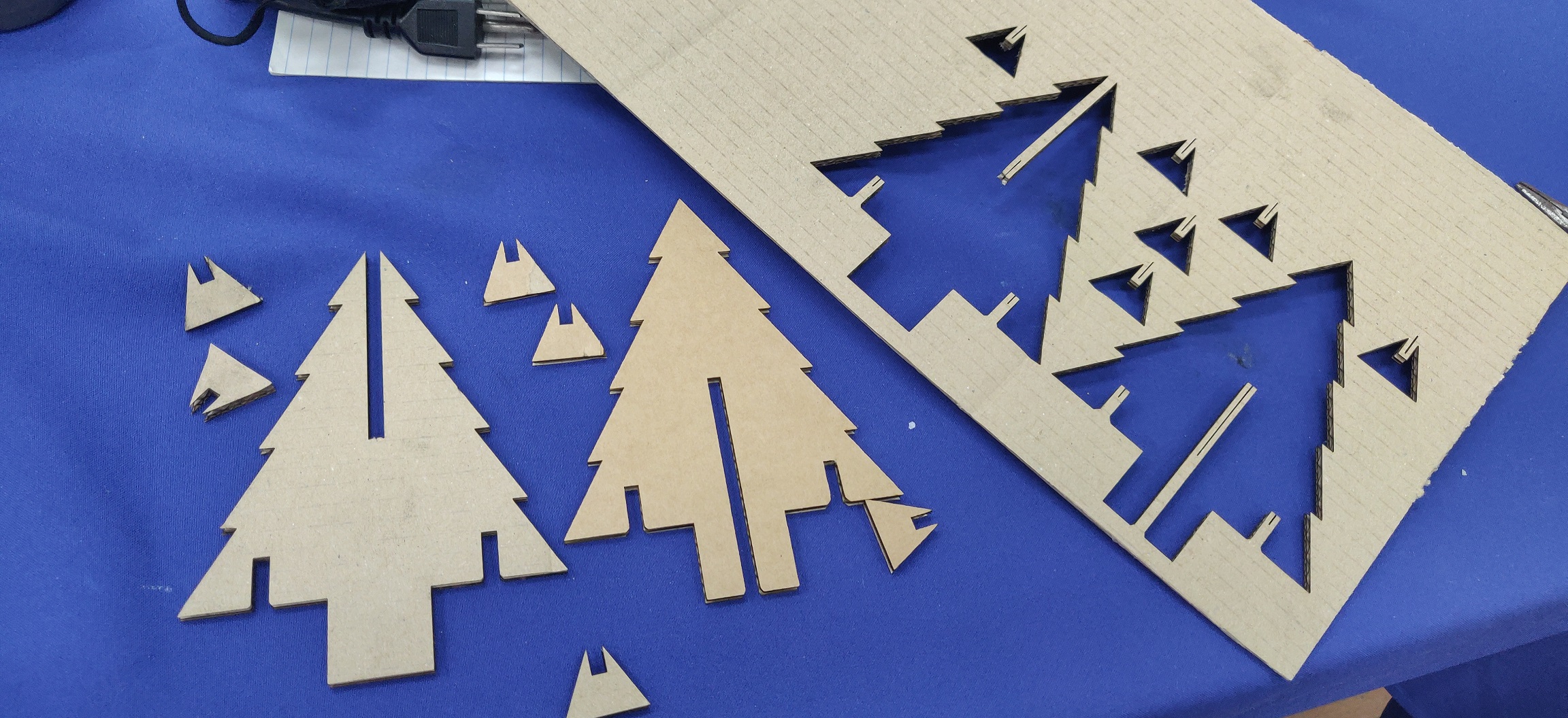
I outputted the final drawing to an DXF format, imported the drawing into CorelDraw on the computer attached to the laser cutter (a separate computer was used for designing and cutting), and then “printed” the job to the laser cutter.
-
Then remove the individual parts from final cut sheet.


Vinyl cutting:
-
I used a vinyl cutter (Roland Camm-1) to create a very simple piece of decoration for my laser cut tree.
-
It was a very simple star design with a smaller star inside.
-
The design was made in Inkscape, then imported into Cut Studio and “printed” onto the vinyl.
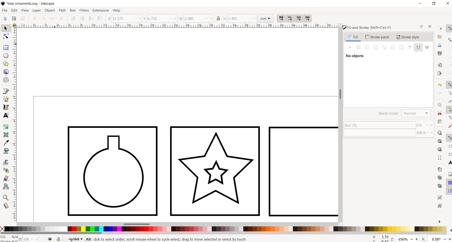
Simple svg file: tree ornaments SVG
- Then stuck on the tree.
The most interesting part of this week’s lesson was learning about the various types of joint possibilities that can be used. Although I used the most basic joint for this project (chamfer), I look forward to trying some of them out when I make more complex designs
