
Output Devices
Group assignment:
- Measure the power consumption of an output device
Individual assignment:
- Add an output device to a microcontroller board you've designed and program it to do something
Individual Assignment:
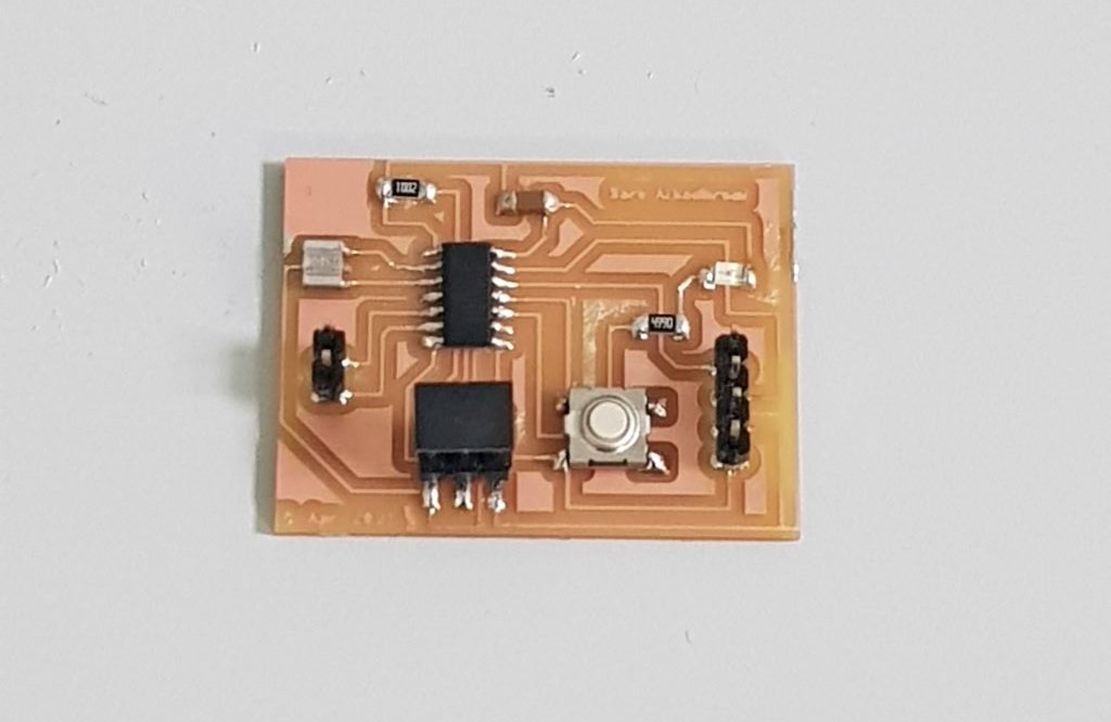
In this week I used the board I designed in Input Devices week to connect an output device with it. The board consists of the microcontroller ATtiny44, one LED, button and six pin headers. The output device I used is the DC Buzzer and Neopixel LED.
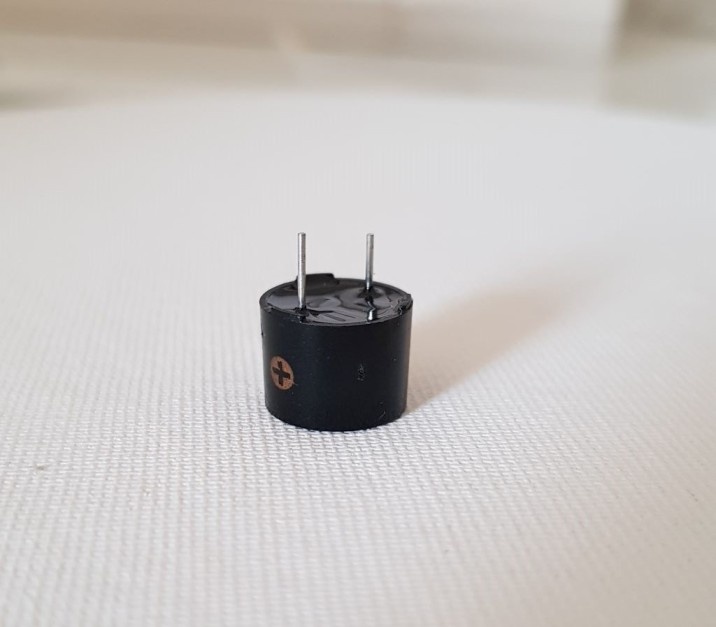
DC Buzzer is an output device that generated beep sound.
I put the design in the milling machine then I soldered the components and I checked the continuety between the connected components.
After that I used jumer wires to connect the DC Buzzer with the board. I connected the positive pin in the buzzer with pin A1 in the microcontroller and the negative pin in the buzzer with GND in the board.
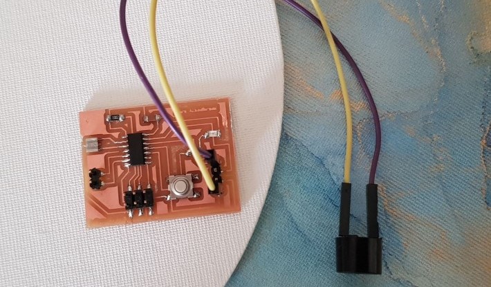
Then I wrote a code to connect the buzzer with the button I have in the board. Since the buzzer (OUTPUT) is connected to pin PA1 and the button (INPUT) connected to pin PA2 in the ATtiny44, I used these pin numbers for programming.
PA1 (ATtiny44) = A1 (Arduino)
PA2 (ATtiny44) = A2 (Arduino)
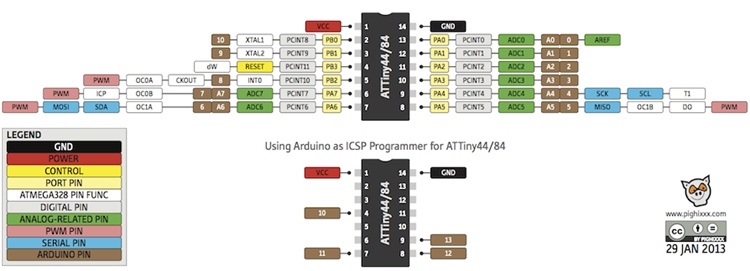
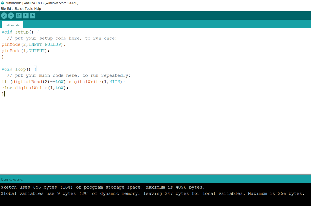
To use the button properly, I have to activate the pullup resistor in the ATtiny44 microcontroller. To do so, I used the code pinMode(2,INPUT_PULLUP) and I declared pin 1 as an output. Then I used If statement to inform the buzzer to generate sound (HIGH) when the button is pressed (LOW). Since I cennected the button with GND in my PCB, it become LOW when I press it.
Neopixel LED
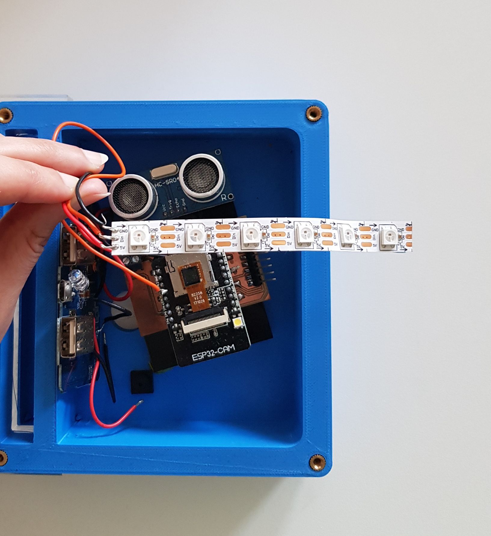
In my final project I used an output device (Neopixel LED). I used the PCB I designed for my final project that is controlled by using esp32 microcontroller.
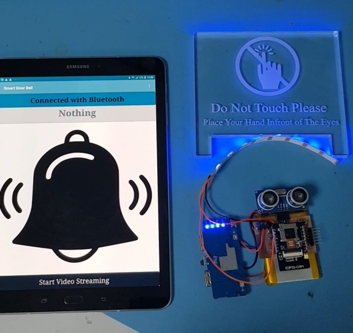
I used a strip of 6 LEDs
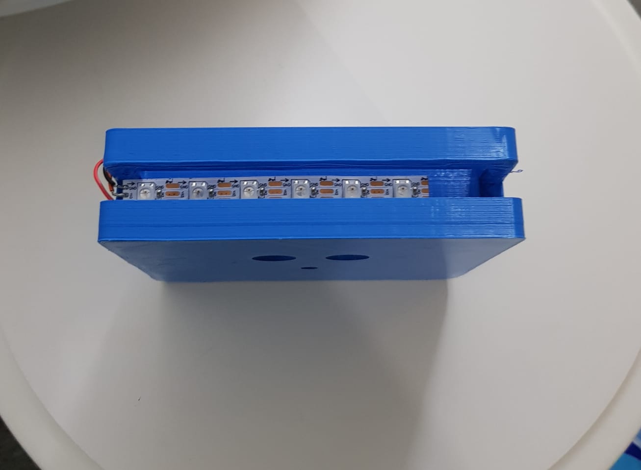
Neopixel strip has VCC, GND and digital pins.
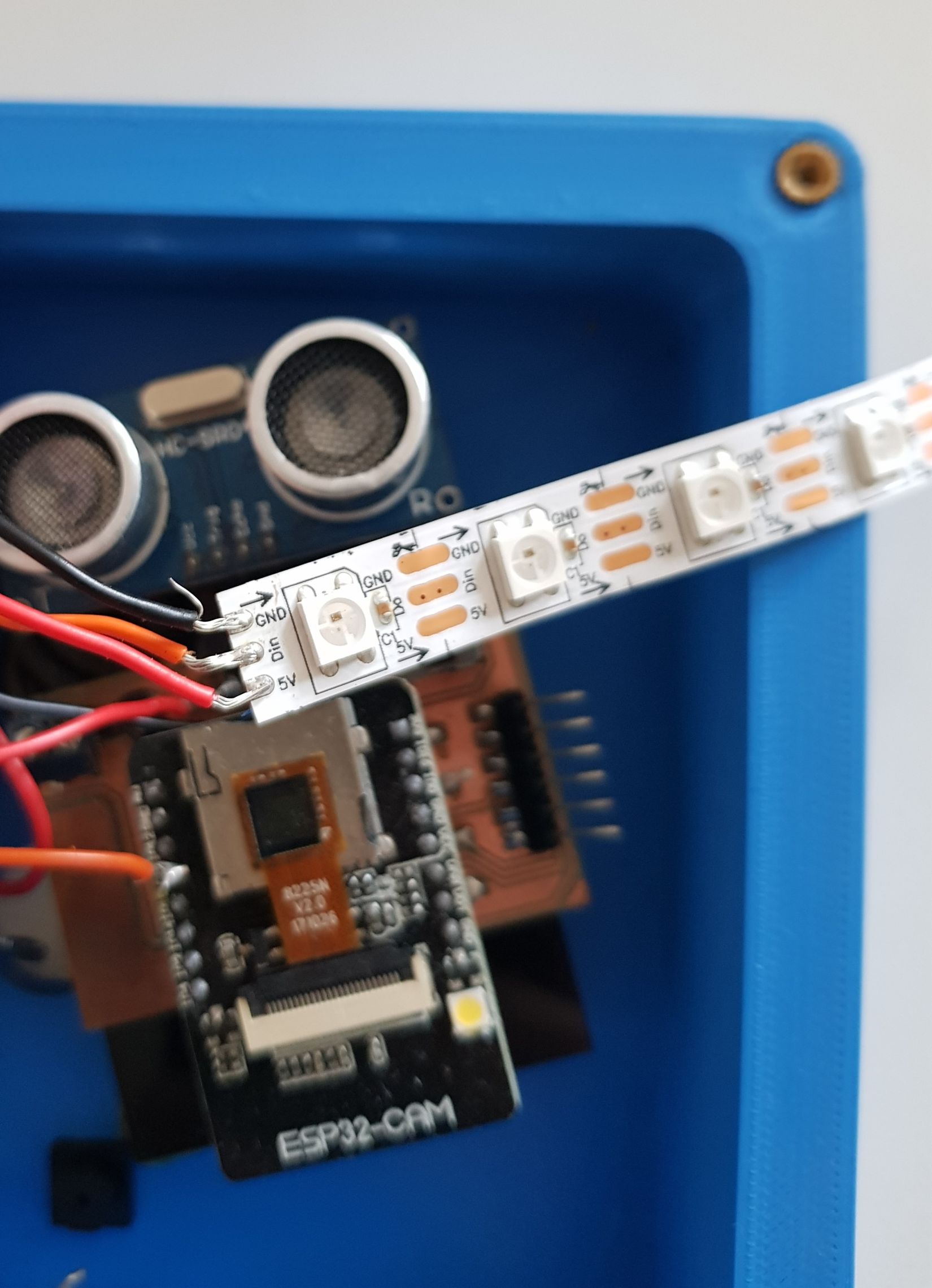
I connected the digital pin in neopixel with pin13 in esp32cam by using orange wire and I used red wire for the VCC and black wire for the GND.
I used the example code from arduino IDE and I modified it to work with my pcb and light up with blue only. The complete code is attached below in the files list.
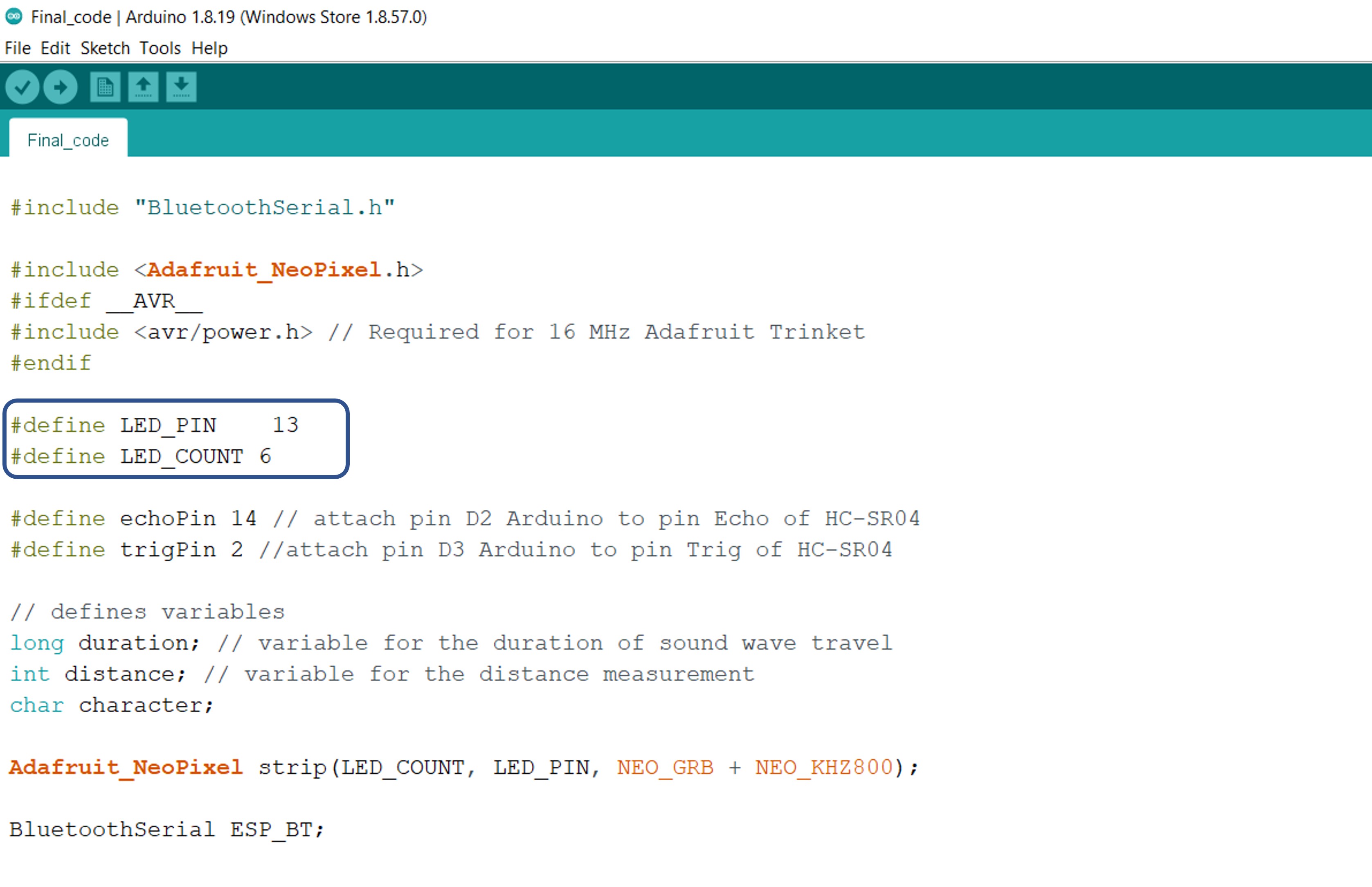
I uploaded the code to my pcb by using FTDI cable. Then I connected the pcb with the battery and it immediately lights up as shown in the following video.
Group Assignment:
Group Page LinkI connected the output device (DC Buzzer) to the PCB I designed and I used DC Power Supply to provide 5V to the PCB to check the current in the closed circuit. As shown in the following video, the current is 0.1A
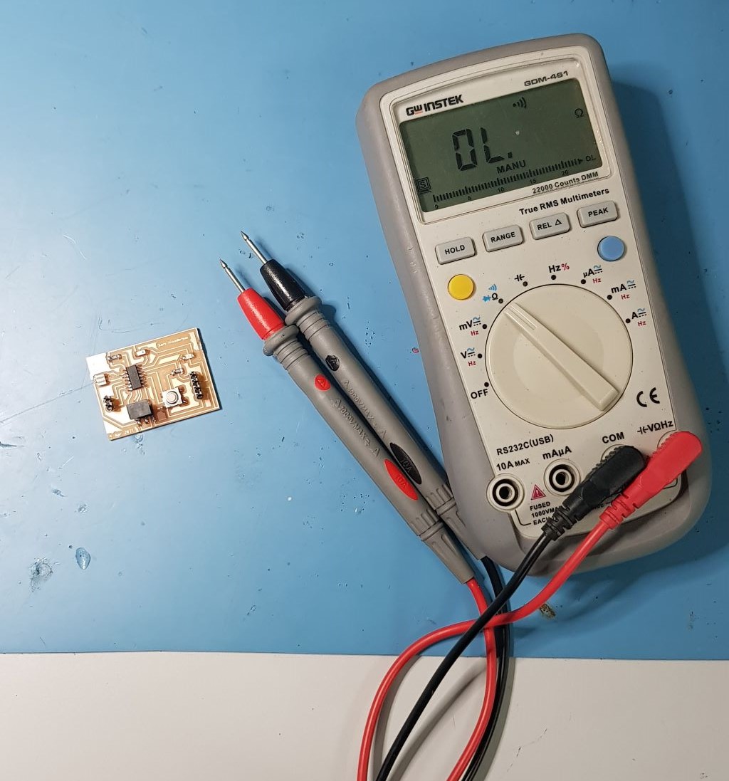
Then we used Digital Multimetere to measure the current and compare the two values shown on the power supply and the multimeter. As shown in the following video, the measured current equals to 0.0918A approximately and on the power supply equals to 0.09A.
Files list:
| PCB Schematics | Eagle File |
| PCB Board | Eagle File |
| DC Buzzer Code | Arduino IDE File |
| Neopixel Code | Arduino IDE File |
Close Project