14. Networking and communications
Individual assignment: design, build, and connect wired or wireless node(s) with network or bus addresses.
Group assignment: Send a message between two projects.
Bluetooth
Learning How to Use Bluetooth Modules
Bluetooth is a communication protocol that exchanges data wirelessly. It operates the same way a serial bus works, by sending and receiving data over TX and RX via a COM port, but wirelessly. I want to be able to send messages between a processing application on my computer and a motor board for my final project via the bluetooth HC-05 module . So, I started by watching this video:
Note: The video is technically about the HC-06 module, not the HC-05, but the differences (for my purposes) were negligible, and I found this video to be very helpful and easy to comprehend.
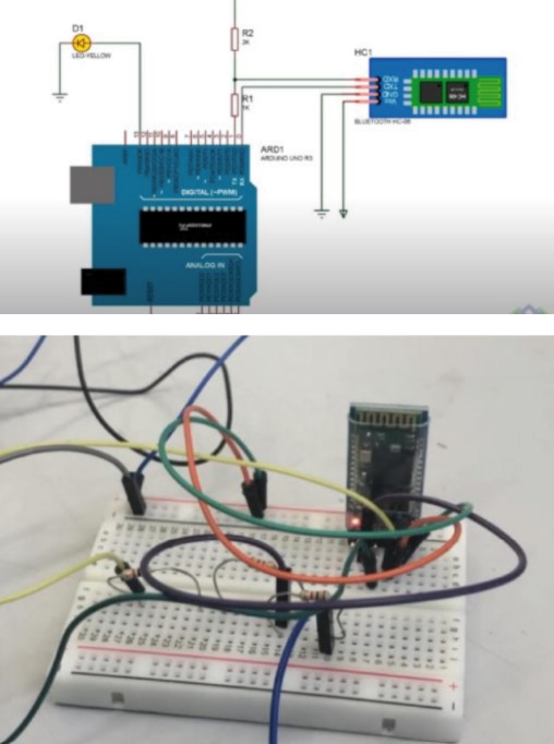
I started by following the tutorial with a breadboard and creating basic communication. The wiring diagram from the video:
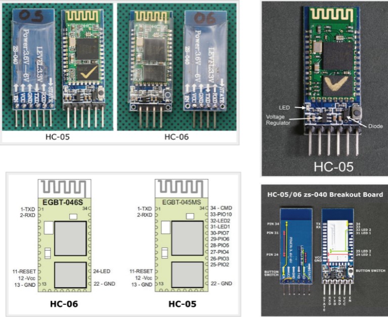
The image above shown the differences between HC-05 VS HC-06
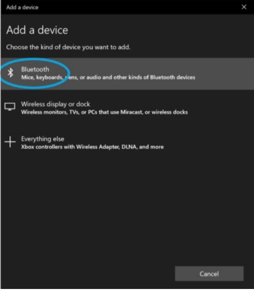
The built in LED of the bluetooth module should be blinking rapidly. This indicates that it is being powered. Next, I paired the bluetooth module to my windows surface computer.. The steps to do that are as follows: Go to settings. Navigate to “Bluetooth & Other Devices.”
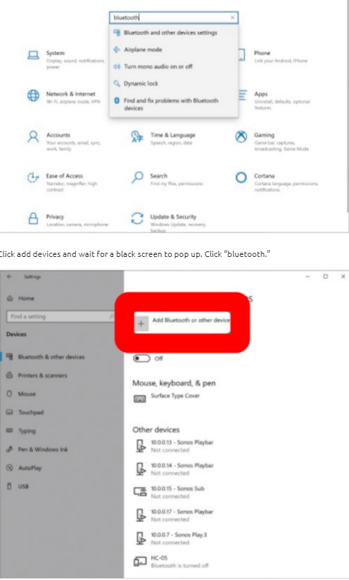
Click add devices and wait for a black screen to pop up. Click “bluetooth.”
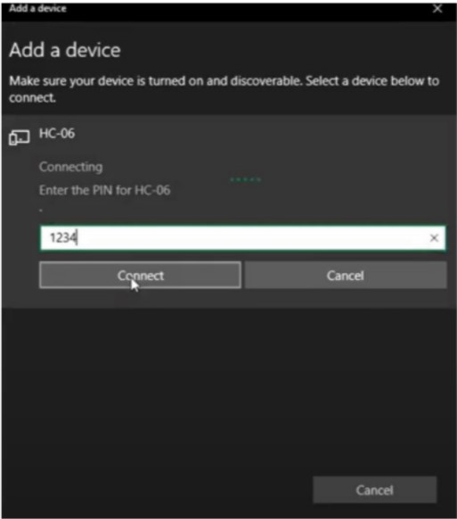
It will buffer for a while. Click on the bluetooth module when it pops up. Enter the default password “1234.”
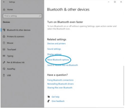
You need to know what COM port the bluetooth device is associated with. To do this, scroll to the bottom of the page. Select “More Bluetooth Options.” Wait for the pop up menu to appear on screen. Click on the tab that says “COM Ports.” There are 2 COM ports indicated for the HC device. I will use the Outgoing COM port, the one used to transmit data from my computer to the bluetooth chip. The Incoming data COM is for transmitting data from the hardware the bluetooth chip is connected to over to a computer.
code:
import processing.serial.*;

Serial sonic_port; //outgoing btSONIC port
String string;

void setup () {
  //open ports
  sonic_port = new Serial(this, "COM11", 9600);
  sonic_port.bufferUntil('\n');
}
void draw() {
  printArray(string); //prints (string) to processing text area
}
void keyPressed() {
  if (key =='1'){sonic_port.write('1');}
    if (key =='0'){sonic_port.write('0');}
}

void serialEvent(Serial sonic_port) {
    string = sonic_port.readStringUntil('\n');}
Arduino Code:
int x;

void setup() {
  Serial.begin(9600);

}

void loop() {
  if(Serial.available()>0){
    x = Serial.read();
  }

  if (x== "1") {
    Serial.println("Hello Processing");
  }

  else if (x == "0") {
    Serial.println("by processing");
  }
}
You can do this in powershell by following the instructions on How do I read/write data from a Serial Port After you type in powershell, type in the following line to create a port variable and assign it to the com port of the bluetooth module. Note- the arduino (attached to the same com port as the bluetooth module) should not be attached to the computer you paired the bluetooth module with. Processing should be running on one computer, the one that is paired to the bluetooth module/arduino, and the module/arduino should be plugged into another computer, where you run powershell.
Line 1:
$port= new-Object System.IO.Ports.SerialPort COM3,9600,None,8,one, hit enter
This should initialize the port variable and attach it to the port “8” that the bluetooth module is attached to. Hit enter
Line 2:
$port.Close()
This should close the port. Hit enter.
Line 3:
$port.open()
Opens the port. Hit enter.
Line 4:
PS> $port.WriteLine(“Hello world”)
Writes “Hello world” to arduino serial port, which is connected to tx and rx of bluetooth, allowing the bluetooth to transmit this to processing.
It does kind of ignore most of the code that tells the arduino to print “Hello world” if key 1 is pressed, so I just deleted that part. With this test, I really only wanted to test if I could initiate contact anyways. After I closed the port with powershell, It worked:
Connection Setup
The main Idea of my assignment was to use the Attiny board that was previously designed and manufactured as the first node and Arduino Uno as the Second node. with the help of a smartphone and App designed in the application programming week, I used the HC06 Bluetooth module, to send different numbers like 1 for node 1 and 2 for node 2 and the respective nodes would blink and Send a message via Bluetooth that says which node it is.
As shown in the image below The ATtiny is connected to the hardware serial port of the Arduino Uno and the Bluetooth.
Programming
As shown in the code of Node 2 the Bluetooth module Communicates using Software serial communication named serial (notice that hardware serial is Serial with capital ‘S’) hence the difference. When a message (in our case address) is sent via Bluetooth, Node 2 checks if the address is ‘2’ then it corresponds to its address and responds by Lighting the LED for 2 sec as well as sending a message to the Bluetooth saying “This is Node 2”. The message gets printed on the smartphone’s screen. However, If the address sent is not ‘2’ then Node 2 forwards the Address to Node 1 (as shown in the code). When it Reaches at Node 1 if the address is ‘1’ then Node 1 Lights up the LED for 2 sec and forwards a message “This is Node 1” to Node 2 which as seen from the code also sends it to the Bluetooth in order to be printed on the smartphone’s screen. This is achieved by using the String Variable Text which has been put in a for loop in order to combine all characters sent by Node 1 ( Notice that here Hardware serial is used which doesn’t interfere with the Software serial of the Bluetooth). The characters are converted from decimal to Characters by using the Typecast char() .
Finally, the Message gets printed via bluetooth by using serial.print(Text) (notice the small ‘s’ as the bluetooth uses Software Serial).
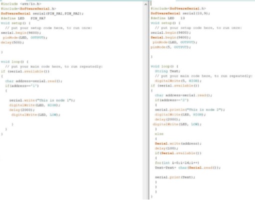 Codes for Node1 and Node2
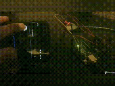
Output
The output is as shown in the video below.
Group assignment
For this week the group assignment is Send a message between two projects. Two projects means needing to send a message between any combination of boards, computers and/or mobile devices.
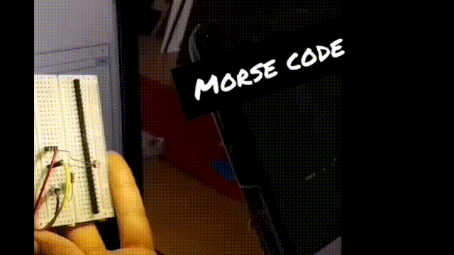
The group assignemnt is between a microcontroller board, a smart phone and a PC. The mobile phone sends morse code by flashing the mobile flash light to a certain message, The microcontroller with a light sensor attached interprets the signals and displays them on the PC screen via serial.
morse code:
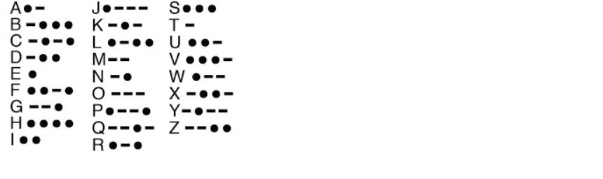
Morse code is a method used in telecommunication to encode text characters as standardized sequences of two different signal durations, called dots and dashes or dits and dahs. Morse code is named after Samuel Morse, an inventor of the telegraph. Its a fascinating method of communication used historically as an easy way of encoding and sending text over long distances.
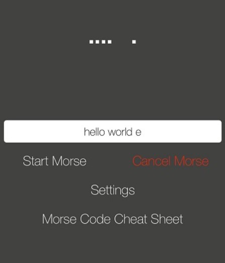
Morse Code Torch
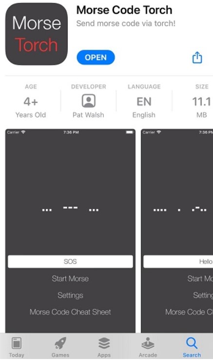
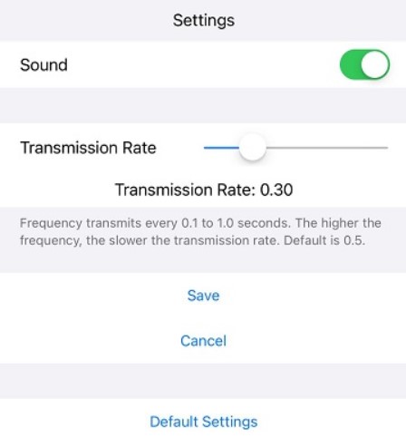
Morse Code Torch is an app that allows you to encode your messages into morse code using your phone’s flashlight. Used on an iphone here. I tried other applications but none of them allowed me to adjust the transmission rate time or even mentioned what rate they were using. This application offers flexibility when it comes to doing that which comes in handy for writing the code.
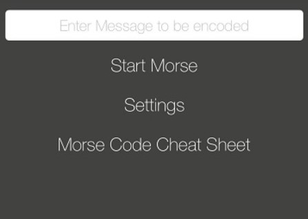
The application is pretty easy to use, you just write a message and the phone flashlight flashes in dashes and dots cooresponding to the message.
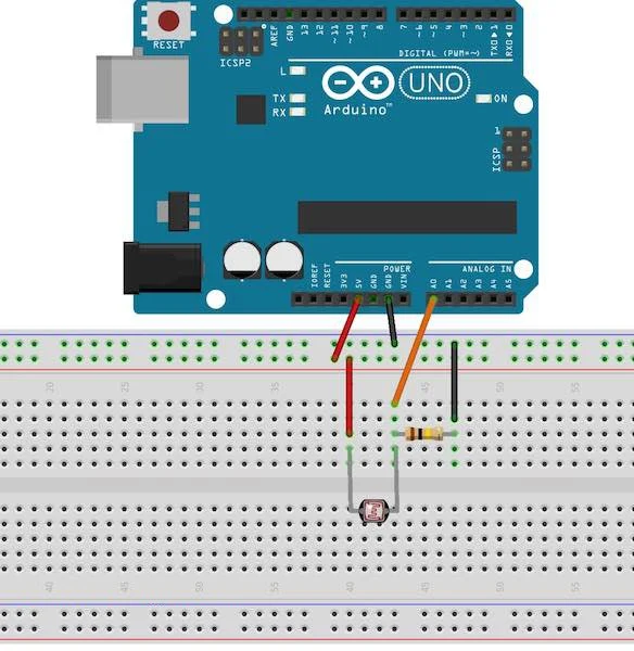
The microcontroller
The microcontroller board used is an Arduino Mega 2560. Which is a microcontroller board based on the ATmega2560. It has 54 digital input/output pins (of which 15 can be used as PWM outputs), 16 analog inputs, 4 UARTs (hardware serial ports), a 16 MHz crystal oscillator, a USB connection, a power jack, an ICSP header, and a reset button. The Arduino mega is frankly an overkill for this project as any attiny44 based microcontroller would easily be able to do this, but it was the microcontroller board available.
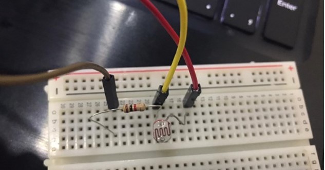
connection
A photoresistor (acronymed LDR for Light Decreasing Resistance) was used to detect the light signals. An LDR works by decreasing resistance with respect to receiving luminosity (light) on the component’s sensitive surface. The LDr can be connected to a microcontroller board via a voltage divder configuration where the voltage that appears at the analog input will vary depending on the amount of light hitting the LDR.

code The code is largly based on krobro‘s code meant for the Duinobot board with some adjustments.
// morse code
// The value of THRESHOLD is dependent on your ambiant light ... it
// may need to be adjusted for your environment.
// original code by krobro  https://gist.github.com/krobro/4eb81265cb09cc28a8c7
//  edited by Duaa

#define DEBUG_PRINTLN(str,data)  Serial.print(F("_DEBUG: "));  Serial.print(str); Serial.println(data);
#define DEBUG_PRINTLN(str,data) // DO NOTHING

#define THRESHOLD 200
#define DOT 200
#define lightPin A1

char morse[6];
int morse_index = 0;

boolean _state;
unsigned long _millisStart;
unsigned long _millisEnd;

static char *_list[26] = {".-",       // 'a'
                          "-...",     // 'b'
                          "-.-.",     // 'c'
                          "-..",      // 'd'
                          ".",        // 'e'
                          "..-.",     // 'f'
                          "--.",      // 'g'
                          "....",     // 'h'
                          "..",       // 'i'
                          ".---",     // 'j'
                          "-.-",      // 'k'
                          ".-..",     // 'l'
                          "--",       // 'm'
                          "-.",       // 'n'
                          "---",      // 'o'
                          ".--.",     // 'p'
                          "--.-",     // 'q'
                          ".-.",      // 'r'
                          "...",      // 's'
                          "-",        // 't'
                          "..-",      // 'u'
                          "...-",     // 'v'
                          ".--",      // 'w'
                          "-..-",     // 'x'
                          "-.--",     // 'y'
                          "--..",};   // 'z'

// convert_morse
//
// convert morse code (such as "--..") to a
// letter ('z')
//
// code - the morse code to convert
//
// Returns - converted letter or '?' on failure
//
// Notes: inefficient linear search ... too slow?
//
char convert_morse(char *code)
{
  DEBUG_PRINTLN("CONVERT: ", code);

  for (int x = 0; x < 26; x++)
  {
      if (strcmp(_list[x], code) == 0)
      {
        DEBUG_PRINTLN("GOT: ", (char)(x+'a'));
          return (char)(x + 'a');
      }
  }

  // could not decode what was read
  return '?';
}

void setup() {
  Serial.begin(115200);
  delay(2000);

  _millisStart = _millisEnd = 0;
  _state = LOW;


  Serial.println (" ");
  Serial.println ("Finished setup ...");
}

void loop() {
  /* uncomment the line below to test and find the light threashold in your enviorment.
   *  comment it again after adjusting the threashold value
   */
 // Serial.println (analogRead(A1));
  boolean  state;

  // read the light sensor ; sensor can be HIGH or LOW
  if (analogRead(lightPin) <= THRESHOLD)
  {
    state = LOW;
  }
  else
  {
    state = HIGH;
  }

  // check to see if the current state of the sensor
  // matches the last state of the sensor.
  if (state != _state)
  {
    _millisEnd = millis();

    if (_state == HIGH)
    {
        // Just finished a HIGH state and transitioned to a low state
        // did we just process a dot or a dash?
        if (_millisEnd - _millisStart < DOT + DOT/10 )
        {
          morse[morse_index] = '.';
          Serial.print(".");
        }
        else
        {
          morse[morse_index] = '-';
          Serial.print("-");
        }

        // just finished reading another dot or dash
        // append the dot or dash to the morse to decode
        morse_index++;
        morse[morse_index] = '/0';
    }
    else
    {
      // just finished a low state and transitioned to a high state
      //  Was a character, letter or word just finished?
      if ( _millisEnd - _millisStart < DOT + DOT/10 )
      {
        // single dot low state ... finished a dot or a dash
      }
      else if ( _millisEnd - _millisStart > DOT*3 - DOT/10 )
      {
        // 3 dot low state or 7 dot low state ... finished a letter
        char c = convert_morse(morse);
        if (c =='?') {
          Serial.println(" *** Failed to decode properly ... retrying ...");
        }
        else
        {

          Serial.println(c);
        }
        morse_index = 0;

        if ( _millisEnd - _millisStart > DOT*7 - DOT/10 )
        {
            // 7 dot low state ... finished a word
            Serial.print(' ');
        }
      }
    }

    // set the current state
    _state = state;
    _millisStart = _millisEnd;
  }
}
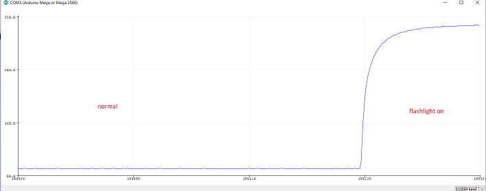
The first step is to check the light thrashold for normal room lighting vs flashlight pointed at the LDR. This value changes from enviornment to enviornment. A quick test showed at at normal condition the value is around 90, and with the flashlight pointed it was around 300. So the thrashold was set at 200.
Results
With that, the microcontroller was ready to decode morse code. Here is a video of the microcontroller decoding “hello world” in morse code.
Hero Shoot!!