Electronics Production
For our group assignment we started working together on the Milling Machine in order to better comprehend how to use it properly and how to set the right axis along the way.
We had some problems during the process, since started milling with Alberto’s board and we failed to tighten the housing enough - the machine let the drilling bit fall down, and it stopped quite rushly. We were really worried for an hour or so because our instructors had to fix it and understand what happened, and then we started again to work.
With a bit of more caution we started working on our group assignment.
We had to check the dimensions of the file in Mods and prepare the file step by step:since we did this after each one of us already finished milling it’s own board, it was quiet easy.
We used the mods in order to have the .rml file for traces and outline. We upload the png models and we left the automatic settings. The only mode we changed was the origin of the axes from 10 to 0.

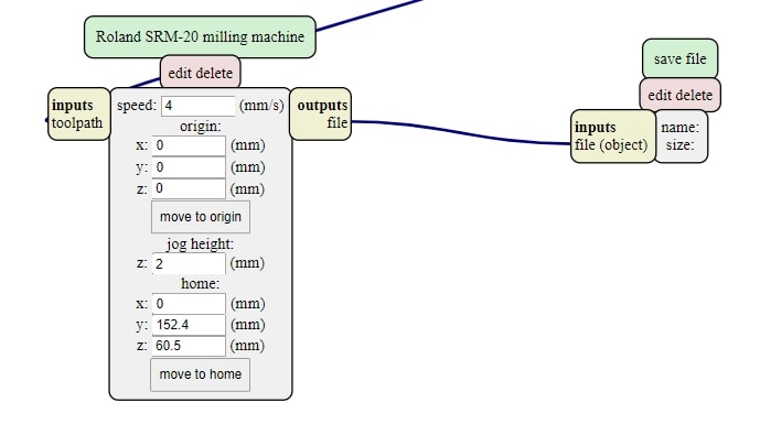
At this point, we started to set our milling machine. We used a 1/64 bit for the traces and a 1/32 bit for the outline . After setting the copper board and securing it with a double tape stick, we set the origins (X,Y,Z) on the milling machine moving the table to find the starting point. After that, we set the origin on the VPanel SRM 20. To find the Z, we moved the chuck downwards until it was near the table, then we used the hex wrench to loosen the tip, make it touch the table holding it firmly and then tight it up again.

It worked out, but since we had only one drilling bit and it had already lost its tip, we had to mill the board with what we had and it didn’t turn out perfect.

Below the resulting board:

In conclusions we were able to characterize the design rules for our PCB milling machine Roland SRM-20:
- 0.15 inch is the minimum space that the 1/64 bit can cut between the traces
- 0.001 inch is the tiniest trace that the same bit can cut.