Link to Computer Controlled Cutting Group Page
After the meeting with Neil on Wednesday afternoon I decided to go straight into the vinyl cutter and make myself a sticker. I had made quite a few stickers before so this should be ok for me. The issue is that I still am not 100% sure about some of the settings in the vinyl cutter and sometimes it just doesn't cut for a reason I don't know until I just play around. But I hadn't used illustrator before so this is a new area for me to get used to, I am excited!
We have a Trotec Speedy 300, I have be using the laser cutter for about 6 months now and she is getting much better at using it and understanding the settings. We are looking forward to being able to get this done so that our members have more of an idea of what the best settings are for our Speedy 300.
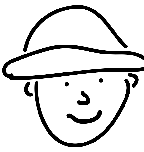
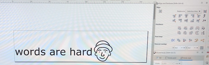
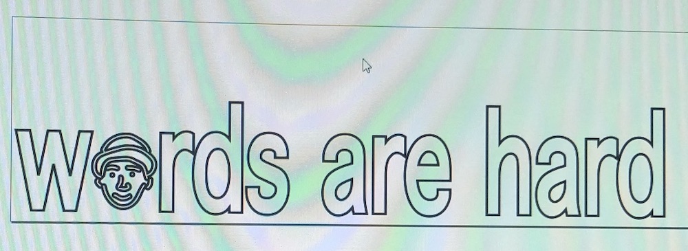
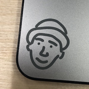
Illustrator is new to me so I started with something very simple, and used wrote a few words which I thought was fitting for me as I sometimes find 'words are hard'. I then decided to add a little drawing of me but a very loose one...
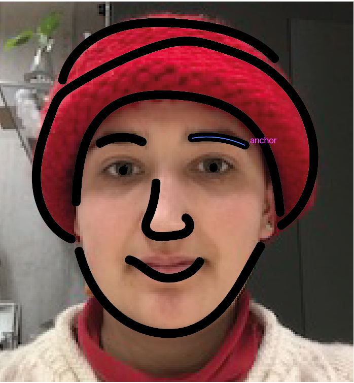
I then thought this doesn't look like me at all and just like I had learnt in fusion you can import an image and then trace over that. This made me get a drawing that still doesn't really look like me but I really liked it so it doesn't matter too much overall.
I then learnt from someone who works in our building that you need to makes the text and the image I had just made into lines so that the machine would understand. Before I was doing this in Inkscape I was just tracing over the image in Inkscape which would always work. But I was struggling to get the image to come out clean which I think is why the vinyl cutter wasn't picking up the lines.
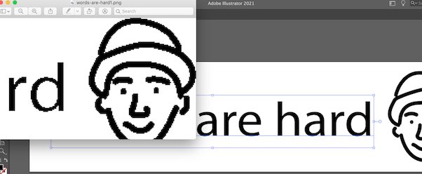
  Text
  - Convert all text to outlines
  - Expand styes such as stroke and fill
  - Path finder merge all overlapping parts

  Saves or export dxf (one of those)

  Image
  - You have to expand
  - Merge
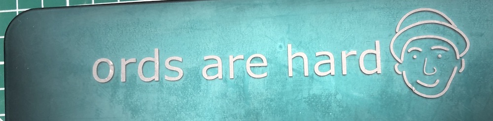
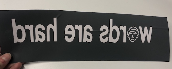
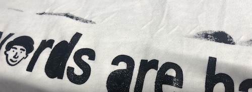
I started by making a small sticker of the design I had made so that I could see what needed to be changed and if it would come out correctly. I worked very well but as I was peeling it to get the negative the 'w' got broken but this made the sticker quite funny as now it says 'ords are hard' with my image next to it.
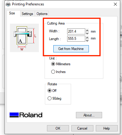
Our vinyl cutter = Roland CAMM-1 GS-24
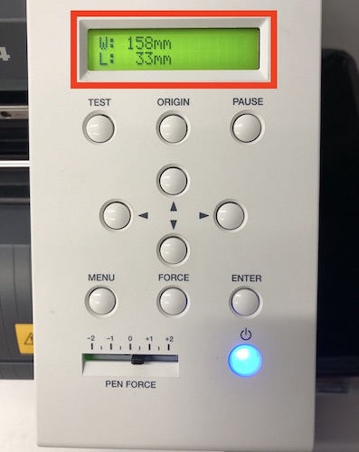
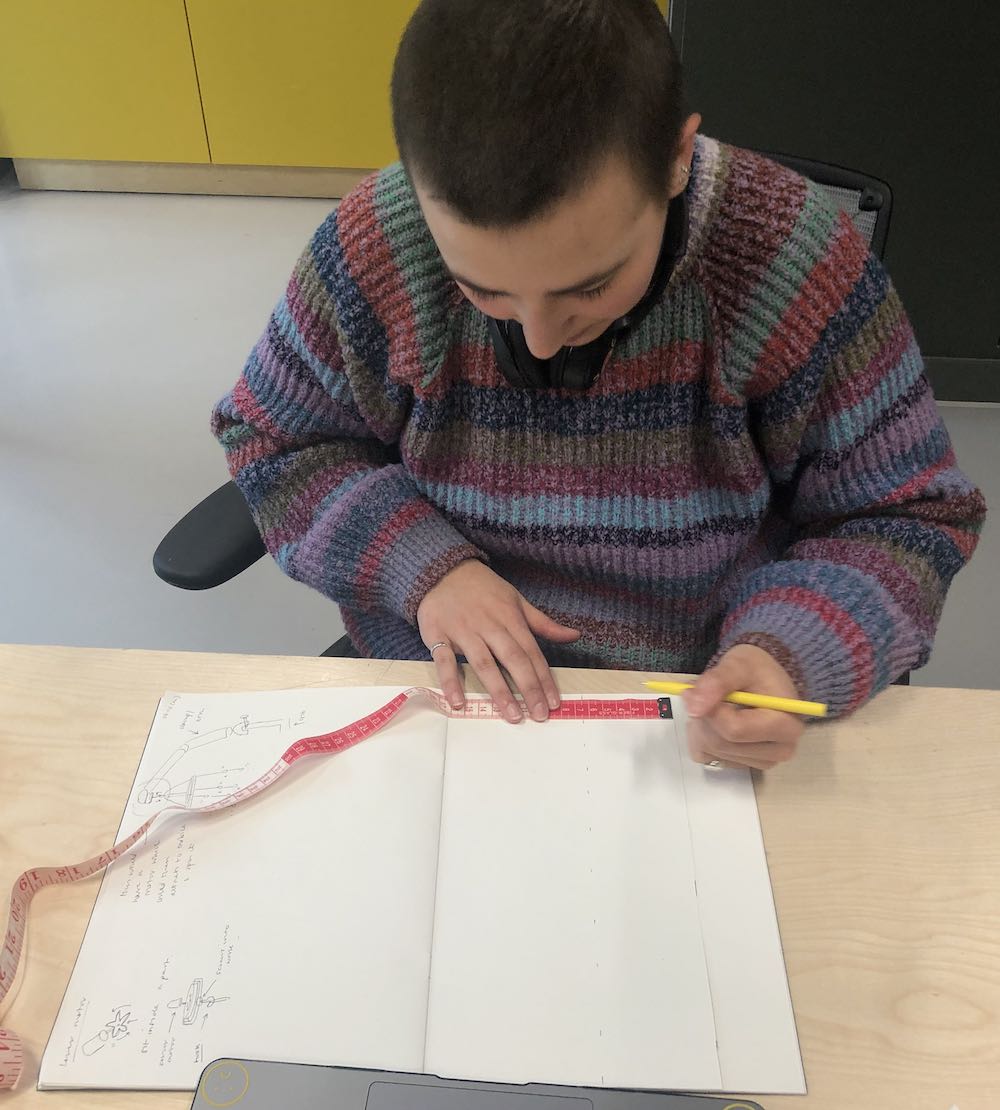
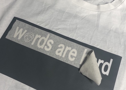
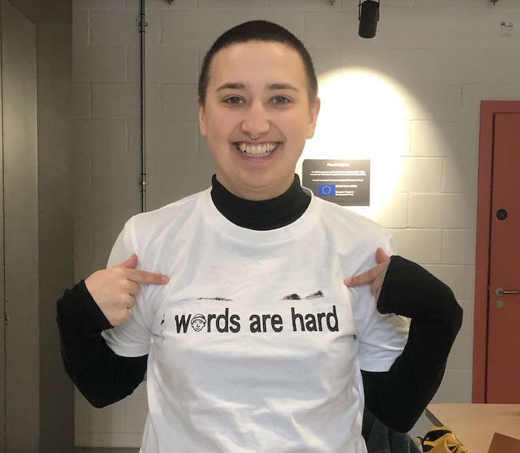
The next day I started on my t-shirt, the first thing to do was measure it out to see what size I needed to make the whole image on my tshirt. I used card to mark out the size so I could get a visual of how it was going to look rather than just eye balling it.
So to put it on the screen printer you a have to print it mirrored so that when you stick it to the screen it is the correct way around. I also decided to more the drawing of me to the 'o' because it on the end just didnt work, it also meant that I could make the whole design bigger so that it could fit on the tshirt better.
Sadly our screen printer was broken so what I ended up doing was printing the design the correct way around. I could then just stick it straight onto the t-shirt and lay the ink on top like I was painting it on.
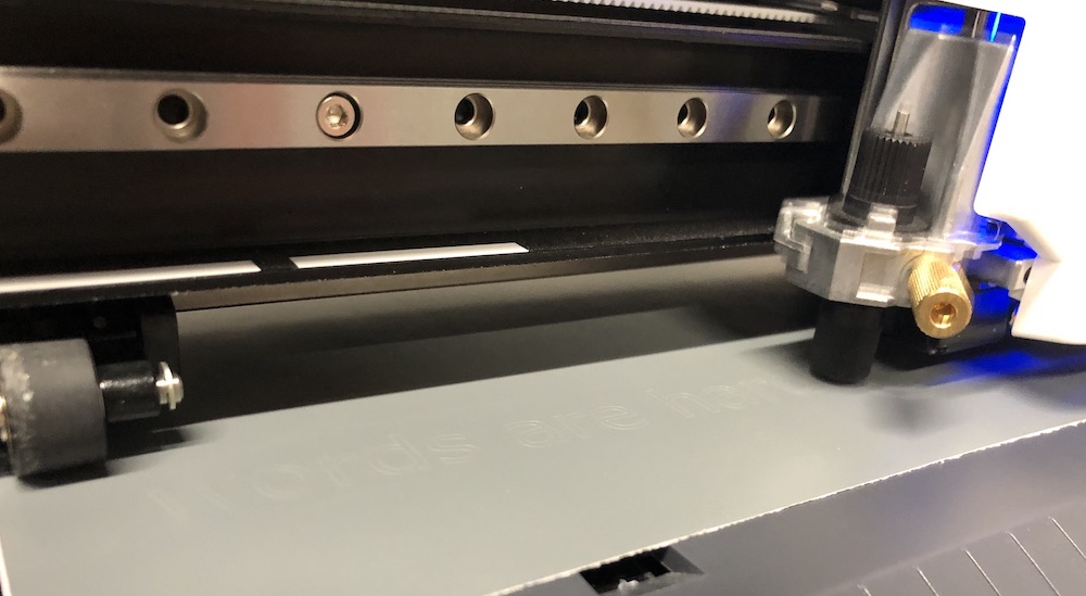
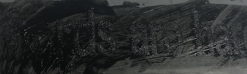
It worked very well, I do think that maybe the ink is a little thick but I am very pleased... don't know if you can tell :)
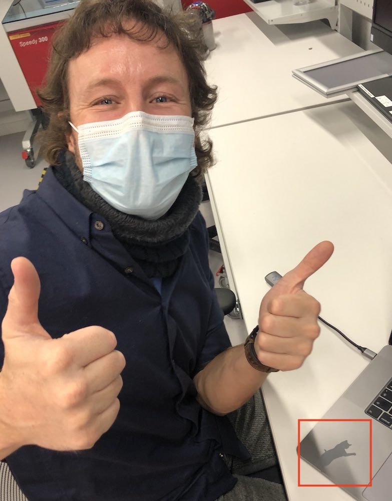
As I am the workshop technician at my work I have to induct the members on the machines, and as Jonny is a member I had to show him how to use the vinyl cutter. I showed him the whole process of how to get your work onto Inkscape and that it needs to be a .dxf or .esp to that it can be turned into a vector drawing. He then did the whole processes himself and made a cat sticker and at the same him I got to make another sticker, all very satisfying as Jonny said himself!
We started on Thursday by Andrew showing us how to get up parametric onto Fusion 360 and how to work with constraints. You have horizontal constraints, vertical, coincident and many more which can all be found on the top bar of fusion. The way to get constraints to work best is to place them in a specific order so that they can be used with the parametric well.
In fusion or other CAD software you would sketch a line and you would type say 50 mm, you now know that that line is 50 mm. But for example that line is the length of a part you are wanting to use more than once and in the future if you needed to change that dimension rather than going into each area. You can set a specific parametric calling it 'line_a' saying all 'line_a' will be 50 mm. So then in your parametric table you can automatically change that variant and all the lines names 'line_a' will be changed from 50 mm to 60 mm. But this is when constraints come in too as without constraints your sketch could come out looking very different.
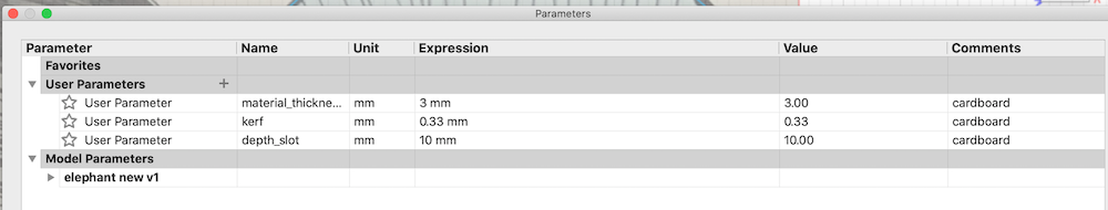
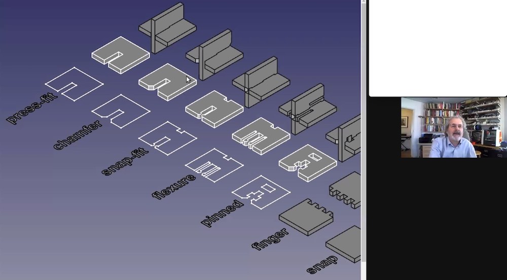
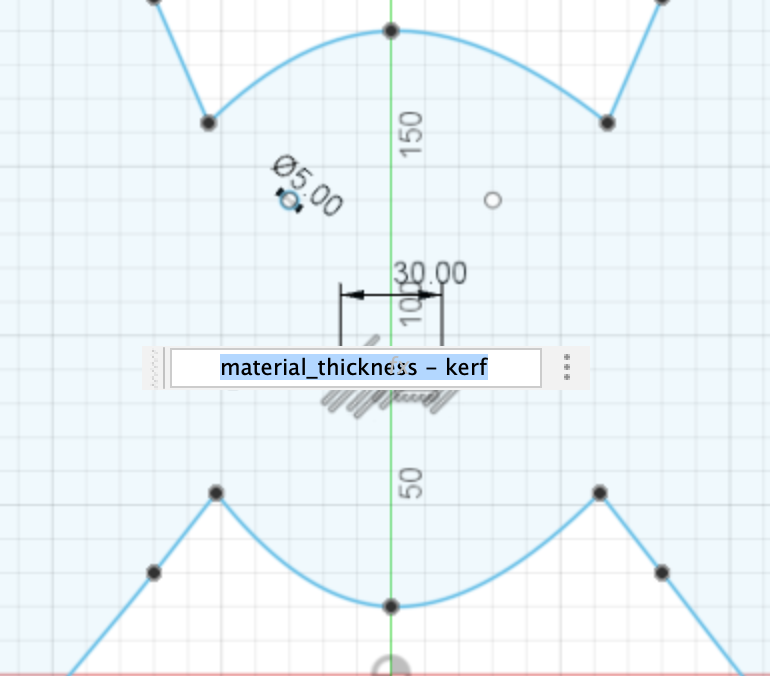
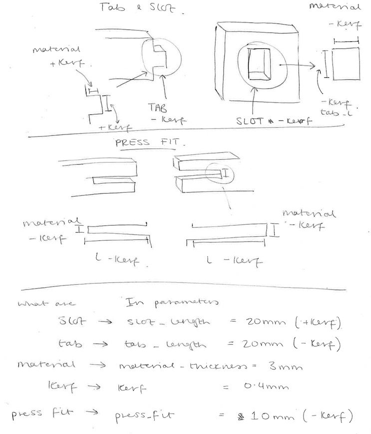
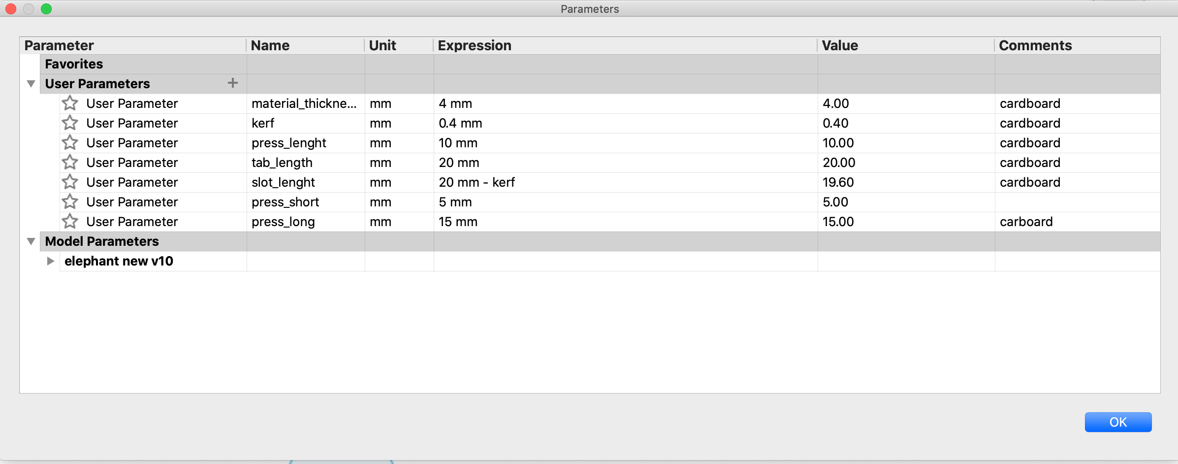
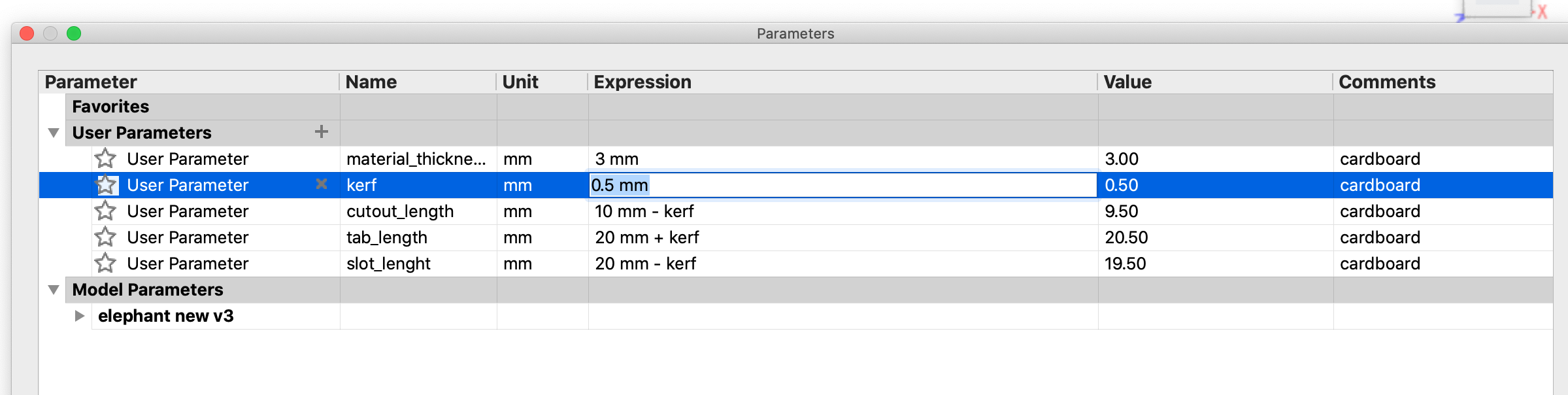
Andrew then started to show us how to do add the kerf onto the parametric which is shown in the image above, you need to make sure you choose the correct symbols in this table. But it does tell you when you are doing it wrong which is really helpful. He also showed us some drawings to make it easier for us to understand when you have to minus kerf and plus kerf, this was one of the areas I really struggled with. Getting my head around when it was just the material and not the kerf as well. Neil also talked a bit about joins on the meeting on Wednesday which I took a screenshot so I could look back and see what other joins are the best.
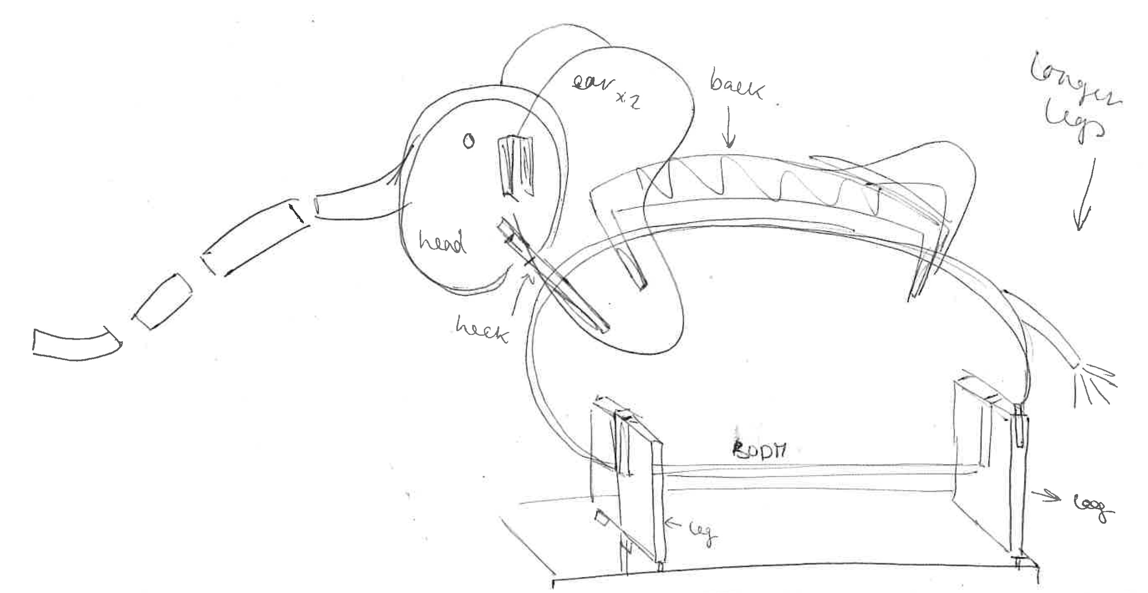
I started by drawing my idea, I was struggling to get my head around what to make. I just wasn't sure what to make or how it was going to come out. So Jonny helped me by just asking what my favourite animal was and there I decided to make an elephant. I started by thinking I was going to make the whole body of the elephant which was going to attach to a piece and then you could move the trunk around. These images below was me starting to draw my ideas of my elephant, using parametric to get the correct sizing around the sketch.
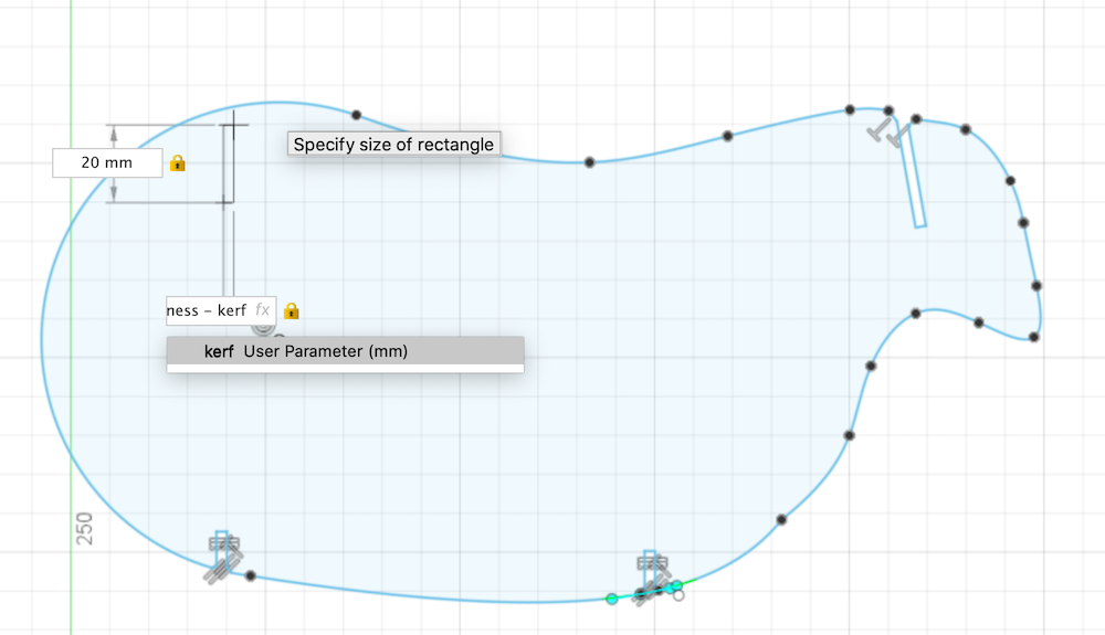
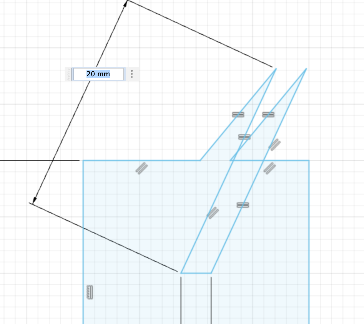
When making the legs of the elephant I was trying to change the parametric but every time I did it the area that I was moving would move in the completely the wrong direction. I then realised I did have the correct constraints on it so I added a lock constraint as you can see below and it worked very well.
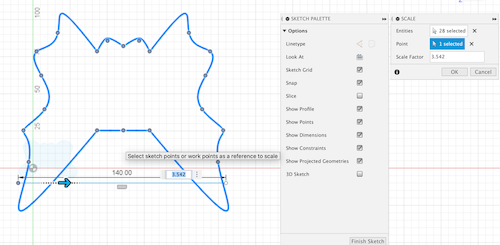
I realised I had made the ears way too small so then tried to scale them up as I had done before last week with my mobile. But when I scaled it up the whole sketch became very distorted and because of the constraints it just didn't work. I ended up scrapping this anyway as a design but thought it was important as is made me in all other sketches to get the measurement correct.
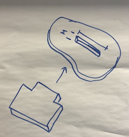
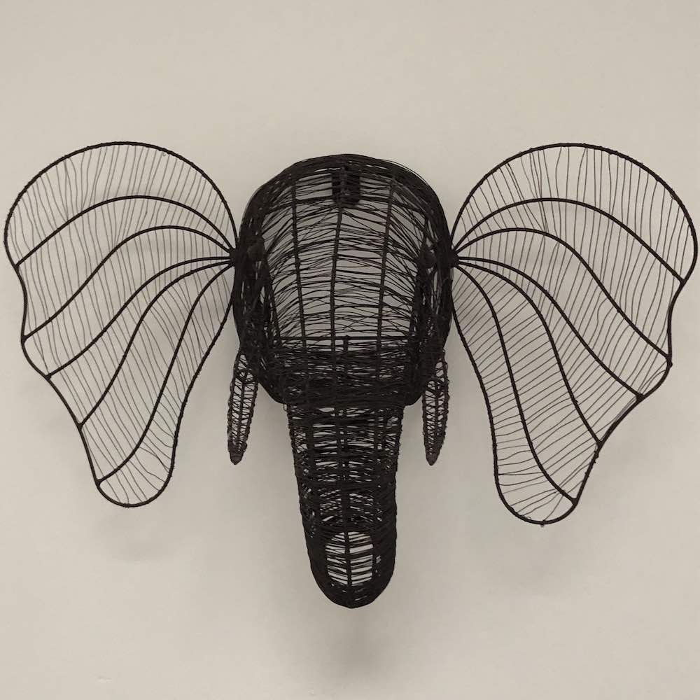
I ended up having the idea as at my house I have an Elephant head made out of wire hung up in our hall way (see image below). This gave me the idea that instead of making the whole body of the elephant I could just make the head with the trunk coming out. So that you can edit the truk rather than the whole piece. This would also make my project easier as I'd have less parts (or so I thought haha).
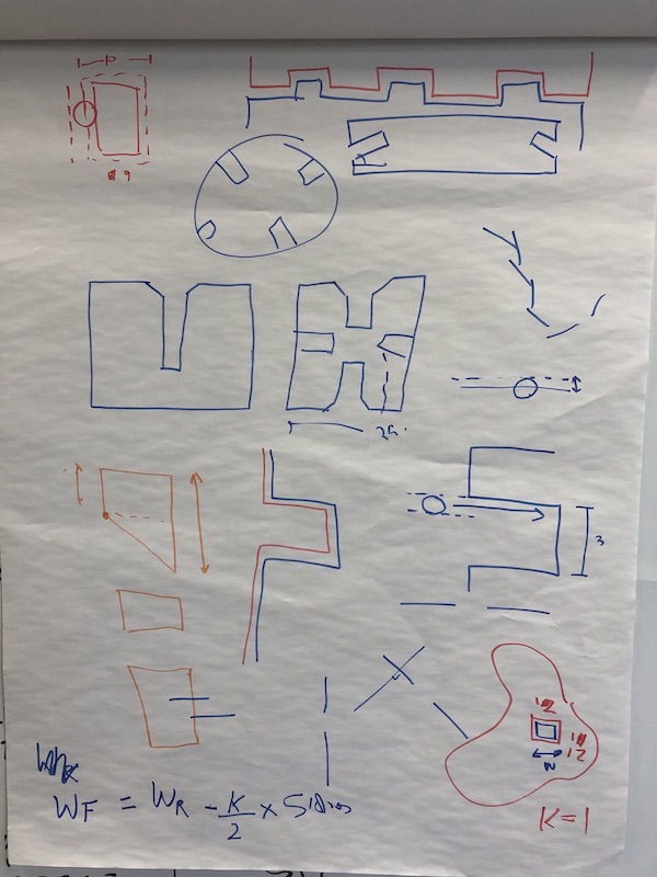
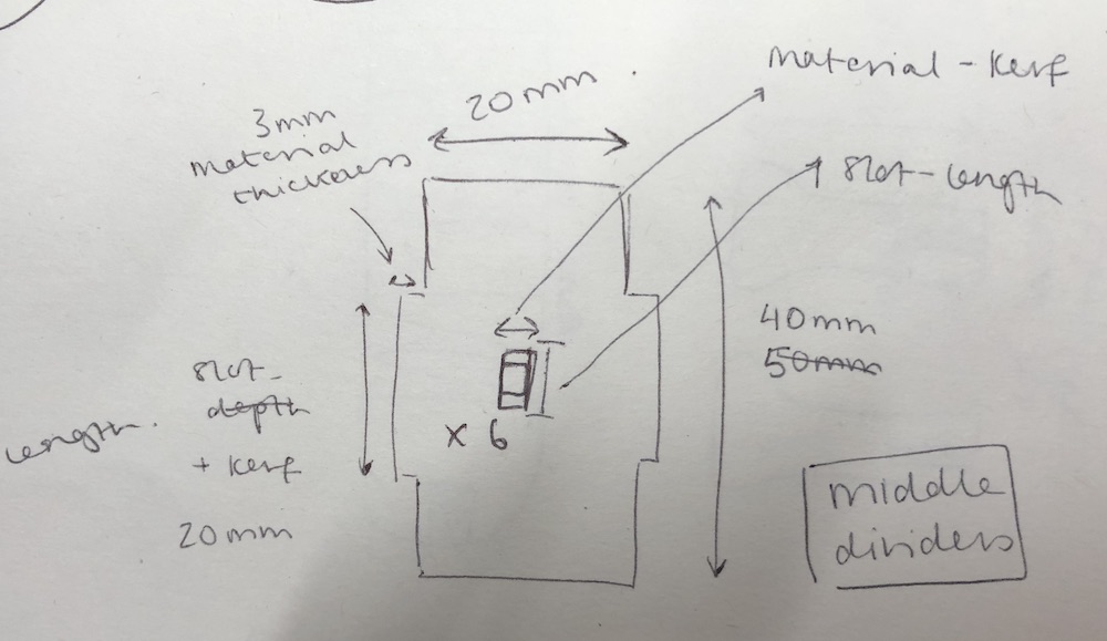
I then started by drawing my ideas in my sketchbook so I could see what the outcome would looking like so how all the pieces would fit together as a 2D sketch. This really did help me under stand what I was doing as before I was still struggling with where to add and where to take away the kerf. This is when I decided to just draw out the joins I would be using so I had my own little cheatsheet. I also added what parametric I had in my table so I could refer to it rather than having to open it up every time.
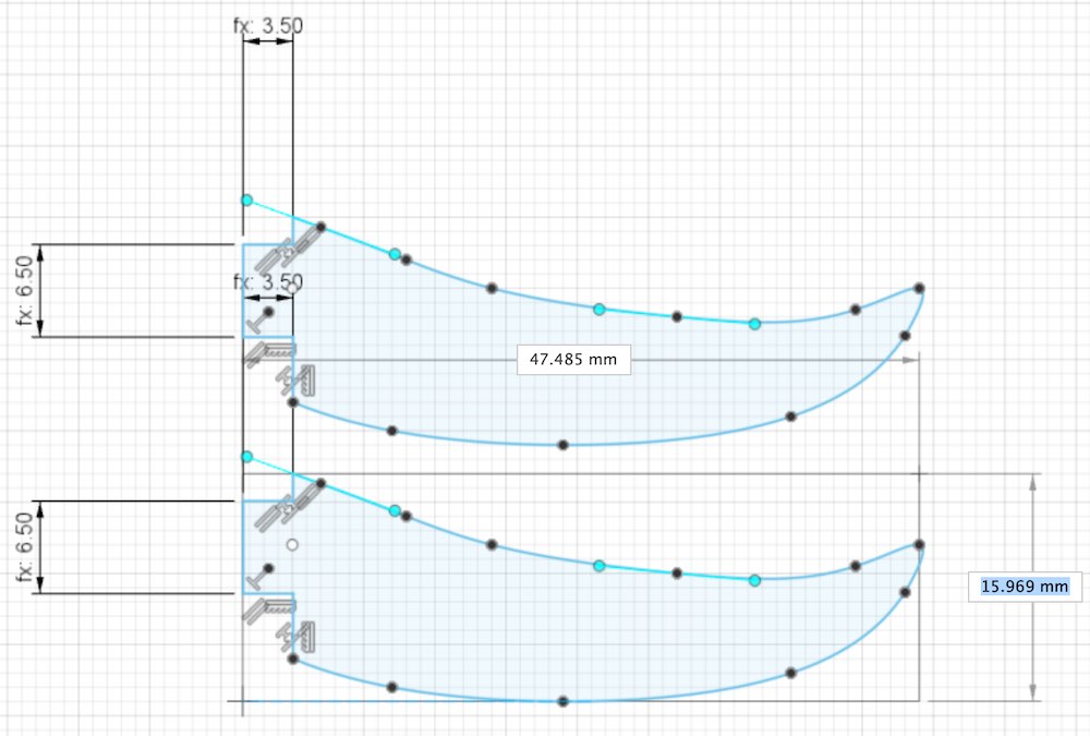
The very first thing I did was start a new document and put in the parametric for these sketches. I used my cheet sheet and put in the numbers I thought would be correct, but of course the best part about this is if I change my mind on a dimension they all change!! I did find it hard to get the correct for the parametric just so I wouldn't get confused each time I typed them into the dimensions. But overall I think I now have this done and I understand all that I have learnt.
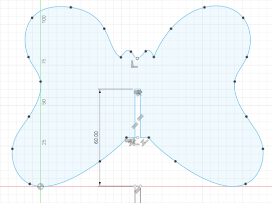
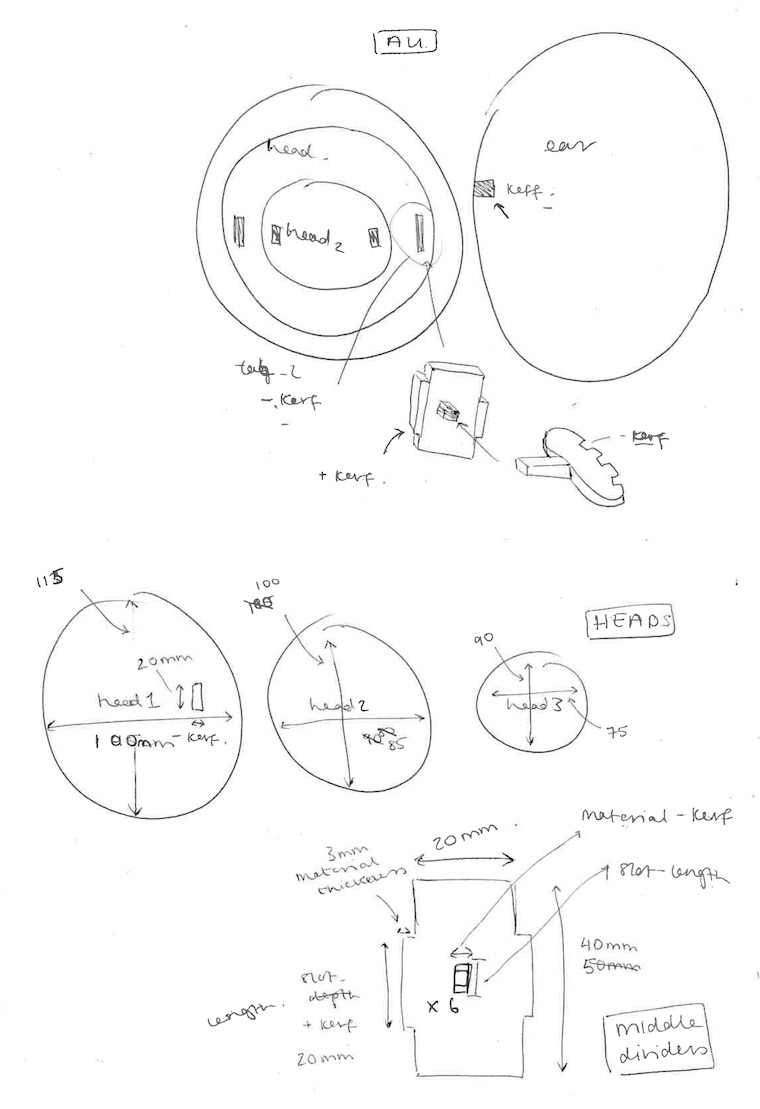
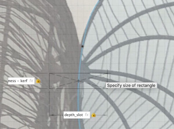
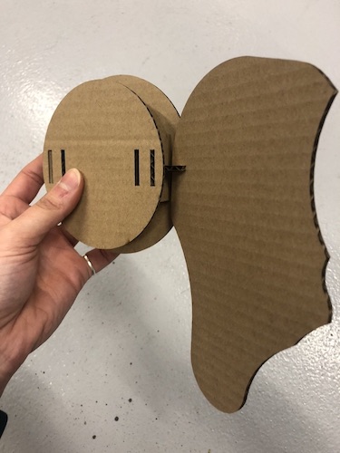
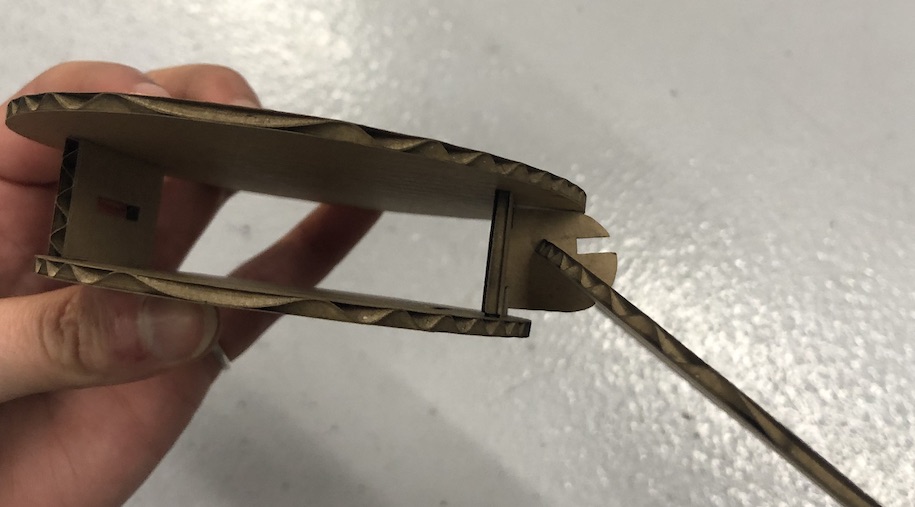
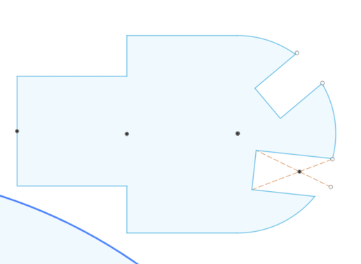
I started by tracing the image of the ears from my photo I took of the elephant on my wall to get the correct shape for ears as mine looked more like a butterfly. I also added in a press fit joint so that the ear would then slot into another part which will also have a press fit (see image).
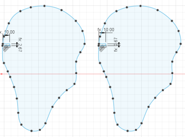
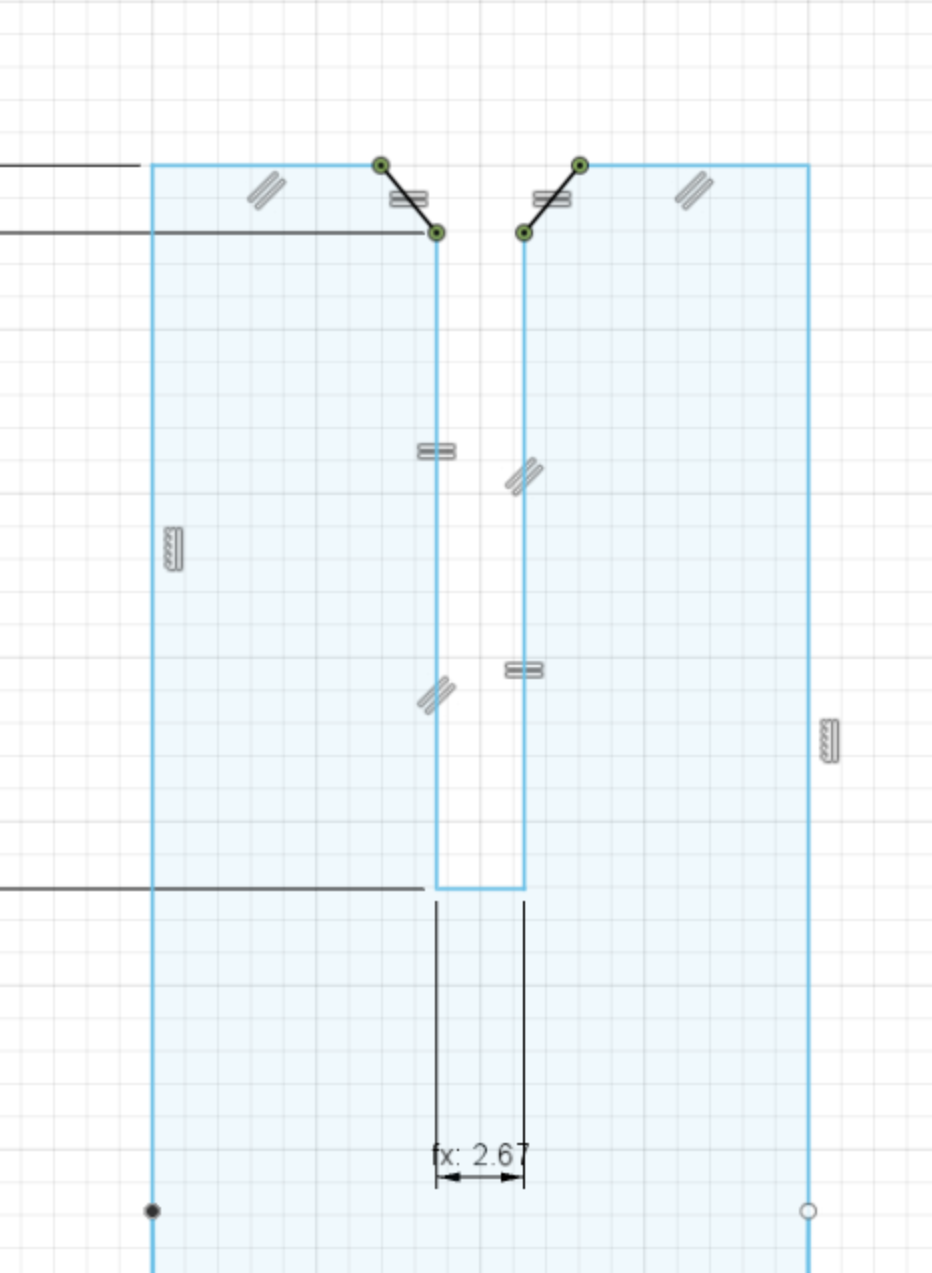
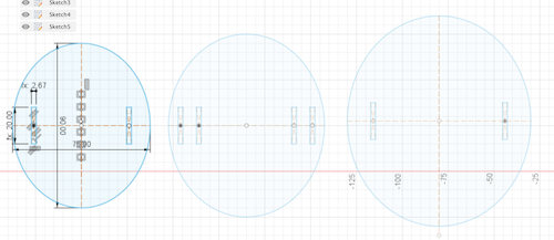
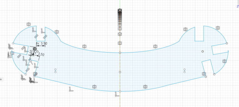
After the ears I moved onto the heads and what they were going to look like and how they are going to lock together. I started by drawing which is of course really helped me understand how it was going to fit together. So in each head there is a slot which a tab is going to be placed so that they can connect together. As you can see on the drawing I even marked down when I would be adding kerf and when I would be taking it away.
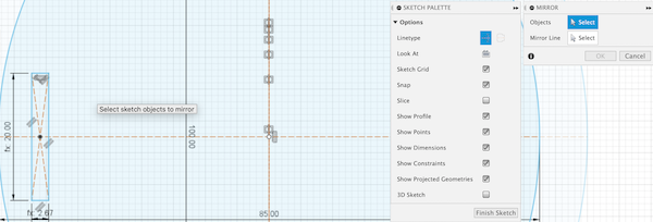
What I also did was when I was marking on the heads where the slots where going to go. I mirrored the slot so that it was equal on both sides of the head. It also meant that whenever I changed the original slot the other one would change too because of the constraints which was very handy!
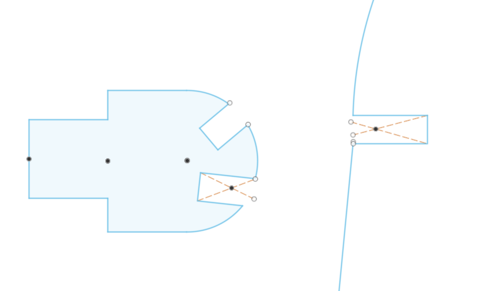
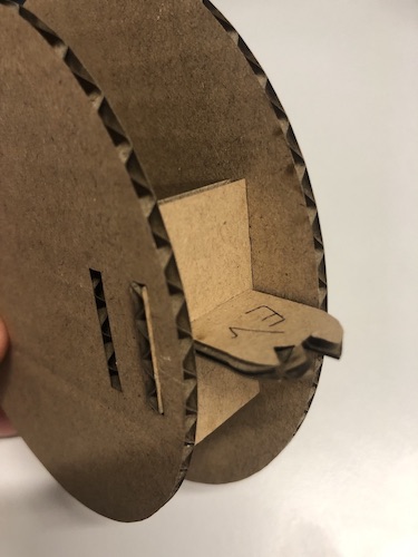
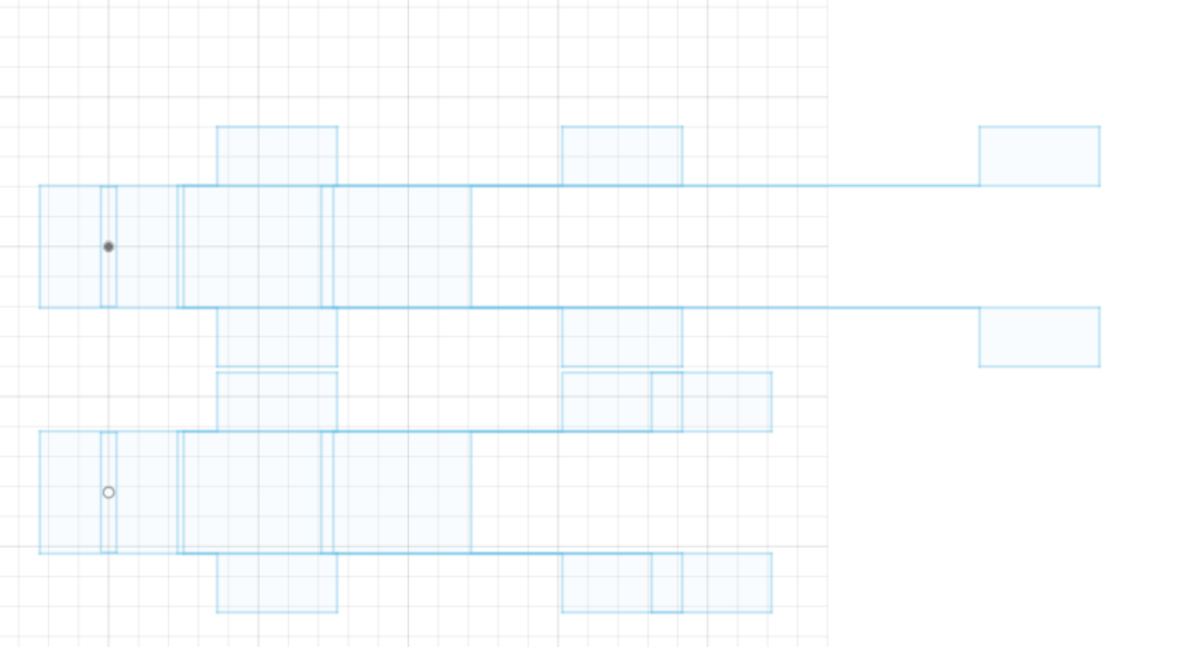
With the middle dividers I drew a box and then added the two tabs on the side. I needed 4 middle dividers, one with a whole and one without. The one with a whole would be connecting the ear to the body so that the ear can be slotted in vertical to the body of the elephant.
I then realised after I had done my first print that I had done the the slot the wrong way so that the ear was going to sitting horizontal to the head which was completely wrong! You'll see I have changed that later in the process and you'll see my first print was very wrong when it came to scale and slots being the wrong was around.
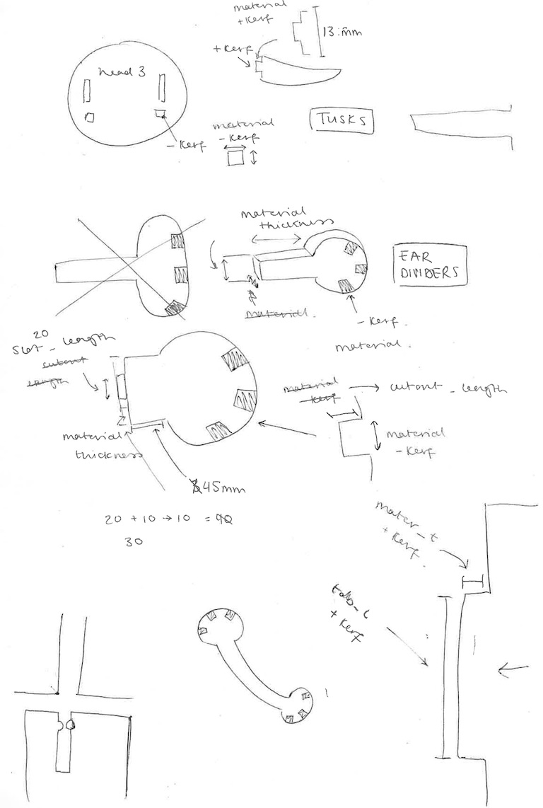
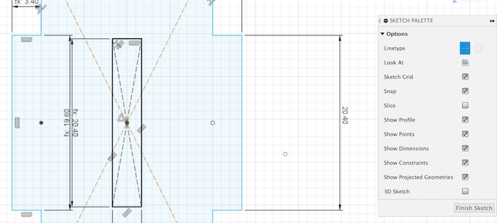
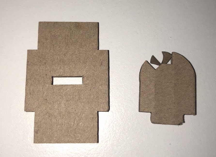
Once I had completed the middle dividers I moved onto the ear dividers (the image above is the final divider) it took me a while to get this one right. I have noticed I struggle with dimensions when it is on a screen. I started by designing what I thought it should look like (see image below - sketch on the right), I then realised that this wouldn't work as the head 1 is flat against it. So I made a new one (see below - sketch on the left) which has a flat edge so that it can slide up against the head.
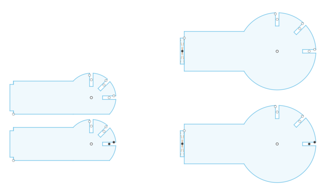
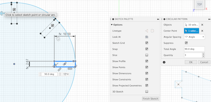
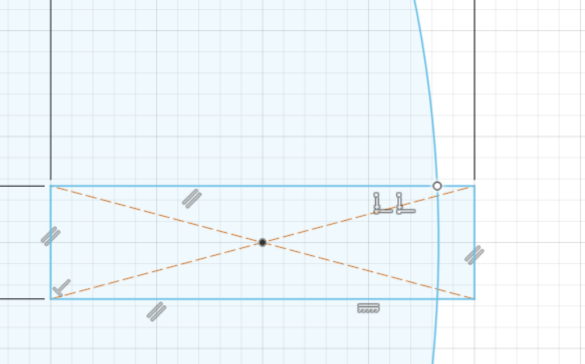
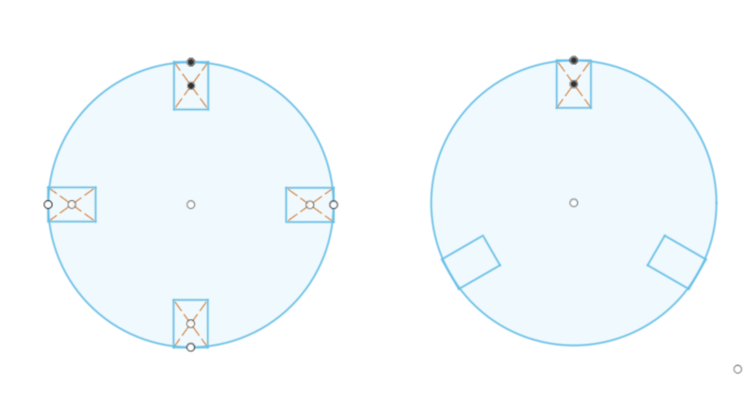
Making the press fit was a very interesting part to this sketch. I had an idea that the ears could be moved forward and backwards so I would just add two press fits in the the divider. To do this I used the circular_pattern tool which meant I could choose the amount and then move them to fit where I wanted them. This did make it harder when I ended up changing the design in the long run as it didn't seem to join the movement I had made.
This is a long process but has to be done to make your work print, and after a while it becomes very simple and just a rythum you get into.
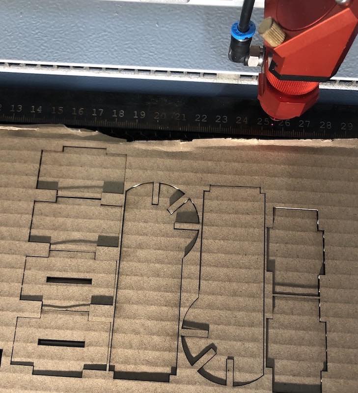
With my first print I was a little cocky and decided to print the three heads, the middle dividers and the ear dividers. Which in the end was the correct decision as I got the majority of it wrong.
I used our Trotec Speedy 300, I really like this laser cutter as it is very quick and accurate.
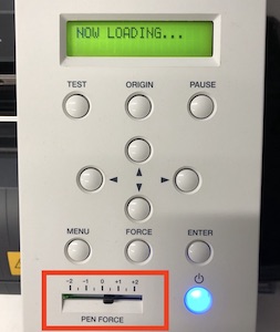
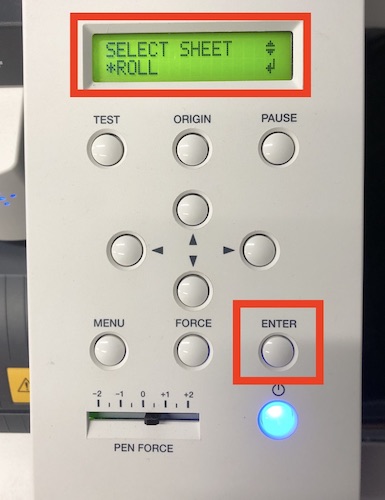
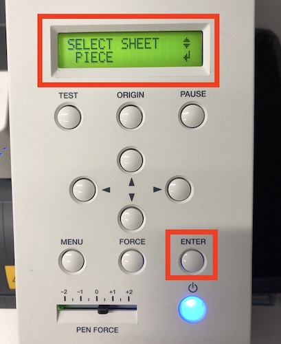
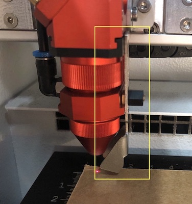
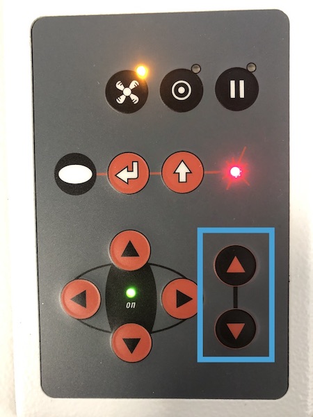
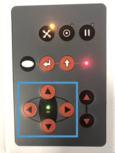
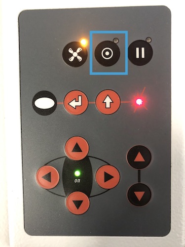
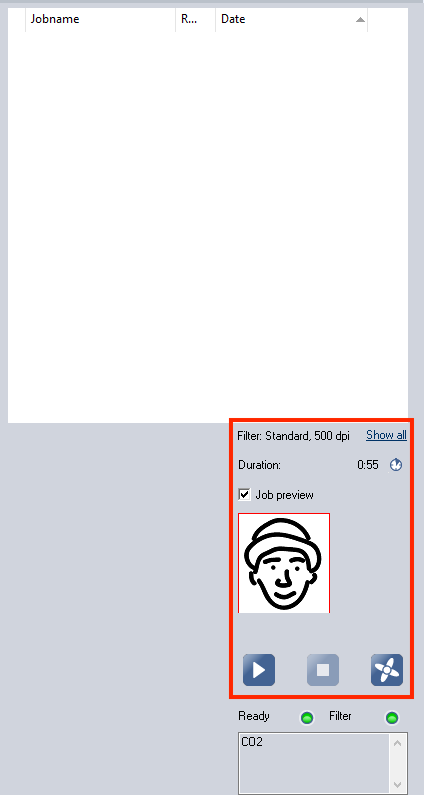
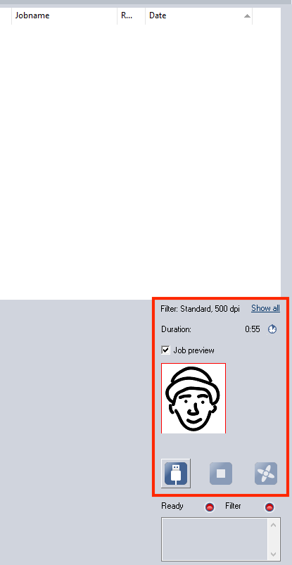
Here is a step by step on how to set up your machine, I have added photos underneath so you can see what arrows I am using when I say this. You already know what the focusing tool is as I have spoken about it above but have attached a photo just so you can see where to place it on the laser.
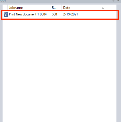
You can choose to set the laser cutter up first or set up your work, this is up to you and wont make any difference to the outcome of your work. I personally like to set up the machine first just I can press play straight away on the computer.

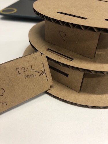
BUT the good news was that my kerf seemed to be correct as my middle dividers did fit into the head slots very well.
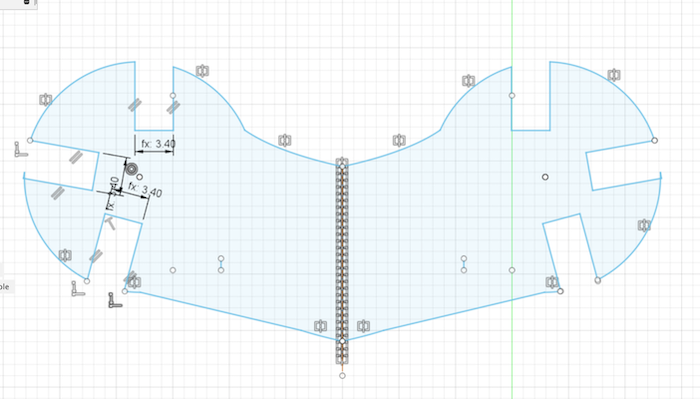
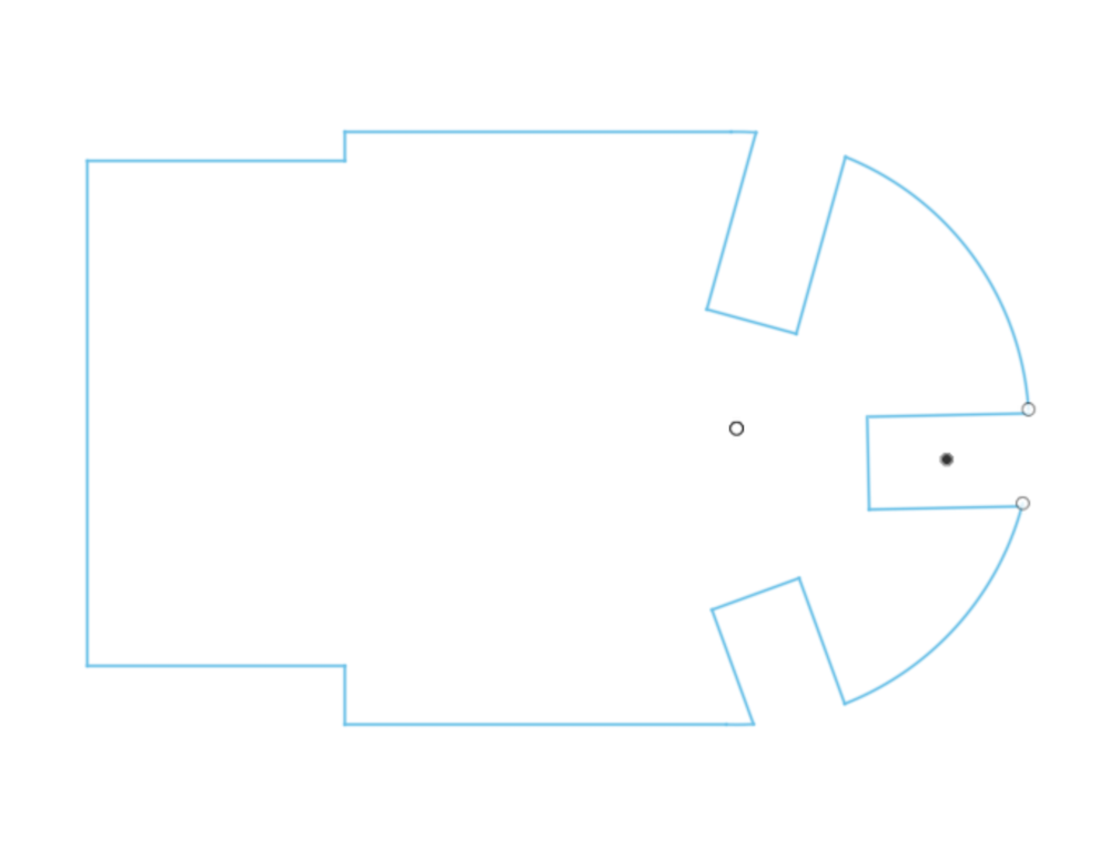
So what I did was change the middle dividers tabs so they were bigger which you can see in the image below. I also as seen in the iamge below, redesigned the whole of the ear divider and put the correct direction on the slot in middle divider. I realised that just by changing the whole ear divider was easier. But as you can see the gab between the who press fits was too small so it just got crushed when pushed together.
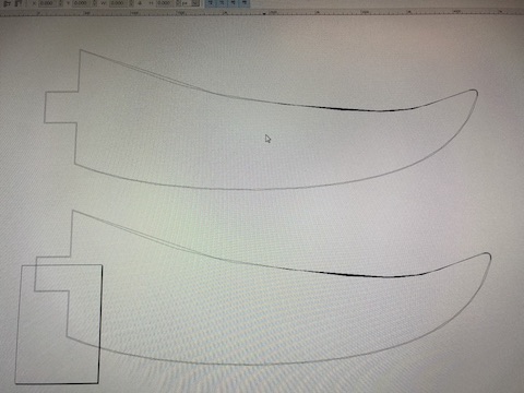
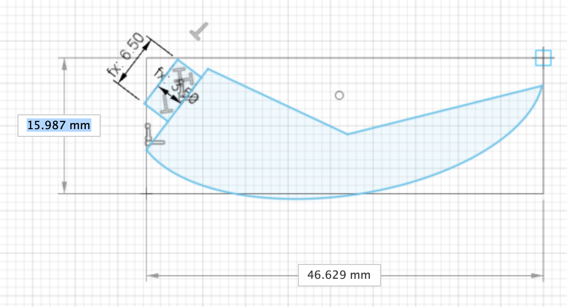
I then moved into the tusks which I draw the same way as the ears with the spline tool. I was very placed with them and then I decided to print them to see if I had gotten the correct measurements right and the angle correct. But when exporting them into inkscape they did not come up the tab did or press fit for ear but the curves did not. So I had to go back to fusion and change the drawing so that it would take the lines I had made.
I did try to import the tusk in illustrator and see my making other alterations if it would work, but sadly it just didn't like it at all. It kept making the line two rather than one which isn't very good when it comes to cutting on a machine as they will just cut both.
With the ear I had the same issue so I went back into fusion and made the whole ear out of many circles and connected them together by just using the line tool. This then worked find when moving it to Inkscape, as i just traced the old image so it looked very similar.
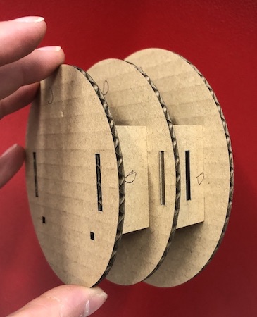
I now went ahead and printed the head 1 and 2, the ears, tusks and all the dividers. This worked well and made me realise that I was getting the hang of it all. Woohoo!!
BUT THEN...
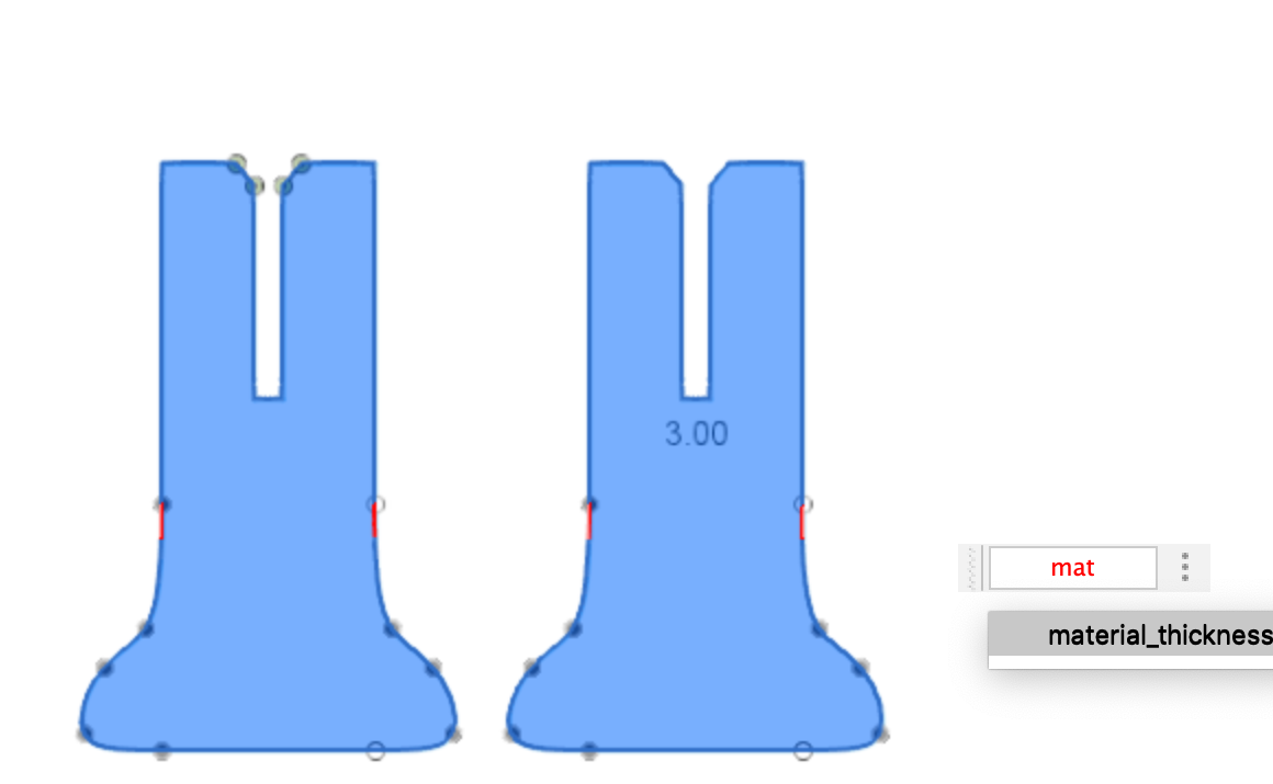
I had the material thickness changed which would be fine as the parametric would help me out there so all I had to do was change the material thickness. But as it was late and I was a little confused I kept changing the kerf measurement rather than the material thickness. This then made everything wrong but I managed to realise I had made a mistake sooner which was good.
When changing the parametric again the dividers did not like it, I then moved back and looked at the constraints that where added and this ended up being enough for me to get the parametric to work again.
With the trunk I had a few ideas with this one and in the end I went for a very simple design but before I got there I tried put a few different ones. The first one which you can see below was a curved piece with two balls on the end with little press fits added so that you can rearrange them in different variations. When I did this though they came out rather chunky and didn't have the right movement I was looking for.
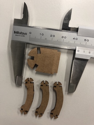
I have realised whilst doing this project I have an issue with scaling on the screen. I seem to do it a lot where I print the item it is just completely off. After this week I am going to buy myself some very fancy callipers and keep them attached to me through out this course!
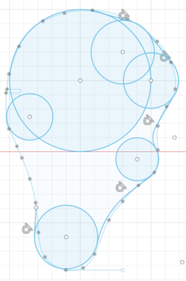
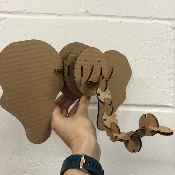
Once I realised that just making circles was the best option to get the trunk moving in the correct flow. I made a circle with three press fits, I made this put them together and then thought that adding another circle with 4 press fits would work better. But when placed together they were too straight so I have now added the two together.
There are 8 circles 4 with 3 press fits cut out and 4 with 4 press fits cut out.
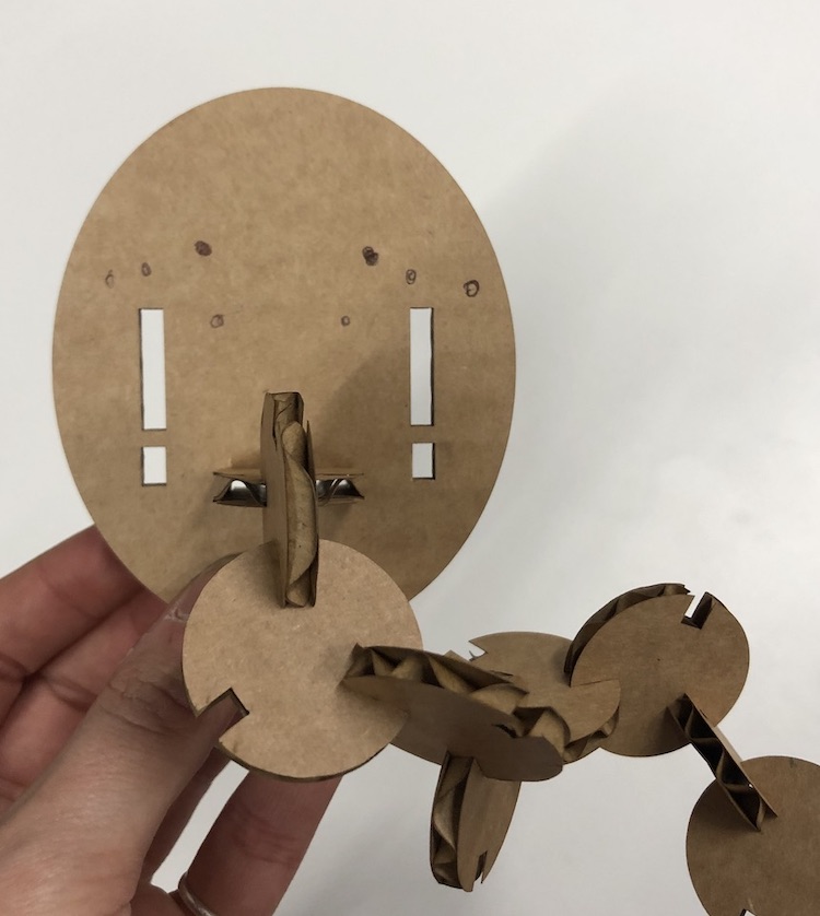
I realised that the dividers for the ear and the trunk their tabs were too short so if I added more weight they might fall out so I just lengthen the tabs so that this wouldn't be an issue. I would also add a whole in them so that if I would make them out of wood, this would be a pin join. I also needed to be aware that when there was weight added to these parts they could very easily bend out because of this I also made sure that when I cut out these pieces they were going against the grain of the cardboard so that it could hold its structure.
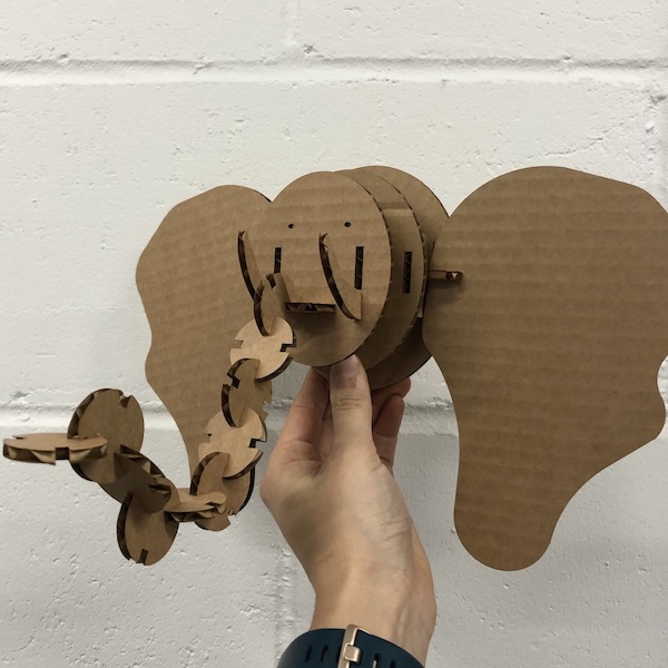
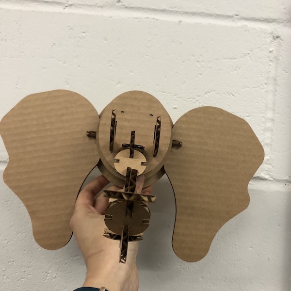
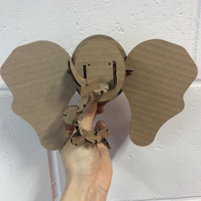
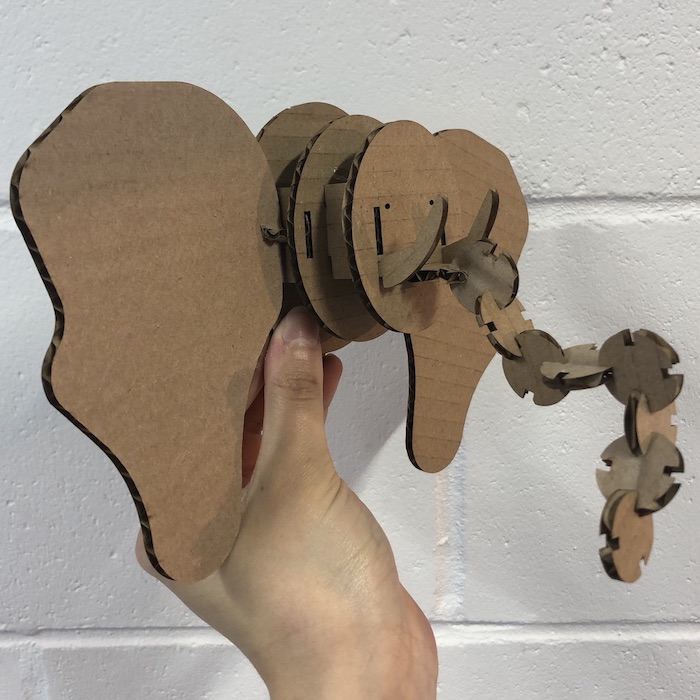
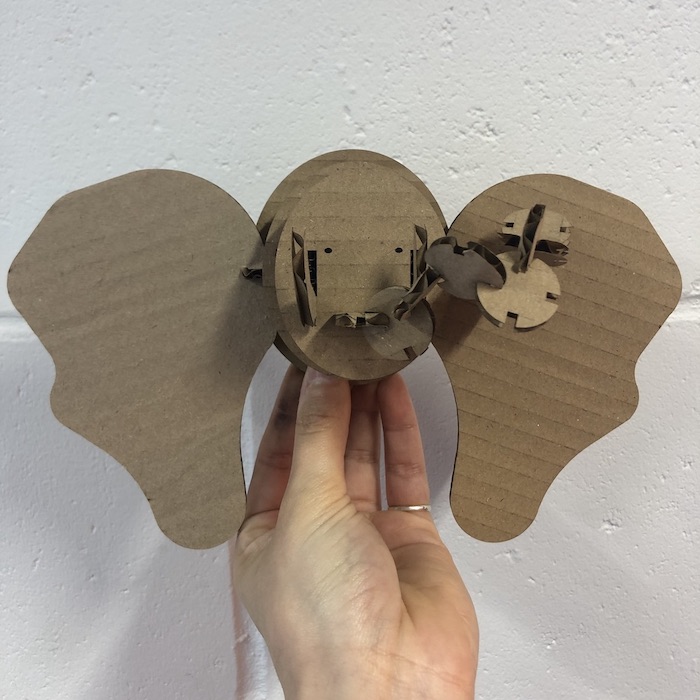
Once I had printed the final piece then I realised it did need eyes as it looked a little creepy. So I drew on the piece to see where the best place was to put the eyes. I also had a look at where their the eyes are on an elephant and they are placed on the side of their face which unfortunately I dont have in my model so I placed them in the place where I thought it worked best. Still not hugely satisfied with the outcome but I can try another placement later on if need be.
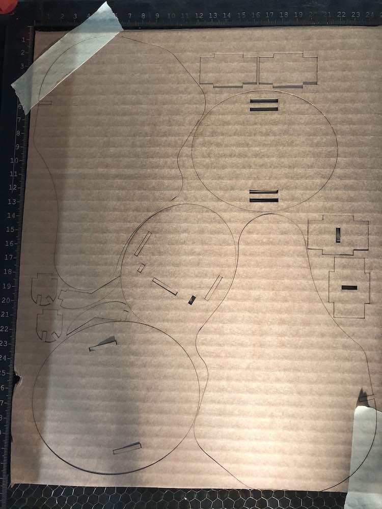
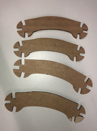
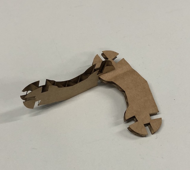
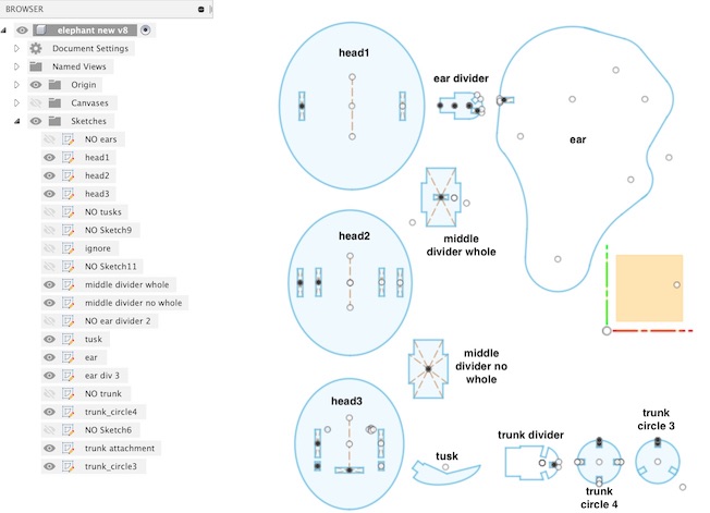
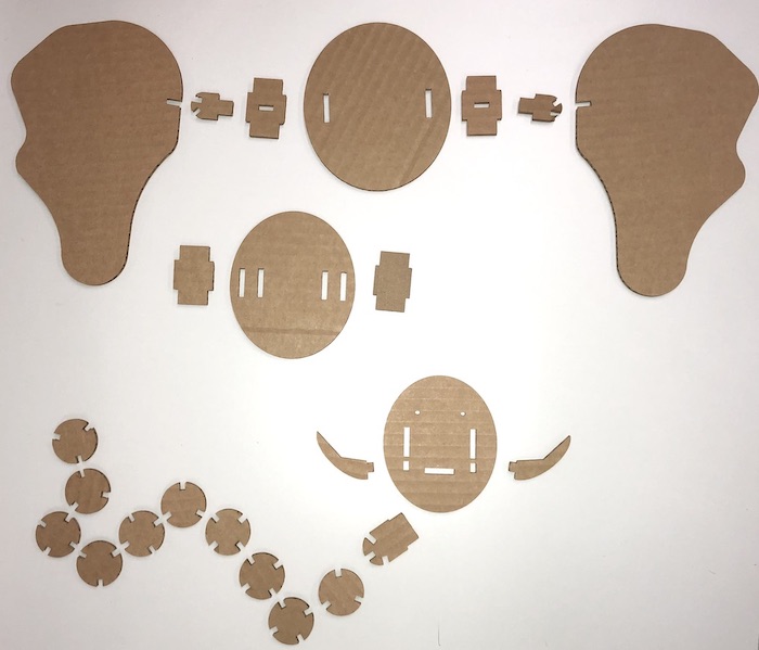
These are the final sketches of my elephant which I printed and put together. As you can see I also separated out the 2D prints of the pieces and laid them out. I really like this part of the process as then seeing them all together is very satisfying.
Overall I think that this week was amazing, I really enjoyed the instant gratification as you made the sketch moved it to Inkscape and then printed it. You could then change the whole sketch in a few seconds and then print again! I would recommend that if you are new to this and don't have much time like me then choose something simple and fun so that you can get the satisfaction quickly. I would also recommend making something becomes an image as I think that made this whole presses much better as I knew my outcome had a look which made it easier to have an end point when you don't have a lot of time.