Hello again everyone, this week I had a little delay (do not hate me), but I have very interesting things to tell you in this chapter, so be prepared that here comes a small tourist guide of what was partly the assignment this week.
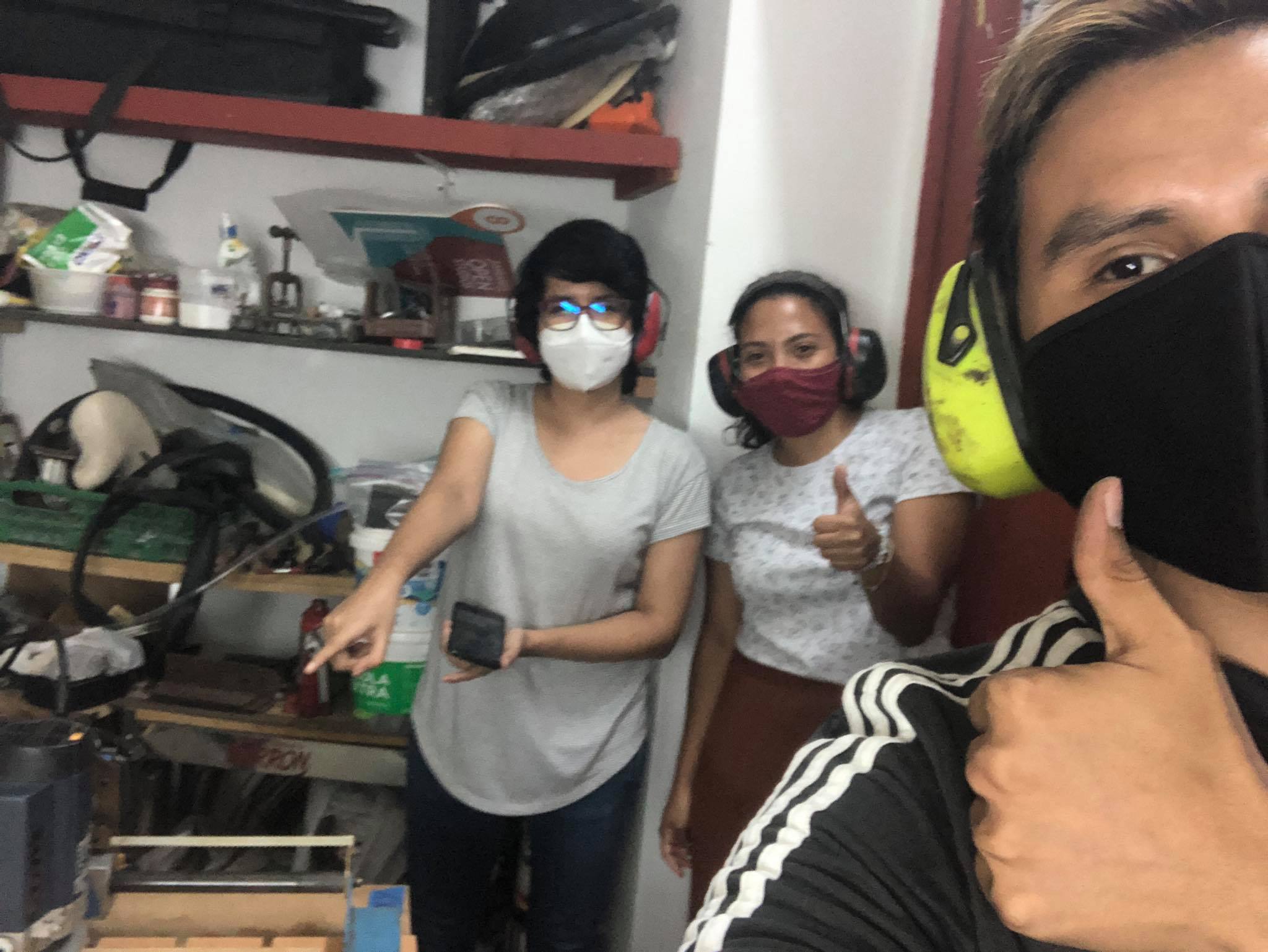
As I told you in previous chapters, Lima is going through a somewhat complicated situation with all this pandemic, however this is not enough reason to stop an entire team with a great desire to achieve objectives, so we left the San Isidro facilities and we went in search of a place that could welcome us (and all the noise we make), that's how the great Stef (Stefany Casanova Gonzales) told us about the possibility of resuscitating an old machine (creation of the great Jorge Lopez) of the century Last time to do this assignment, we didn't hesitate for a second and headed for the FabLab Detonador.
The Detonador workshop (soon Fablab) is the exact definition of what is in essence a Fablab, a cozy place in which anything can be created, this fablab is located in the heart of Barranco, bohemian district of Lima, which is one of the most representative districts in all of Lima.This district houses art even in the air you breathe, it has the largest artistic exhibitions and a wonderful display of street artists who are responsible for giving life to the walls of the Barranco streets .
Probably up to this point they have the doubt about "Who is Jorge Lopez?" , Jorge is (or was, nobody knows) an electronic engineer who had the wonderful idea of creating a CNC machine to support his thesis, so far there is nothing new or novel but the interesting thing is that our dear Jorge did this ago about 20 (year 2000) years approximately (exactly, when you and I were not even planning to be conceived), we are talking about 3 decades when the internet still did not reach Peru in its entirety and talking about CNC machines was a utopia for the first Peruvian companies When I heard that story I immediately went to the heart of the machine to prove or disprove this story and I found this:
The easiest way to see the time this machine had is through its electronic card and I came across a card that had a DB25 parallel port (the ones used by some old printers), this port was no longer used since they came out the first serial communication ports.
Without a doubt, Jorge Lopez knew very well what he was doing and he inherited a great machine from us, so wherever you are,
¡Thank you very much Jorge!
¡Its alive!
To put this machine into operation, it was first necessary to see the state it was in and then calibrate it so that it can do a proper job.The last update of the machine left it as follows:
The drivers that the cnc has placed are the Q2HB44MA, this card is in charge of controlling the rotation of the stepper motor and in turn supplying the necessary current for the work of the axis to which it is connected, it should be noted that this card is only intended to a single axis, that is why 4 of them were needed.
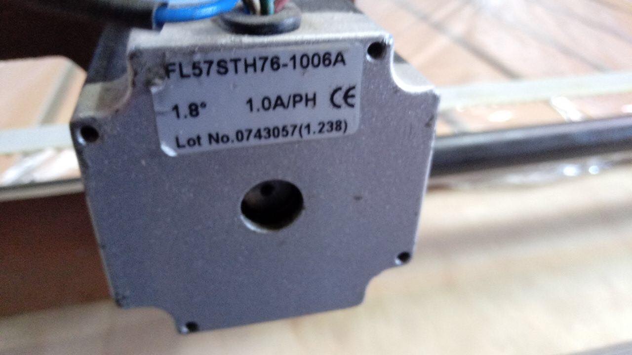
In the part of the actuators we have 4 stepper motors FL57STH76-1006A which gives us a resolution of 1.8 ° per step, which would be approximately 200 steps per 1 mm.
In the power supply we find 2 types of sources (AC and Dc), the DC source is supplied by a 12-volt switching source and the alternate source by 220 Vac, all of these in turn integrated with the help of a CNC shield that they use as communication port to an arduino uno.
Once the drivers have been correctly connected and the motors are powered, it is time to connect it to the PC and start cutting.
¡Time to test!
For the first tests, very basic rhino designs were made and the same programs that were used for the pcb cnc were used, next I will show you the first test that was done to verify that the steps of the motors are correct and that it generates us an exact cut.
Once it was verified that the machine was perfectly calibrated, it was time to make the rhinoceros design for our first true cut, below you can see the steps that were carried out for this first design:
Finally we have the results obtained, which can be seen in the following images:
Group test
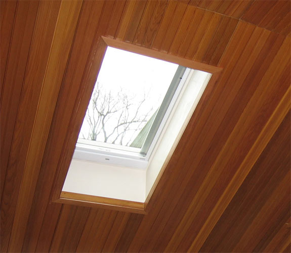
For the group assignment, the operation of the machine was explored and the scopes of the machine were tested with the creation of a 100% skylight for the Fablab Detonador.
The skylight design for the Fablab Detonator was made in rhinoceros and looks like this:
Finally we can see some of the first pieces cut in the CNC:
Individual project
For the individual project I have thought of a piece of furniture that serves as a shelf so that people can place different things, from books to electronic components or many other things. The good thing about this shelf is that we only need flat parts, for this we can do many ways but the best way would be to start with a drawing and then be able to extrude it. At the end of all the steps the result would be the following:
The first step is to fragment the piece of furniture into faces, as you can see this piece of furniture has many repetitive faces, for example we can see the face of the sides and finally the bases of each floor of the shelf and this is accompanied by small divisions to fragment each floor in 2 positions.
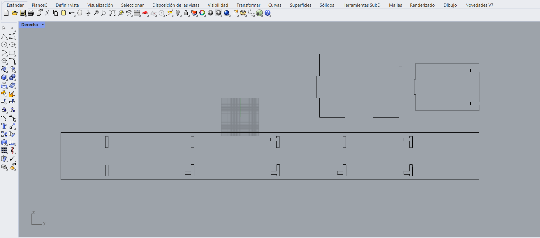
We are going to draw a floor of the shelf since the rest are exactly the same, the reason for drawing this floor is because later we only have to extrude it to generate the 3d design of the base, this will be repeated on all the floors.
For the view on the right, only a 2D design will be made, which will then be completely extruded with the general thickness of the material, in this shelf we have 3 pieces that will be in these positions, the 2 types of separators and the faces that are at the sides.
After extruding the curves, it is time to position the parts to verify the fittings so that they are later assembled without any problem and do not need any additional work when the pieces are cut.
In the end you only have to replicate the pieces and be able to fit the parts and we will have a result like this, you can download the design from the link at the bottom of this page.
For the cut, the Vcarve or Aspire program will be used, either of the two are compatible with the results we want to achieve, the configuration is very friendly, that is why said program will be used, however many times these programs are found in versions with prior payment and only its free version is used.
Let us always remember that we must make small calibrations so that the machine can know exactly where the thickness of the material begins and ends, for this we do it in a very simple way, placing a metal contact and lowering it very slowly until it can close circuit with the signal that is injected to the bit.
Finally, it is time to place the wood so that it can be cut on the machine. This wooden plate is 50 mm, so it is easy to handle. When cutting, you have to be careful with the use of the machine and You always have to be accompanied by the person in charge of the laboratory to be able to help us from this person.
The pieces came out correctly cut and it is time to place more wooden plates to finally assemble the shelf.
Finally, the shelf looks like this, in the end some small modifications had to be made so that they fit together due to the margin of error, but it was easily resolved by sanding down the fit of the pieces a little, in the end we have this result.
To calculate the cuts, different tools were used, many of which were already ready at the time of making the cut, but if we wanted to make a more precise cut and you know what the configuration parameters of each of them are, I would recommend using these tools. which will help us to be able to get the values of the cut made again.
On the side of the program that we will use to make the cuts, we also have this type of tools to do different types of jobs, such as leveling jobs, internal cuts, external cuts, making low-relief engravings, etc.
First we must start with the cutting tool that we use, the cut was made with the following cutting tool, in some cases more than one pass had to be made to avoid some problems in the cuts.
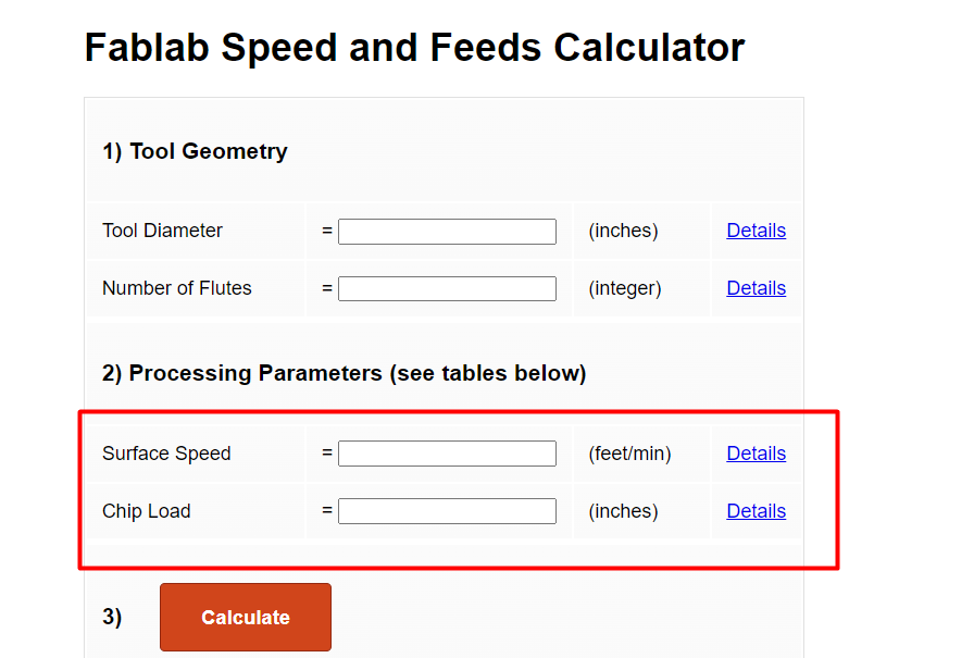
Now that we know what tool we are going to work with, we can calculate some additional values for the cutting configuration, however there are some values that are not a bit clear in the program, such as the chip load or the trajectory speed.
However, the good thing about this tool is that it allows you to visualize the meaning and importance of each of these values, as you can see in the image, it even describes the possible values of the parameter to be edited.
On the other hand, it also allows us to calculate the cutting speed of the cutter in different materials, this tool has a table in which we can obtain the approximate recommended value for each of the materials that we could use, in our case it is mdf wood, so We already have that parameter ready to be able to calculate the others.
Now that we have all the previously commented values, we can calculate the most important ones to upload them to our cutting program.
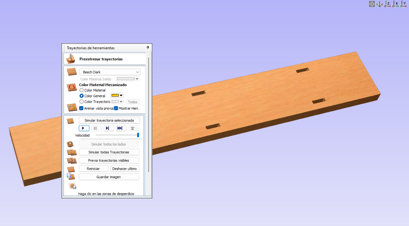
Once all the parameters have been entered, we can have our file ready to send it to be cut, the program also allows us to see a preview of how our piece would look with the cuts made.