This week I have had a sudden lack of inspiration to write and it is that do not believe that all this nonsense that I write week after week comes out of my mind at random (some if), I must admit that when the academy began I thought that the most boring thing would be to write (I hate writing and I think they have already noticed it) but it is the opposite, I love writing to them and imagining their faces when reading all these things and that you think "this guy is on drugs" (I clarify that all these lines I do not write under the effect of any narcotic), but life goes on and does not wait for you to wake up wanting to write and it is something I learned throughout my life, so here I am 6 hours away from the presentation of week 6 and the desire writing just appeared, anyway I could see myself writing at dawn, this was a chronicle of an announced late night.
Due to the shortage of components and the high prices, I decided to immerse myself in the streets of downtown Lima to find the components on my own, here I tell you that it was very nice to walk through these streets again and appreciate how beautiful Lima is despite the pandemic.
Although the dish from week 4 was enough to cover this week's mission, Hayashi had the great idea of making a completely new circuit for this occasion, so the final product will be something similar to the following:
The dish this week will be a programmer oriented in an attiny85 that will have 3 LEDs (blue, green, red) and a reset button for our microcontroller, all this circuit will be able to be programmed through a USB A female port.
PS: The images are completely referential and do not reflect the final product.
The last recipe was a success, so we will keep the formula and components but with a special touch for this week. We have the following ingredients:
As you can see, this time I have set the reference prices, which are prices from Peru but you could find them cheaper if you import them wholesale.
PS: If you want to know a little more about these ingredients, you can visit the first part of “Let's cook a PCB”.
Chef's Notes:
-Don't be afraid to replace components, the best way to play with these values is by knowing the function of each one.
Preparation
The preparation is slightly different from the previous one but just as efficient, for this you must follow the following steps:
a) Step1:
As I always tell you, the prototype circuit is very important but since the base was already tested 2 weeks ago, we will proceed with the electronic design in easyeda and for this you can use the following video:
The circuit that is carried out in the previous video is the following:
Finally, the final result should look similar to the following image in which we can see the location of the components used.
Chef's Notes:
-On some occasions the easyeda autorouter (local or online) tends to present failures or delays, if that is your case you can perform the tracks manually (it is somewhat complicated but not impossible).
-Consider if possible to give a greater thickness to the tracks whenever possible, it will help you a lot when welding.
-Prevents the tracks of the circuit passing through the middle of the pads of a component (as seen in the figure).
b) Step 2:
The funniest and most exhausting part of all the electronic board creation assignments is coming, it's time to send our Gerber format to Flatcam and then send it to the CNCjs.
After generating the Gerber, it is necessary to take it to Flatcam so that it gives us the Gcode for the CNCjs, we can see the Gerber open in our Flatcam file.
To obtain the G code of the tracks of our circuit it is necessary to configure the cut parameters, you can take the following parameters as a reference to make yours:
As a final result we will have our G code and a preview of the path that the cutter will make on our copper plate.
Chef's Notes:
-Eye with the overlap for each route, it is recommended that these be approximately 33% if we use 0.1 diameter drills, otherwise we could generate unwanted results like the one in the following image:
-Flatcam settings vary according to many factors (type of bit, thickness of the cutter, thickness of the tracks, etc), so always explore your own parameters.
c)Step 3 :
Por último nos toca el mecanizado, para ello utilizaremos el programa CNCjs y mandaremos nuestro archivo Gcode generado en flatcam.
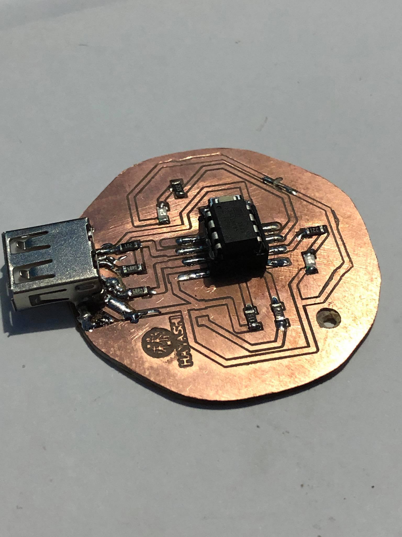
Final product:
d) Step 4:
The time has come to test your patience, it is time to solder the components to our board. Welding is one of the tasks that needs more precision and in the following images you will see some very important data that will help you to do it.
-First you must test their continuity track by track with the help of a multimeter, this will help us find possible shorts or incomplete tracks.
-Start with the easiest components (resistors), when you finish soldering a component you must test continuity between the tracks to see if this last solder generates any change or short circuit.
-When welding an LED make sure it is in the correct position, for this you can use the continuity function of the multimeter and verify that it turns on.
-Finally our patience will be rewarded with a very well welded electronic card and zero short circuits.
Chef's Notes
-CNCs can sometimes have faults which you can repair with the help of a knife or with welding paths.
¡Its alive!
It is time to program it, for this you can check the following link to know how to upload the bootloader and install the drivers. A sequence of lights was programmed that starts only by pressing the button on our board.
Group Assignment
The group assignment was full of challenges, to begin with the only measuring instrument we had at hand was a multimeter, but the most curious solutions are born when you have everything against you, none of this could be carried out without the wonderful equipment that I have, thanks to Mayña (Mayra Ascencio) and Stef (Stefany Casanova) for supporting me in these crazy ideas that occur to me.
La exploración comenzó con un osciloscopio analogico Tektronix 2225.
However we did not get to explore it in its entirety, but we will still explore it in the next assignments
a) Oscilloscope with Arduino:
-This was one of the funniest group assignments because we realized how versatile an arduino can be and the thousands of functions it allows us to use. For this assignment you only need one arduino (it can be any arduino).
-This oscilloscope could be made thanks to a function that the arduino IDE has called serial plotter which allows us to see the graph of any signal that we designate, the signal that we will use will be that of our analog inputs of our Arduino Uno.
-If you want to see step by step how to create your own oscilloscope, you can check the following video:
Chef's Notes:
-The Arduino serial plotter allows you to display more than one signal, you only need to add a separator for each “Serial.println”.
    void setup() {
    Serial.begin(9600)
    }

    void loop() {
    int sensor = analogRead(A0);
    int sensor1 = analogRead(A1);
    int sensor2 = analogRead(A2);
    Serial.print(sensor);
    Serial.print(",");
    Serial.print(sensor1);
    Serial.print(",");
    Serial.println(sensor2);
   delay(1) ;
   }


 -Flatcam settings vary according to many factors (type of bit, thickness of the cutter, thickness of the tracks, etc), so always explore your own parameters.