Hello everyone again, here you have me again writing for you and this time I come to tell you about an important part of my life but first I want you to see something.
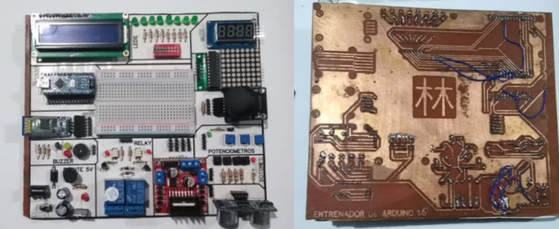
What you saw in the previous video is Fabino, Fabino is a modular electronic system aimed at learning arduino for children from 5 years old, but beyond what Fabino can technically be, for me it was a full stop in my life. Has that moment ever come in your life where you doubt everything you know or are capable of? For me, 2019 was that year in which everything was uncertain, Fabino was born as a challenge that I did with the aim of doing something great that not only helps me but also all the people who want to learn in a more friendly way And it was thus that on April 08, 2019, the first Fabino prototype was born.
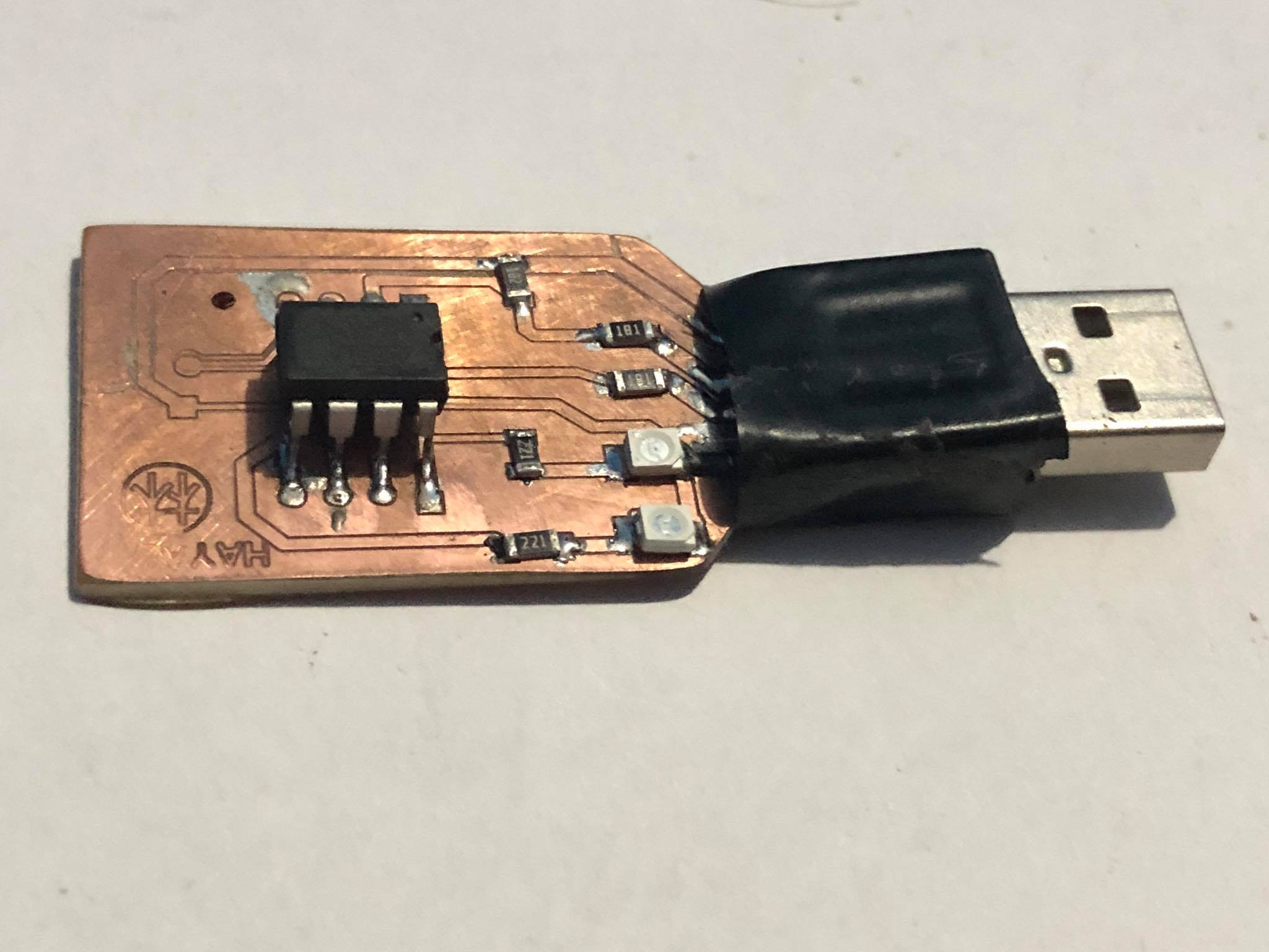
The first plate was made completely by hand (with many errors but working), from that moment on Fabino has not stopped and has been improving for you.
Before I thought that I was the one who discovered and invented Fabino, but now I know that he discovered me, thanks Fabino ❤️
For this mission it is very important to know how to choose the ideal microcontroller to develop the different missions that are proposed, first the most important thing is to explore the microcontrollers available in the local market, after a few laps in Paruro, I determined that almost 80% of the available microcontrollers were variations of the attiny85 and the atmega328, both well-known microcontrollers and accessible not only to purchase but also to program.
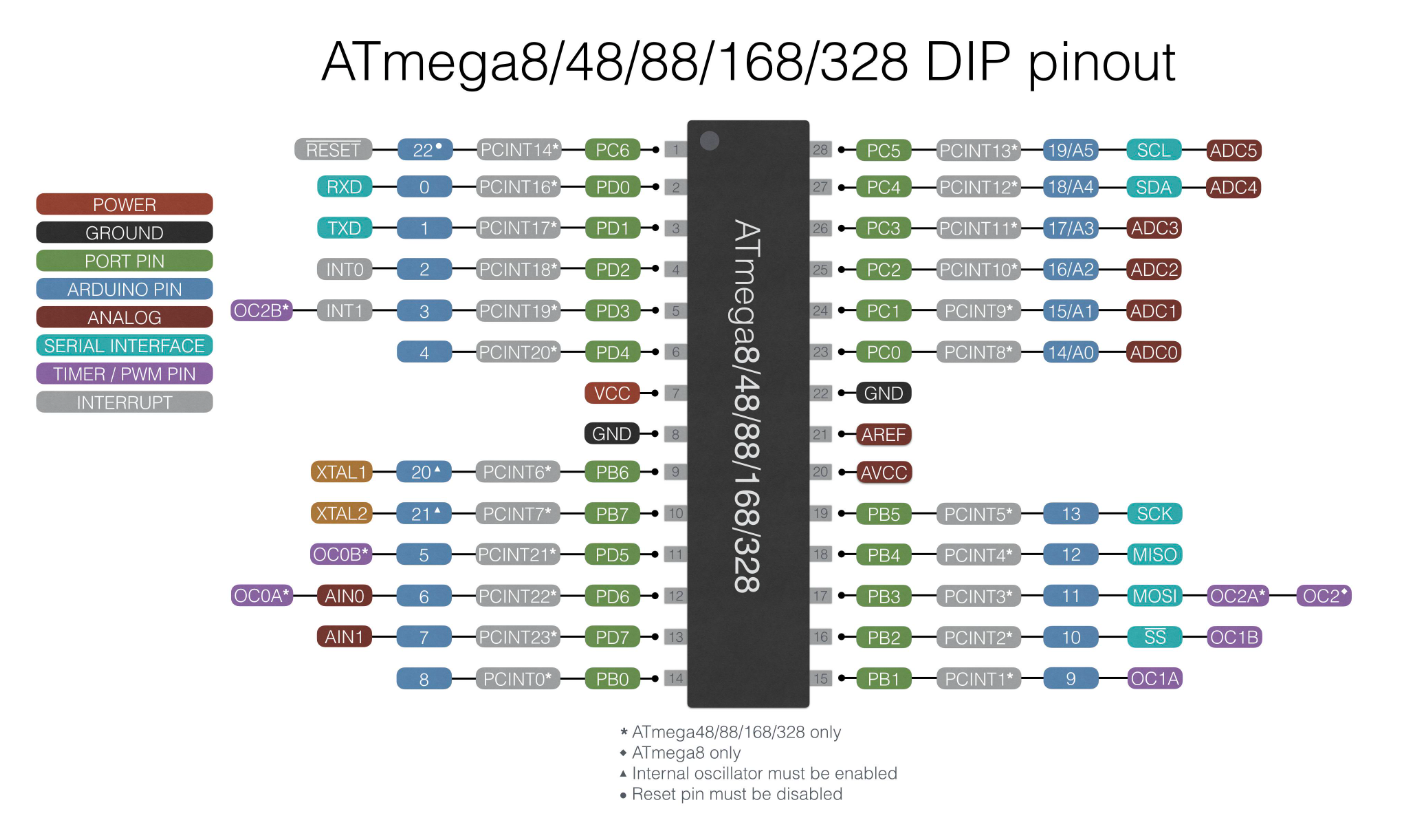
First we are going to observe the most famous microcontroller locally and it is called atmega328, its recognition is due to the fact that it is the microcontroller used by the arduino uno, nano, micro and among others. On the other hand, its programming method is also very direct and it does not need programmers but directly through the icsp protocol, however, as we can see in the image, it has many more input and output pins and other similar characteristics.
On the other hand, the circuit to be able to start this microcontroller requires a greater number of passive and active components such as resistors, crystals, diodes and among others. As we can see in the image, this is the necessary circuit to be able to use our card for the first time.
That is why the microcontroller that we will use is the attiny85 since this allows us to work as a bridge for the following works and we could also program them directly.
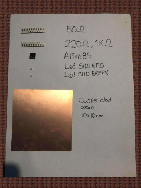
For this programmer we will need the following ingredients:
a)Resistors
The resistors are a very important component, especially those that are connected (R1 and R2) directly to the data bus (D +, D-) of 50 ohms (this value can vary between 50 to 100 ohms approx) these guarantee continuity serial transmission between our PC and the microcontroller, on the other hand we have the resistors found in the LEDs (Power and D1). Remember that the main function of a resistor is to oppose the passage of current, therefore it serves as a protector in the case of LEDs and in the case of the data bus as a voltage divider to guarantee a voltage threshold.
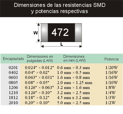
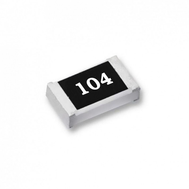
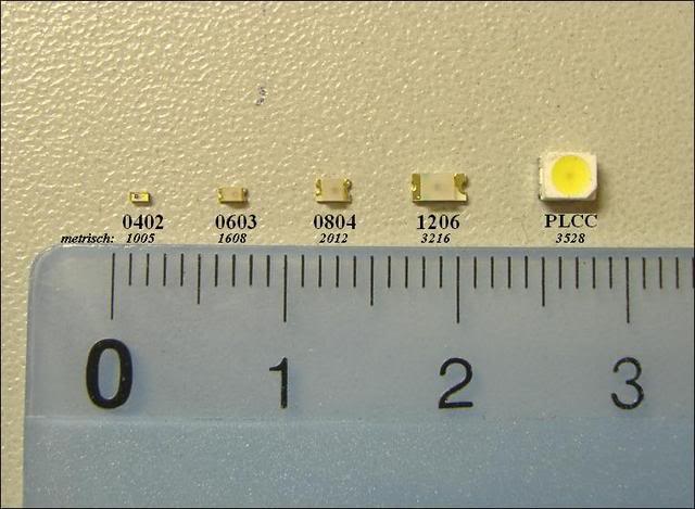
The resistors that we will use are SMD (Surface mount device) resistors, since they have reduced dimensions and this will also help to avoid parasitic currents (smaller contact area on the board = less noise). The resistor packaging that we are using is 1206 because they were the only ones that were achieved.
SMD resistors have different types of packaging and this is due to the dimensions they have, this is reflected in the following image:
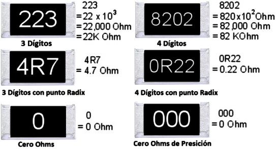
These resistors also have a very particular way of finding the values (ohms) they have, unlike the others that have a color code, they have a numerical code that can be interpreted as follows:
As you can see, the last digit of each resistor is a power of 10 that must be multiplied by the preceding digits. Based on the above, do you dare to calculate what the value of the next resistor would be? .
Chef's Notes:
-Did you know that there are 0 ohm resistors?
Imagine 2 cities separated by a river, the only way to connect would be above it, right? , the 0 ohm resistors fulfill the same function, they are bridges between 2 copper tracks that are separated by another copper track.
-Do you need help calculating values in SMD resistors? Click here.
b)Led
LED is a light emitting diode, whose main function is to allow the passage of electric current in only one direction and to emit a light when the current passes. In our circuit we will use it with signals and we will have 2:
-Red power LED: This LED is connected directly to a resistance, 5V and GND of the microcontroller. Its function is to show us that our electronic board is well powered.
-Green LED: This LED is connected to pin number 5 of our microcontrollers and will basically serve as a test before a first programming that is done in our programmer (like the popular Blynk).
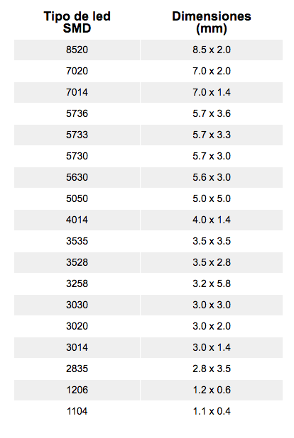
In our case, the 3528 package will be used, which has dimensions 3.5 x 2.8 mm.
c)Microcontroller
And like a meat on the grill or a good sole in the ceviche, we have our main actor here (apart from the chef), the attiny85 is a microcontroller from the 8-bit AVR series from Atmel (here we can also find his brothers ATtiny25 / V / ATtiny45 / V) This microcontroller was chosen for its practicality at the time of being prototyped and for the minimum number of components you need to build a programmer circuit with it (as you can see in the image below).
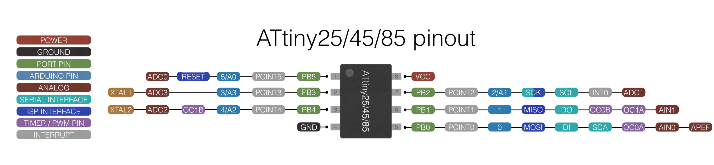
The Attiny85 has a minimum number of pins (legs), however they all share more than one function that can be activated through lines of code, these are the functions of its pins:
All these references regarding the attiny can be found in its datasheet
Finally, this attiny was chosen among many because it is compatible with the arduino software (arduino IDE) and will serve us later for other projects, thanks to its friendly interface.
Chef's Notes:
-Microcontrollers are a fundamental part of a programmer, therefore I recommend that you research a lot about them before acquiring one and above all that you use those that you can find replacement in electronic stores in your country.
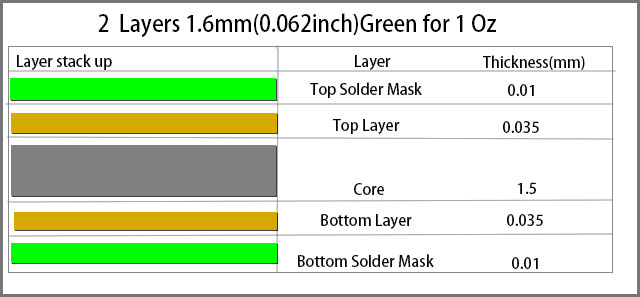
d)Copper clad board
To finish naming our ingredients we have the base of everything, which will support all the aforementioned components, so it is very important that it is resistant and made of a good material. On this occasion, the stock of the local market is used, which did not give the only option to phenolic plates covered with a copper sheet, which is not a bad option but they do have a very limited copper layer as can be appreciate in the following image:
Individual assignment
First of all, we must understand some things about this fabulous microcontroller, one of its most important characteristics is that unlike its older brother, the atmega328, it has the possibility of being its own programmer, which is why it does not need a communicator. serial like a ch340 would be, on the other hand unfortunately as it comes from the factory, it cannot be recognized by our programmer, we have to disguise it, we have to tell our arduino that it is a known board, this known board is called Digispark.
*You can see more about this electronic card here.
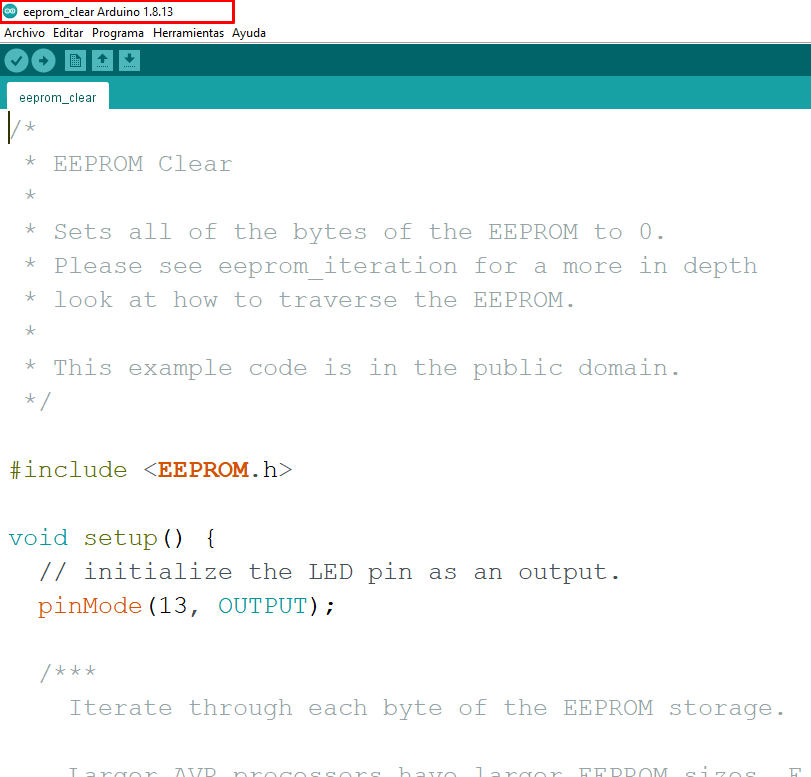
Before continuing, I want to show you a very important program that will help us in all the following steps that we will have to do, exactly it is the arduino ide.
*You can see more about this program and download it here.
To better understand our arduino ide program, we have to know that it has 3 fundamental parts:
-Void Setup: in this section we will have to place all the coding in terms of module configuration, since it will only be executed once. We can also add actions or final instructions that we want to be executed only once, such as a message welcome for example.
-Void Loop: The main program will be placed here, because in this section everything is executed indefinitely, since it is kept in a loop. For example, the sequence of a traffic light made with Arduino could be placed here.
-Global: In this section you can place new sections with new functions or also global variables, for example if we have a sequence of lights that will always be repeated, we can put a name to the whole sequence and call it to the main program if we previously declared that sequence in a Void section.
At this point if you did not have an aneurysm or a mental collapse consider yourself lucky, but calm down I promise that these will be the last steps:
Attiny85 bootloader
-I know it looks beautiful but it still needs to bring it to life, remember that even the Attiny85 doesn't know it's an arduino, but don't worry, we'll give you the news.
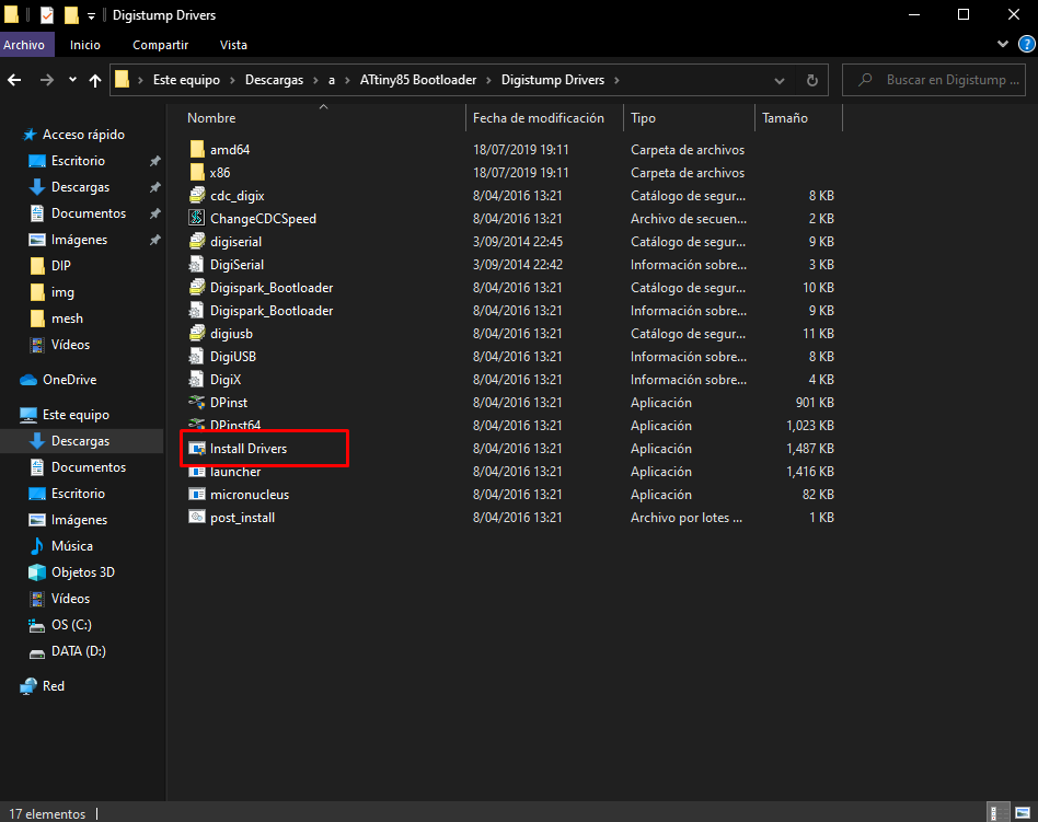
-First we must download the necessary drivers here,which we will install on our pc.
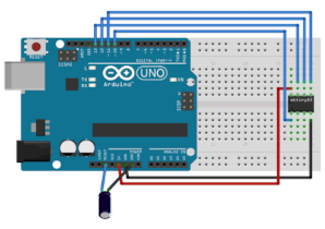
-Once ready you must use another arduino (arduino uno or nano) to be able to load the bootloader to the attiny 85, once our arduino is connected we must load the Arduinoisp example (file / examples / arduinoisp / arduinoisp).
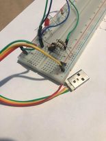
-Now we need to build the following circuit to be able to pass the bootloader to our attiny85.
Chef's Notes:
-The 10uf capacitor is not essential, the other connections are necessary so that you can pass the bootloader to the attiny85.
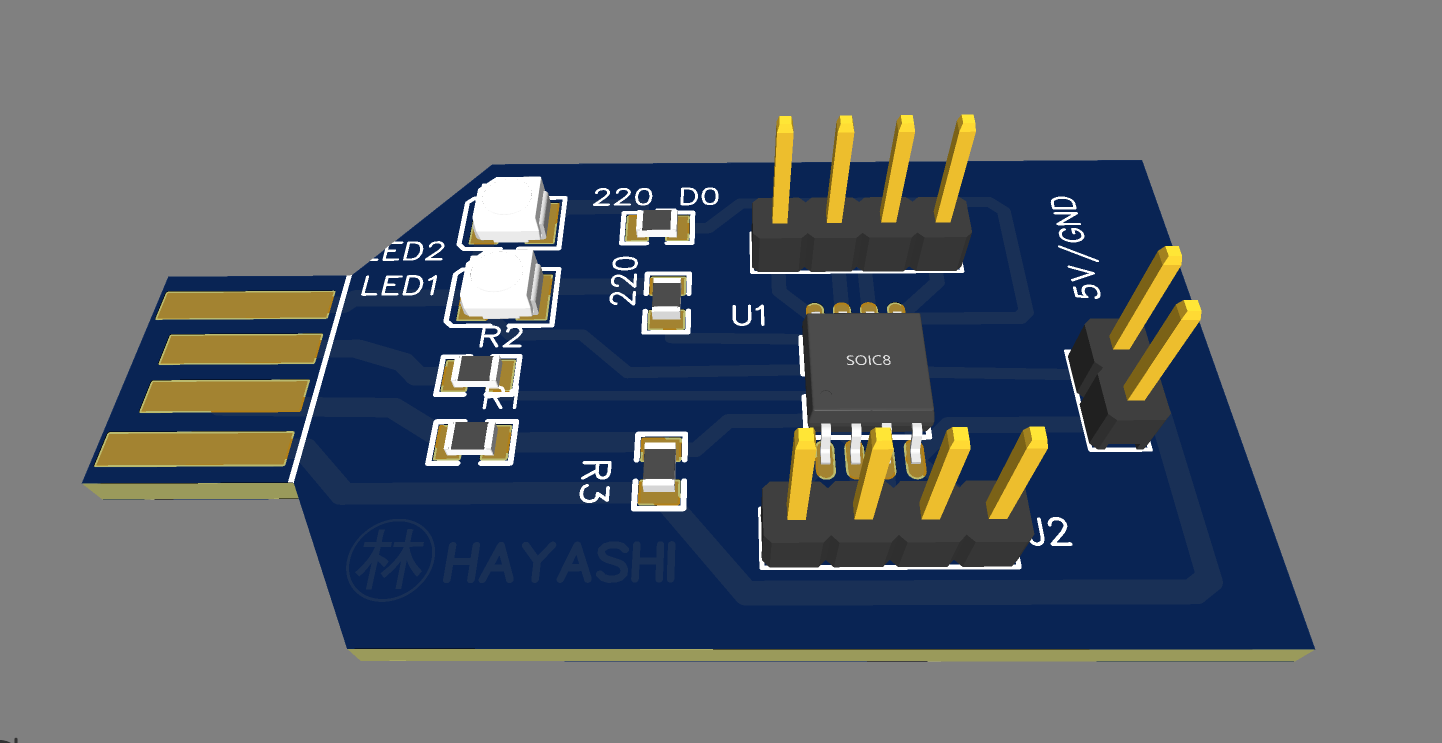
We did the circuit based on the same electronic card that we baptized with the name of Fabtiny, after making all the connections and also the programming in arduino, our electronic card has the following appearance:
-Now it is the turn of the bootloader, we must download it from here.Finally we must edit the file "Burn_AT85_Bootloader" and change the command "-PCOM4" ”By the port where our arduino is connected (we can find it through device manager or arduino tools).
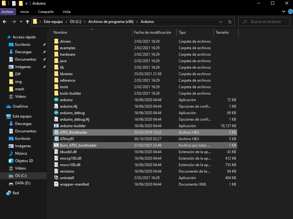
-Now we must copy those 2 files and copy them directly to the root of our arduino folder.
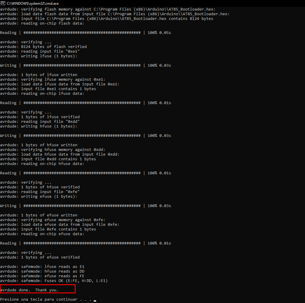
-Now we just have to execute the file "Burn_AT85_bootloader" and a final screen should be generated with the message "avrdude done" like this:
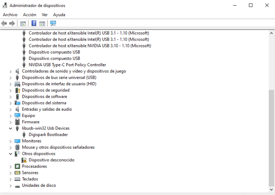
-The moment of truth has arrived (solder your booted attiny85 to your PCB), we connect our board and we will hear the sound of victory (the tucutum that recognized a USB) and you can check it through the device manager:
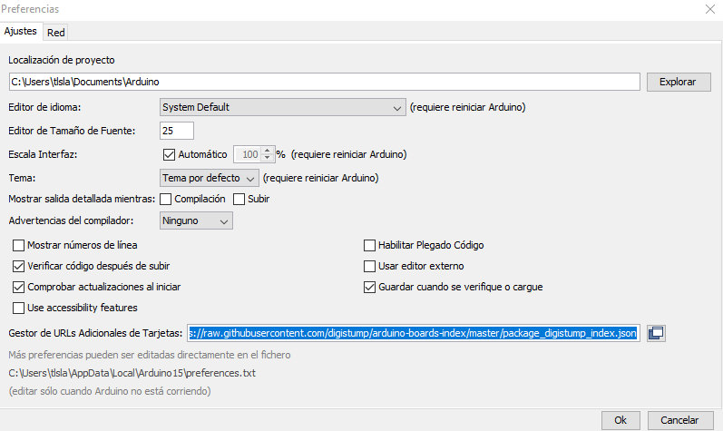
-Your board must recognize as a "Digispark" module, it's time to test our new mini arduino. Now we must install a new board manager in our arduino, for this we go to "file / preferences" and put the following (http://digistump.com/package_digistump_index.json ):
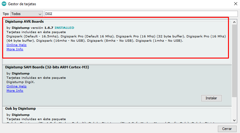
-Then we go to "tools / boards / card manager" and look for "Digistump AVR Boards"
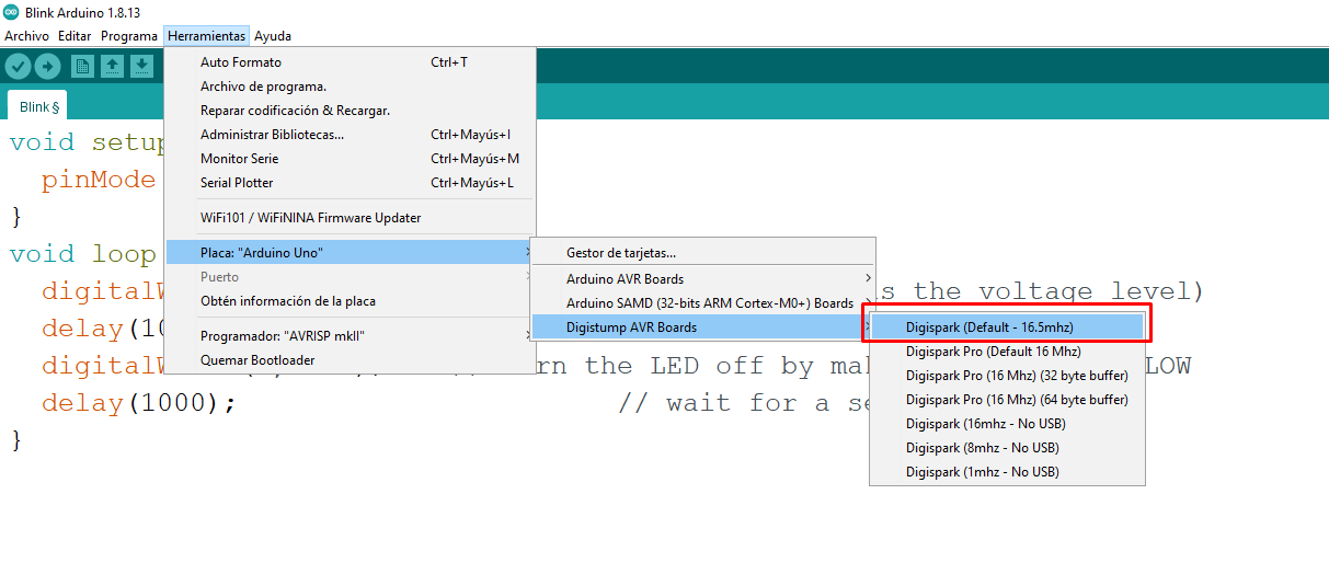
-Now we just have to choose the correct plate:
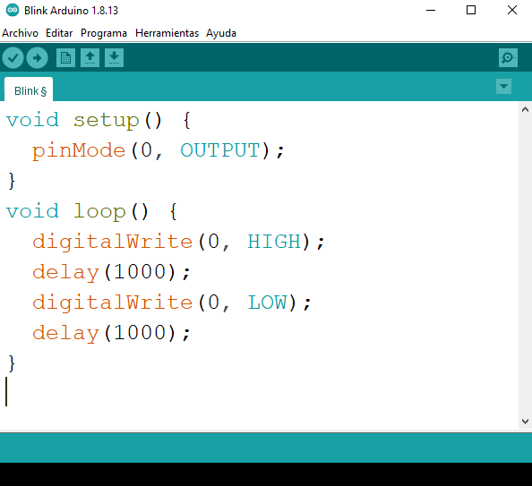
-Finally we uploaded a program and EUREKA, we have achieved it.
Final comments:
-This mini arduino has a very curious way of programming, you must upload it without having it connected and then in the black console below it will notify you so that you can connect it.