Programming
For the programming, a variable called color was created which will represent each color that we will program and in turn will save the state in which the color is found, for this we have considered 5 states, the initial being the off state, this programming was elaborated only with if conditions and boolean algebra so that it can be a double condition, taking into account that it can only advance to a state if it comes from the previous one designated and the clap has been executed.
					float COLOR = 0;

					void _delay(float seconds) {
					  long endTime = millis() + seconds * 1000;
					  while(millis() < endTime) _loop();
					}

					void setup() {
					  pinMode(9,OUTPUT);
					  pinMode(10,OUTPUT);
					  pinMode(11,OUTPUT);
					  pinMode(2,INPUT);
					  analogWrite(9,0);
					  analogWrite(10,0);
					  analogWrite(11,0);
					  COLOR = 0;
					  while(1) {
					      if((digitalRead(2) == 1.000000)  &&  (COLOR == 0.000000)){
					        COLOR = 1;
					        analogWrite(9,255);
					        analogWrite(10,0);
					        analogWrite(11,0);
					        _delay(0.5);

					      }
					      if((digitalRead(2) == 1.000000)  &&  (COLOR == 1.000000)){
					        COLOR = 2;
					        analogWrite(9,0);
					        analogWrite(10,255);
					        analogWrite(11,0);
					        _delay(0.5);

					      }
					      if((digitalRead(2) == 1.000000)  &&  (COLOR == 2.000000)){
					        COLOR = 3;
					        analogWrite(9,0);
					        analogWrite(10,0);
					        analogWrite(11,255);
					        _delay(0.5);

					      }
					      if((digitalRead(2) == 1.000000)  &&  (COLOR == 3.000000)){
					        COLOR = 4;
					        analogWrite(9,0);
					        analogWrite(10,0);
					        analogWrite(11,255);
					        _delay(0.5);

					      }
					      if((digitalRead(2) == 1.000000)  &&  (COLOR == 4.000000)){
					        COLOR = 5;
					        analogWrite(9,255);
					        analogWrite(10,0);
					        analogWrite(11,255);
					        _delay(0.5);

					      }
					      if((digitalRead(2) == 1.000000)  &&  (COLOR == 5.000000)){
					        COLOR = 0;
					        analogWrite(9,0);
					        analogWrite(10,0);
					        analogWrite(11,0);
					        _delay(0.5);

					      }

					      _loop();
					  }

					}

					void _loop() {
					}

					void loop() {
					  _loop();
					}
Once we confirm that the code is running correctly it is time to focus on the shape of the lamp.
3D PRINTING
For the 3D design, I will use a technique called lithophany which consists of showing shapes through reliefs, this is something fabulous since at first glance there does not seem to be anything but when you oppose a light, you can immediately see all the reliefs. Finally a piece was designed in blender that could contain the different photography walls that they were going to have.
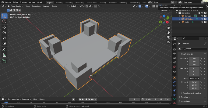
For the design, we will first open our blender program which will help us to make the base of the structure, as this is only a straight structure, it will be much easier to do it, first we create a cube and this cube we enlarge it to be able to support the following structures.

now we are going to create the corners of our support, for this it is not necessary to do much design, what we will do is start with a cube and thanks to the boolean tools of blender we will be able to remove the volumes and generate a cut.

Finally we copy the created piece and position them in each of the corners of our design to finally create the base.
The flashprint program has a built-in tool which helps us to transform images into a relief format that can be laminated to be printed, you just need to place the photo and print it as in the example.Once everything was designed, it was time to assemble everything and put it to the test, the final result was as follows:
Litofania
3D Rocks:
Now is the time to make the images, this technique is called lithophany, which tells us that by means of reliefs specific figures can be noticed as if it were a photograph, this technique can be noticed as long as there is a light that passes through the material with which the piece that has this technique was manufactured.

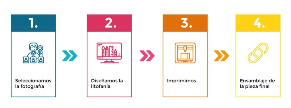
The process to get to this form has multiple ways to do it, the first is directly using a program to do it manually, but that would be very tedious and would take us a long time, for this everything must start with an image which will be processed in a software to then be printed and assembled with the others, as indicated in the image of the process below.
Let's start with the image we must first select any image, this works excellent with photographs too, however I will use a test image so you can see how the process is.

The program that we will use for this is called 3D rocks, however it is not the only program that exists.

Finally, we only upload our image and then we can see that the program has already done all the work, after that, we only have to download the stl and be able to print it. As you can see, 3Drocks is a very simple solution when processing images and transforming them in a lithophane format.

Finally, it is also very important to note that we can modify different parameters and characteristics of this process if we go to the settings section, however, in my experience, the work that 3drock does by default is already more than enough to be able to print correctly. our images.
3D Builder:
The following program is not a program that can be used online, however, it is mostly a program that already comes in Windows operating systems and always goes unnoticed, I mean the program called 3D Builder, this program was born as a program for 3d design, however, has a particularity that also allows us to convert images into 3d design through this technique.

Once the program is open we have to go to the option to open new and the option to load an image will appear.

The result that it gives us may be a bit discouraging, however, like 3drocks, it has different options which allow us to modify it.

After some configurations, the result that we are left with is this, we can come to the conclusion that this program is not very good when it comes to working with many colors or details, however when it comes to simpler images, it does its job correctly.
 Flashprint:
And we come to the end of the programs, we have here the one that in my opinion is the best or my favourite, it is the same flashforge laminating program, exactly, the same program with which we are going to set the printing parameters.

The only thing that this program needs is for us to open the image directly to our printing bed to be able to work or directly size the part, however if it asks us for some initial adjustments like the ones that appear in the following image.

After placing the necessary parameters, it is time to just accept it and be able to contemplate the excellent work that flashprint does when performing this technique.


As a final conclusion, I would recommend working with this software as long as the piece does not need any kind of editing after being transformed into lithophane format, if this were not the case, in that case I would recommend 3drocks.
Flashprint Settings-PLA
Now it is the turn of our flashprint program and its settings, once we have chosen the image that we want to be printed and have made the settings for the lithophane technique, it is time to move on to the settings for its 3d printing, in this case A layer height of 0.12 mm was chosen so that the resolution is good but without greatly affecting the printing time. This parameter is very important because if we place it wrong, we will not be able to see any detail in our print.

Once the parameters are in place, it is time to laminate it and see the printing time, as you can see it takes approximately 6 hours per impression, so we have time for a while until the impressions of all the faces come out.

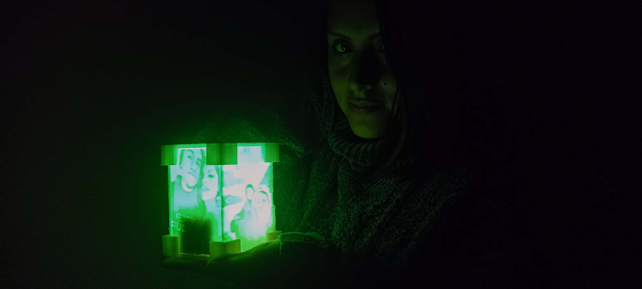
After many hours, we finally have our print finished and this is the result we have, as you can see at first glance the image cannot be seen correctly but that will be fixed after placing the lights.

Finally and after placing all our components, this would be our result.


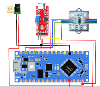 Additionally we will have to make the connections by means of jumpers that would be soldered to each of our components, we also add a switch that will allow us to turn our lamp on and off.