Inicio
Wednesday ,April 21
Hello everybody! I hope you are doing very well, this week I will be direct and apply one of the greatest methodologies of my life, the minmax, which tells us that with fewer resources we can wait. This week we have to connect some devices to each other using any type of module, at first I had the idea of doing it through TCP / IP protocols or some wireless wifi module, but I was surprised that the goblins that hide things in me My wifi modules disappeared (haha it's a lie I don't believe in elves, those modules must be around there), so I found some old radio frequency modules that I had used for a remote control cart, so I disassembled it and I will use it (forgive me cart but this mission will not be done alone), so without more to say !Let's do it¡ .
Components/Functioning/Circuit/Video
First Mission
In this mission I have carried out two tests, the first one is made around different devices than the second test.
Components:
The components that we are going to use are the following: -Xbee: This is a long-distance communication module, it works through the zigbee communication protocol, which guarantees the correct arrival and sending of information. Therefore, we need 2 of these so that one can send information and the other receive it.We can see more information about this xbee on the manufacturer's page (Sparkfun).

-Parkyt: Our favorite board of all this fabacademy can also participate in this mission because the attiny85 can also communicate serially through its digital pins, this makes things much easier because the communication of our xbee module works through serial communication.
-Arduino Nano:We also need our friend the arduino, actually we could do it with two parkyt boards but since we only have one, we are going to make the data reception module controlled with an arduino nano.
-LCD - I2C :In order to show the messages that come through the modules, we need somewhere to show them and that is why we will use our lcd screen with its i2c module to make the connection more efficient.
For the development of this mission it is very important that we know that this system has 2 subsystems, the emitter and the receiver, which have different components and circuits, as we can see in the image.
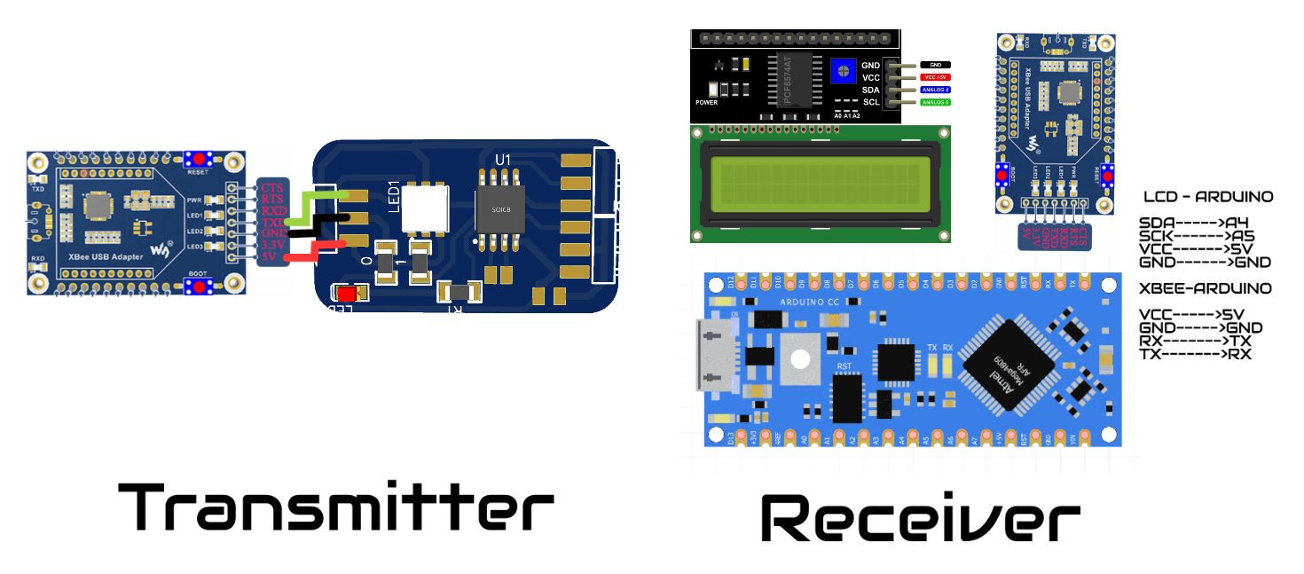
Transmitter:
The transmitter is the simplest part of the system because its connections are direct as we saw in the image of the circuit.
 As for the code that our Parkyt will have, it is also something basic, first we must know that the serial communication pins are not predetermined, that is why by programming we must use two of its pins to be its serial port.
#include <SoftwareSerial.h>
const int rx=3;
const int tx=1;

SoftwareSerial emisor(rx,tx);

void setup()
{
pinMode(rx,INPUT);
pinMode(tx,OUTPUT);
mySerial.begin(9600);
}

void loop()
{

emisor.println("FABACADEMY");
delay(1000);
emisor.println("2022");
delay(1000);
emisor.println("HAYASHI MATEO :D");
delay(1000);
}
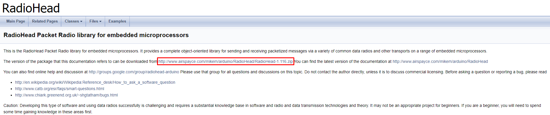
Now it is our xbee's turn, the xbee modules have different modes but this time we are interested in the transmitter or router mode, through this mode we can only send messages to other modules, for this we must first download and install the program on the following page.

By connecting our xbee and opening the program, we can see that the module is recognized, then we must configure it as a router, for this we only need to modify the 2 parameters that are in the image, the first is the PAN ID, this is the number with the which all the modules that have the same will be able to communicate, finally put the coordinator option disabled and that's it we already have our modules configured.
Receiver:
This part of our system may be a little more complicated than the previous one due to the connections that have to be made, but nevertheless they are already in the previous images, to make these connections we use jumpers to facilitate the connections.
 In turn, the programming of this is not so complicated because they are all known modules, as you can see the programming is at the bottom.
	#include <Wire.h>
	#include <LiquidCrystal_I2C.h>
	LiquidCrystal_I2C lcd(0x27,16,2);
	void setup(){
	  lcd.init();
	  lcd.backlight();
	  Serial.begin(9600);
	}

	void loop(){
	  if (Serial.available()) {
	    delay(100);
	    lcd.clear();
	    while (Serial.available() > 0) {
	      lcd.write(Serial.read());
	    }
	 }
	}
In the case of the xbee, now we have to be able to configure it as a coordinator, because it will be the one that will receive all the messages from the router, for this we only have to connect our module and then put the same PAN ID number and place the option of enabled. coordinator.

Finally we have the end result of our mission.
Group assignment
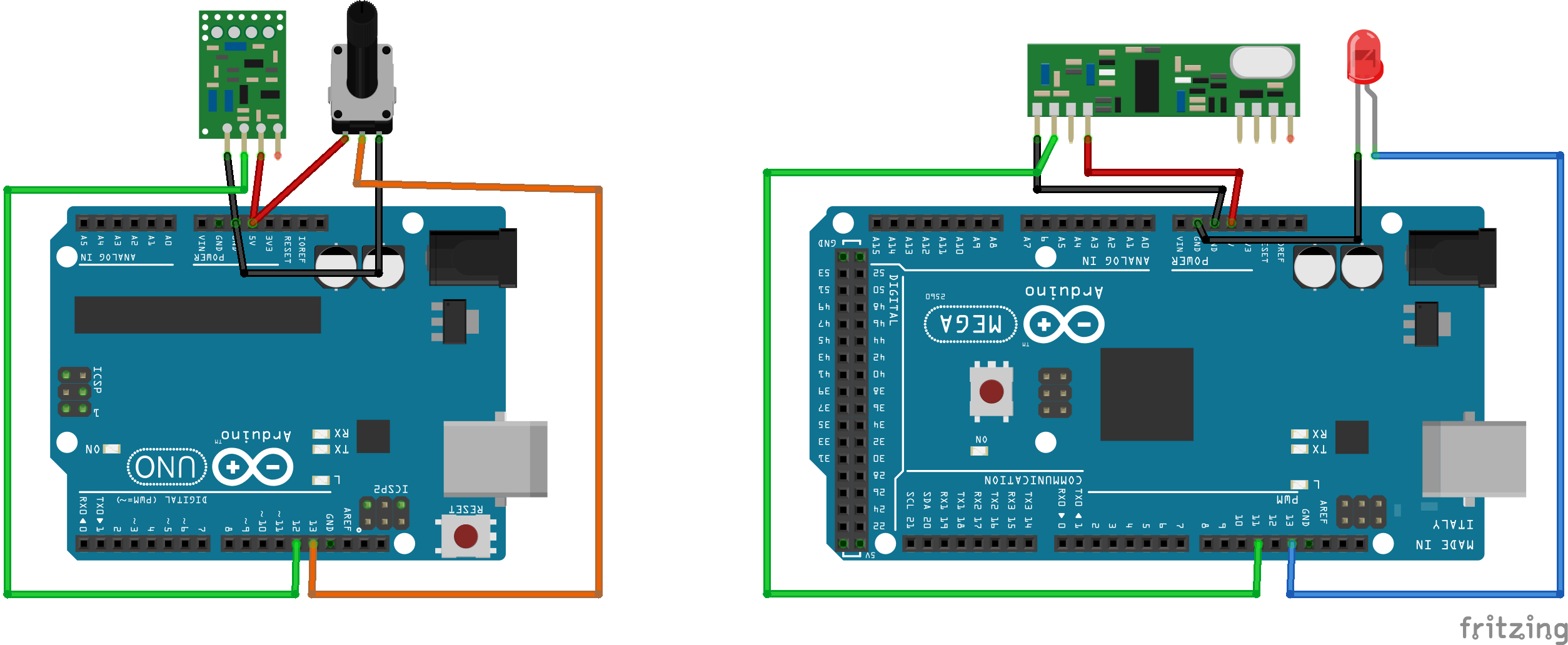
The challenge for this week is a little simpler than the previous ones, we must connect 2 devices and send data to each other, for this as I mentioned earlier I am going to use radio frequency modules from a cart I had (RIP cart), but the question is "What will you do with those modules?" well what I will do is that in the emitter I will place a potentiometer and in the receiver I will place a led, the potentiometer will send analog data and this will be received by the receiver and then sent to the led by means of a digital pin, simple right? Haha don't worry, I'll do it step by step, in the end the project will look like this:

Do you want to know how I did it? Join me to see it.
The components
-Emitter Arduino:
The emitter Arduino can be any Arduino that we have available or any microcontroller that has pins 11 and 12 available because the library that we will use works with those pins (if you work with another library you can use any Arduino), in my case arduino receiver is the arduino uno.
 -Arduino receiver:
The arduino receiver has the same requirements as the arduino emitter, it is only required to have pins 11 and 12 because the library works with these pins, in my case the arduino receiver is the arduino mega.
-Arduino receiver:
The arduino receiver has the same requirements as the arduino emitter, it is only required to have pins 11 and 12 because the library works with these pins, in my case the arduino receiver is the arduino mega.
 -Potentiometer:
The potentiometer will be in charge of sending the signal between 0 to 255 so that the receiver, upon receiving it, can control the light intensity of the led.
-Potentiometer:
The potentiometer will be in charge of sending the signal between 0 to 255 so that the receiver, upon receiving it, can control the light intensity of the led.
 -RF 433 Mhz:
These will be the modules which will be in charge of sending the data between them, the curious thing about these modules is that they can withstand voltages of up to 12v and as the voltage increases their range of reach also increases, being able to reach approximately 4 meters. Keep in mind that these modules come without an antenna so you must solder a cable that serves as an antenna.
-RF 433 Mhz:
These will be the modules which will be in charge of sending the data between them, the curious thing about these modules is that they can withstand voltages of up to 12v and as the voltage increases their range of reach also increases, being able to reach approximately 4 meters. Keep in mind that these modules come without an antenna so you must solder a cable that serves as an antenna.
 -Led:
Finally we need a led to be able to see if the data sent by the receiver is being received and also sent to the digital pin of the led.
-Led:
Finally we need a led to be able to see if the data sent by the receiver is being received and also sent to the digital pin of the led.
 -Power supply:
Im using a portable charger in the case of the transmitter and in the case of the receiver I use the PC because I am also seeing the data received by the serial monitor.
-Power supply:
Im using a portable charger in the case of the transmitter and in the case of the receiver I use the PC because I am also seeing the data received by the serial monitor.