Inicio
Wednesday ,April 21
Hello everyone, welcome back to this your favorite profile of "improvising with electronics", just kidding, well this week was a little more interesting than the previous ones and by interesting I mean that it was very challenging, starting with the move From the FabLab to a new place and with the challenge of fulfilling the assigment with the materials that I had at home, join me to see this medley of trial, error and much more.
Components/Functioning/Bootloader Attiny85/Group assignment
The challenge
For this week's mission, it was asked to connect our board to an output device or also known as actuators, following the line of the previous mission in which I made the breathalyzer (see it here) and taking into account that I have fewer and fewer weeks left. (I swear to you how time flies, sometimes it scares), it is time to connect an OLED screen to my motherboard, however on the way I resolved that I do not need a super microcontroller to do that activity, that is why I used our dear Attiny85 (I swear to you, I love this microcontroller) so that it can connect with a 128x64 dimension Oled screen, so that it is something similar to this:

Do you want to know how I did it? Join me to see it.
The components & Group assignment
Only a couple of components will be needed for this mission
For this mission the components are almost the same from the previous mission or from week 4 in electronic production, however I will mention them right now:
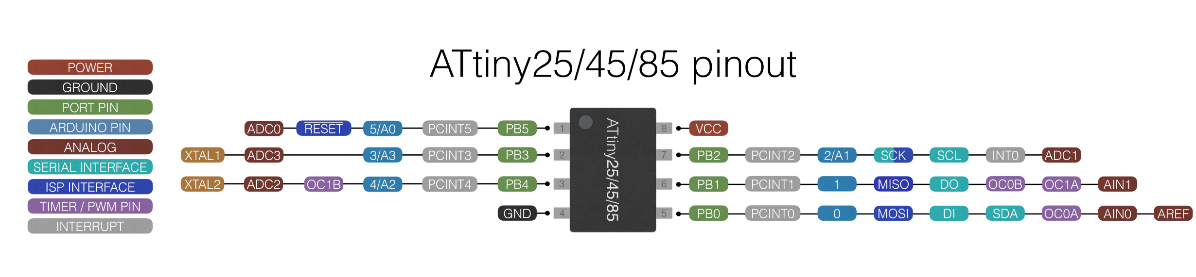
-Attiny85:
 -MQ3 sensor :
 -OLED SSD1306:
 Initially these are the most important components, however if you want to do some programming tests you will need some additional components in case you do not have a board for the attiny85, these are the following:
-Mini Breadboard
-Usb male A
-Res 220 ohms x2
-Res 1k ohms x1
-Jumpers
Initially these are the most important components, however if you want to do some programming tests you will need some additional components in case you do not have a board for the attiny85, these are the following:
-Mini Breadboard
-Usb male A
-Res 220 ohms x2
-Res 1k ohms x1
-Jumpers
For this mission we will use an electronic board that was already manufactured in previous missions, which in this case we named fabtiny because it is built around the attiny85 microcontroller, which is one of the most versatile microcontrollers of all, it is also compatible with arduino as well. that allows us easy programming with our electronic components.

These will be for the assembly of the attiny programmer (it is only necessary if you do not have an attiny programmer), there are other ways to program the attiny85 such as connecting it with another arduino through ISP or through the ICSP pins, which you can review here.

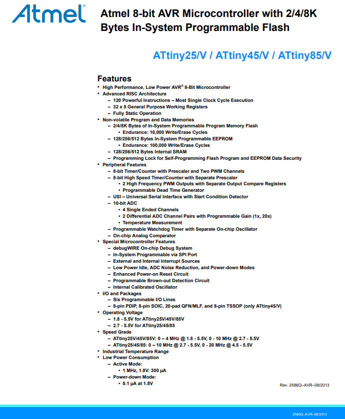
This microcontroller is very particular due to its low current consumption and also because it can be used with different actuators and sensors, as if that were not too much, it also has the possibility that it can be articulated with the Arduino bootloader and be able to program it directly. with arduino, besides that it can also be used for other projects and due to its size it lends itself a lot to other designs.
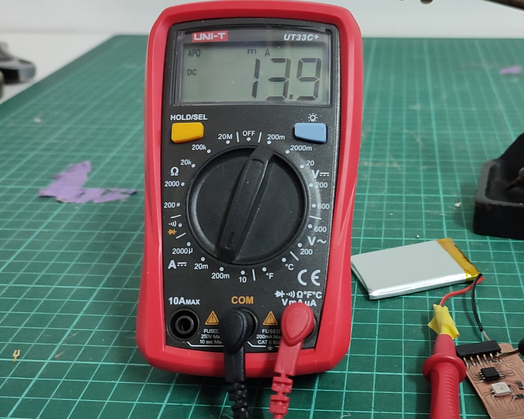
If we want to explore a little more about this microcontroller and its benefits, we can easily visit its datasheet in which all its functions appear or we can also appreciate it in the following image in which it certifies that this microcontroller by itself can consume about 300 ua which is surprising for a microcontroller and which would give way to only the use of current through the sensors and actuators.