Output Devices
Hello, FabAcademy Friends! Welcome to another very feared week in FabAcademy. After the terrible failures in Input Devices week, it was time to redeem myself. It was time to learn from every failure, and finally jump towards the new generation of microcontrollers.
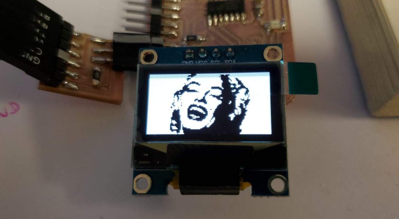
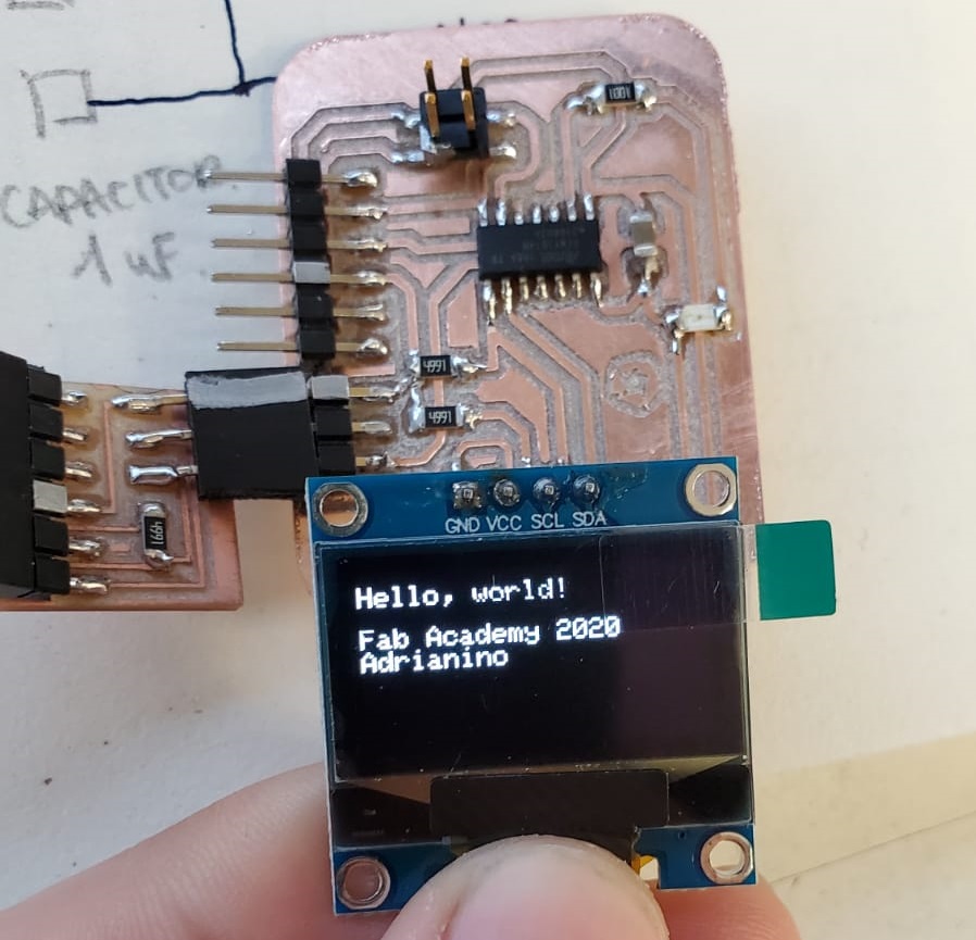
I’m going to program an OLED screen (0,98 inches, 128x64 pixels) with an AtTiny 1614. It did not do exactly what I wanted it to do, but I was happy with the result.
I now want to prepare everything for it to be ready for the networking and communications week, so it can display the information from the RFID sensor. But for now, the basics are done.
If you want to see the nice things you can do with the OLED screen, follow me on this week’s journey!
Chapter One: new week, new board!
For this week’s assignment my goal was to show some text on the display, and also to be able to scroll the text. But in order to control it, I needed a board. Adrián advised me to use Neil’s board for the LCD that is controlled via the i2c protocol . This screens does not need any special external power supply and can be powered with the same 5V VCC that supplies the microcontroller.
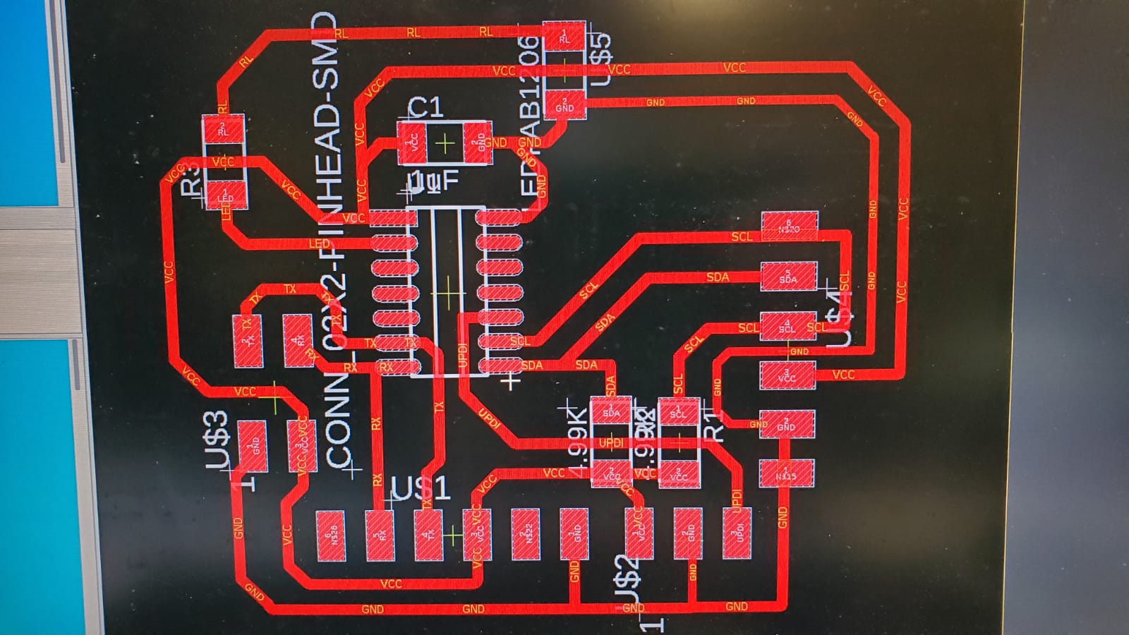
For the debugging process I always include in my boards an LED, but that’s not mandatory. You will need an LED, its resistor, then two 4.99K resistors and a 1uF capacitor, alongside the FTDI connector, the screen connector, the UPDI connector for the programmer (I used Adrián’s original design), and I also included a serial bus connector in preparation for the following weeks, following my instructors tips.
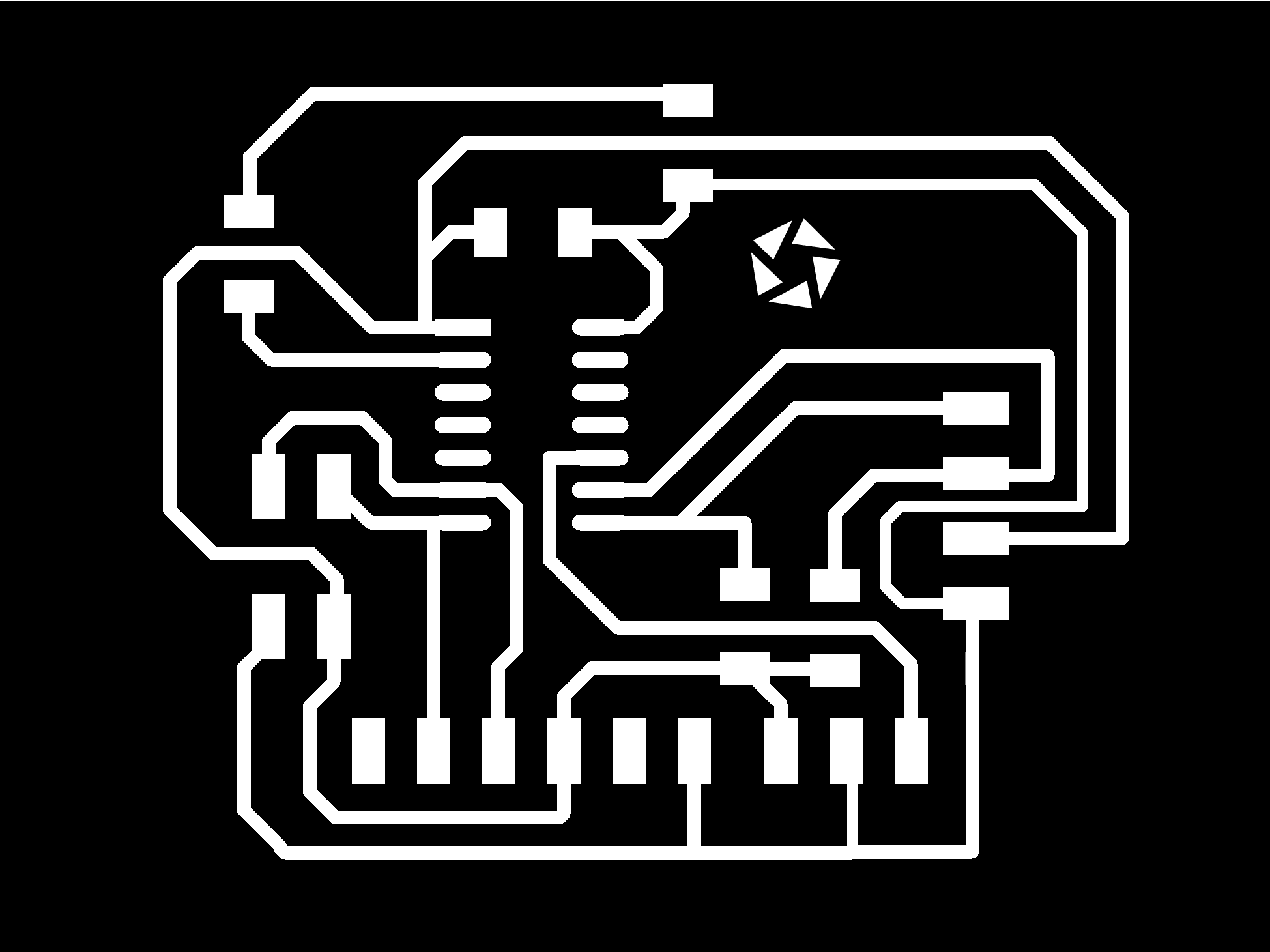
I designed the board on Eagle, and this is how it came out.
You can get the Eagle board file HERE.
You can get the Eagle schematic file HERE.
Chapter Two: (not) everything is well documented
I first wanted to use a Nokia 5110 LCD display (84x48), but Adri and Pablo told me that it was not easy to program. On our Thursday local meeting they told me to use one of the screens that Neil showed in the lesson the day before, so I ordered ON AMAZON. I then joked with my instructor Adrián about the screen: “Im sure it’s on your page already!” Well… it was not (yet). Adrián was working on his documentation alongside myself. He decided to travel this beautyful journey of OLED screens with me, so he was sending me his progress and his documentation, with his tips, successes and failures. He obviously did it first.
However, we found that Last Minute Engineering and Random Nerd Tutorials have amazing codes to work with the screens.
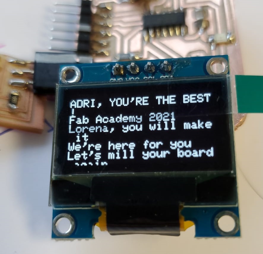
We could not do a proper scroll down however, and that’s something I’m still trying to do.
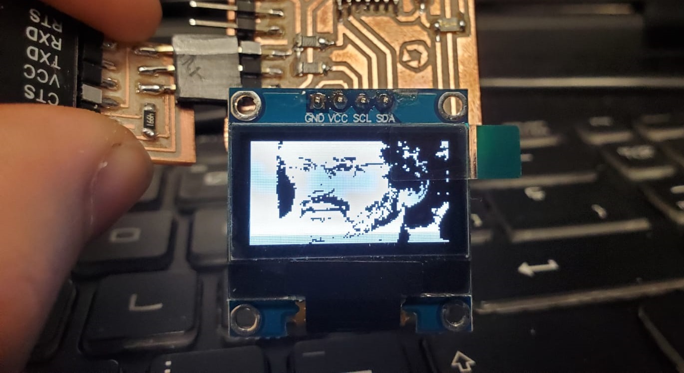
I could display an image, though, as explained HERE.Chapter Three: What to do next?
So now we have seen that it’s relatively easy to display an image or some text.
I’ve included the serial bus on the screen to be able to show information from my RFID device. Will I be able to do it? We will see it in the next assignment.
You can get the code to display Neil's face in your screen HERE.
Group assignment: be careful out there
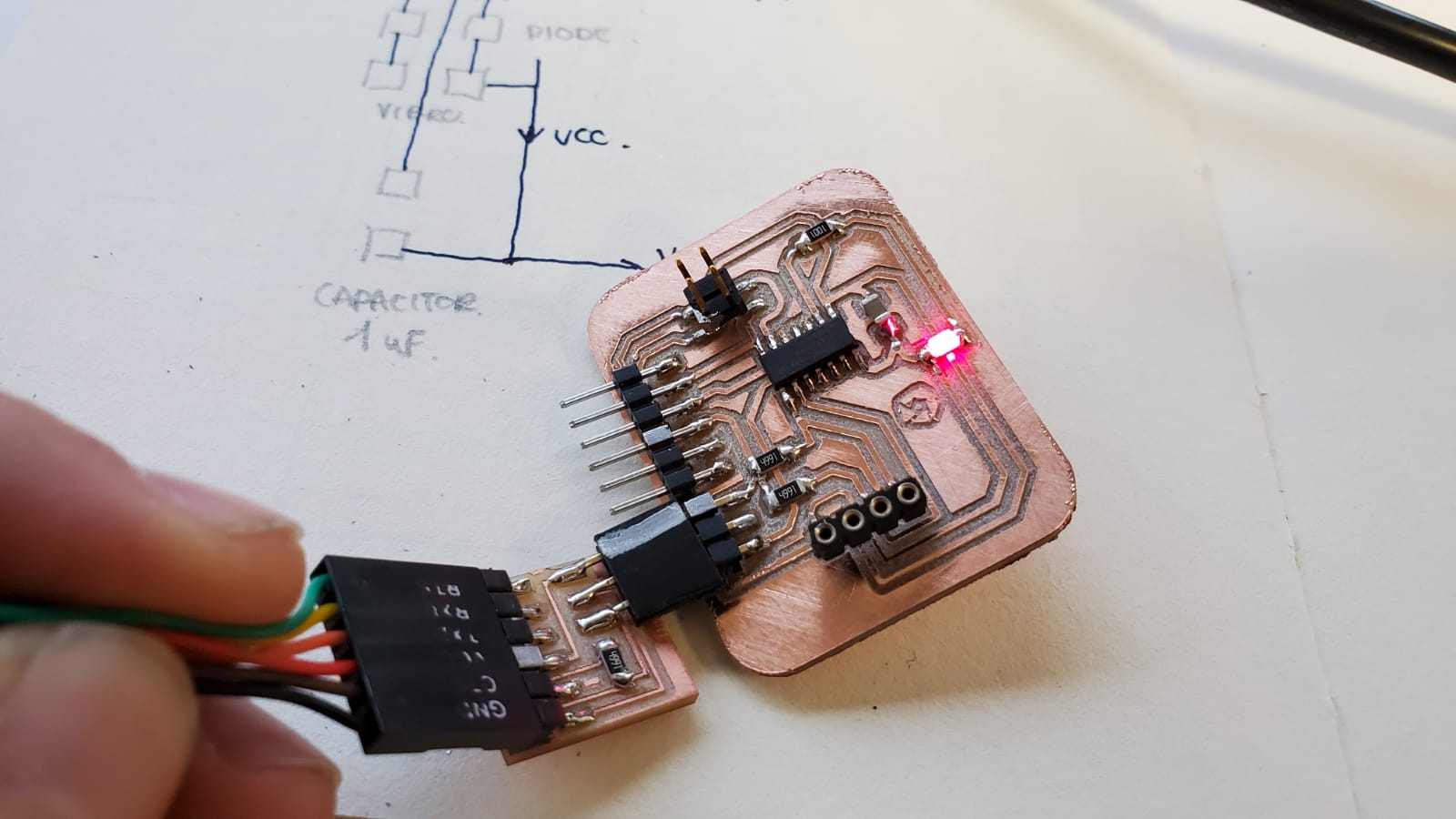
For this week's group assignment I've used the multimeter to measure the power consuption of the board. I placed the multimeter between VCC and GND on my screen and the result was 5V.
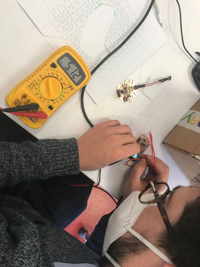
However, because VCC and GND are so close together, I accidentally short-circuited the board for a second. Nothing actually happened, as the screen just turned off and then inmediately turned on again. This served to me as a warning: be careful with the multimeter. I could have destroyed my board completely.
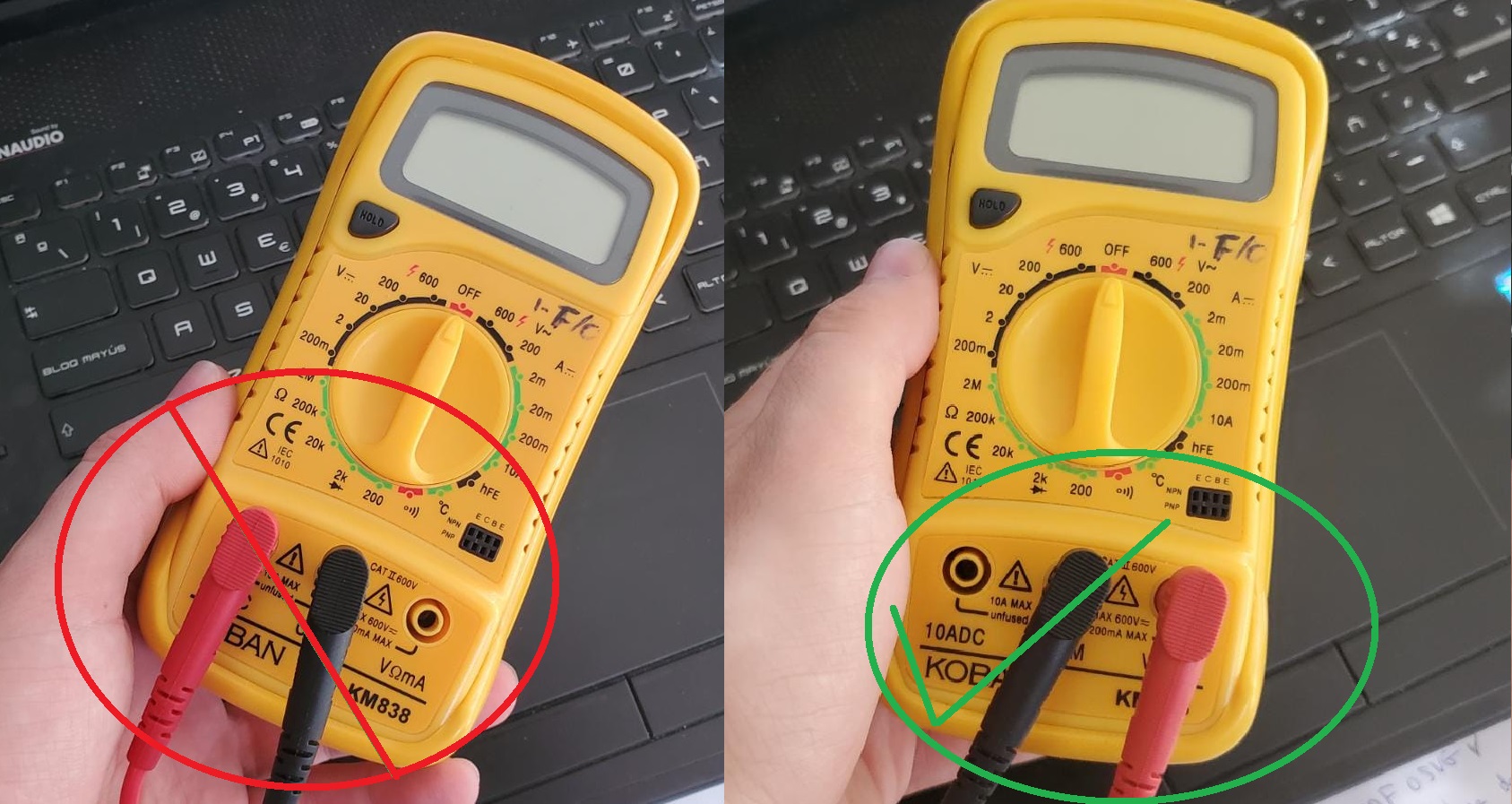
I later found out that I was measuring it wrong. So I tried to measure it as Sergio Herranz was doing.
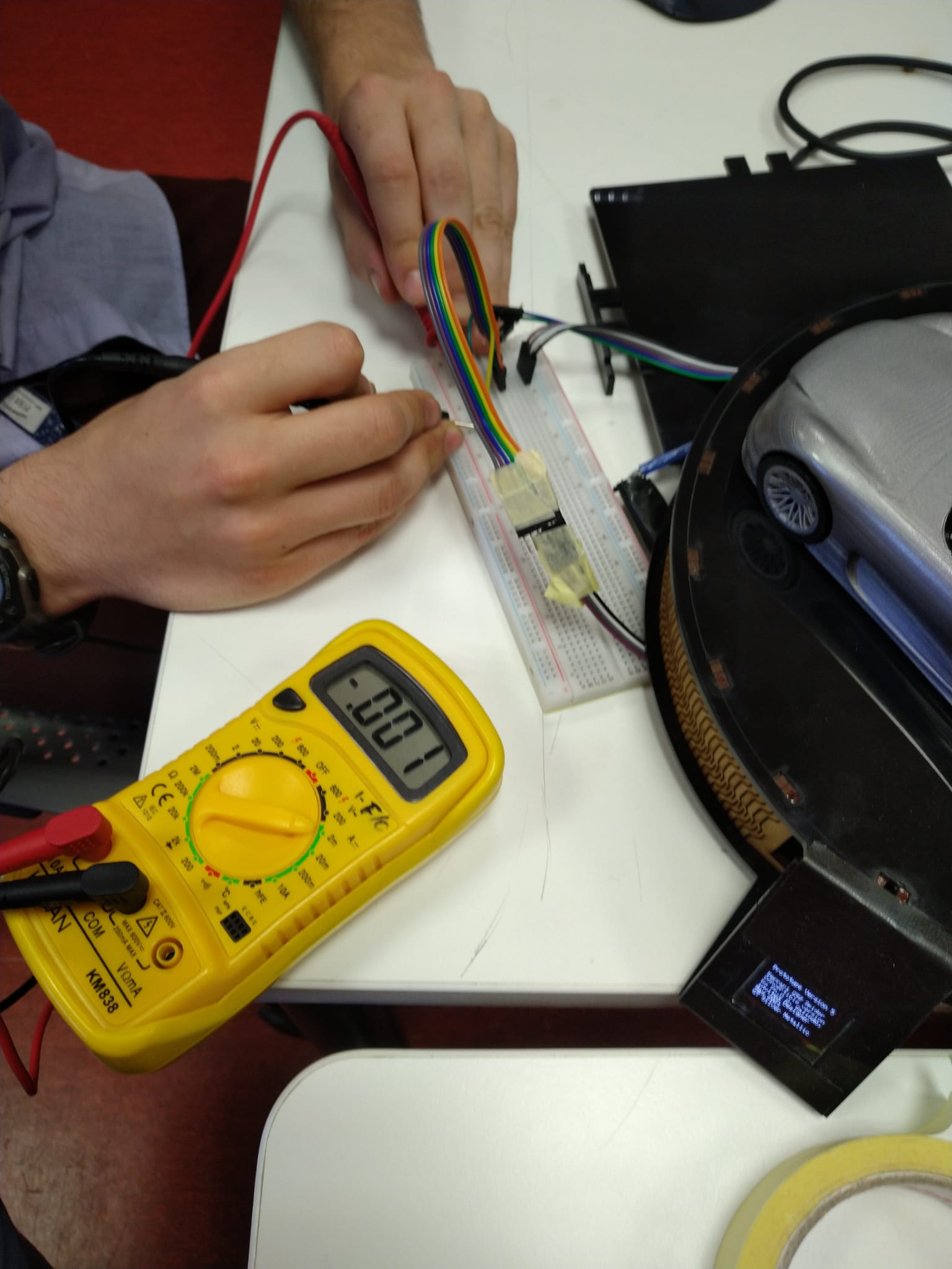
But I was doing it wrong again! The cables of my multimeter were switched around. So I repeated the experiment and I got a power consumption, with a simple text, of 5mA. This made much more sense compared to this amazing article from bitbanksoftware.
I measured the final project screen by placing the multimeter as part of the VCC cable (dividing the VCC cable and placing the multimeter as a jumper in that gap). The current I got was as low as 5 mA. That's very low, but if you read some articules about the current consumption of the OLED displays, like the one from bitbanksoftware, also mentioned earlier, you will see that these screens are actually very frugal on current consumption.
In order to calculate the power:
The current consumption of the screen is 5mA. To know the power, we use the following formula P = V x I.
On this particular measurement, I powered the board with a 5V USB, and we take the consumption of 5 mA.
                            We pass milliamps to amps.
                            P = 5 x 0,005 = 0,025 W.
So that's all for this week, folks! See you in next week's assignment!