Electronics Production
Hello everyone! Welcome to this week's assignment, the very feared Electronics Production week. This is when the hardest part of FabAcademy starts for me, as I have almost zero previous experience with electronics. I've literally haven't touched a resistor since high school. I didn't know what was a programmer, or what was it for. ATTINY sounded to me as a funny word, or like a brand that makes toys for little kids. And now you're telling me that I'm going to try to make a programmer? No. I'm going to try to make two.
(disclaimer: I could not have this assignment done on time without the help of Sergio Herranz, who helped me program the FabISP, and also I have to praise the soldering tips from Nuria and Lorena. Suddenly, Neil's sentence by making you make community is shown as the reason why you fall in love with FabAcademy. My classmates are becoming my friends and I'm having so much fun learning!. Sergio and Lorena are also responsible for some of the great pics that illustrate this assignment)
I'm going to compare the good old way to make PCB boards (milling the copper boards with a Roland MDX-40A mill) to the newcomer in the electronics game, the Voltera V-One
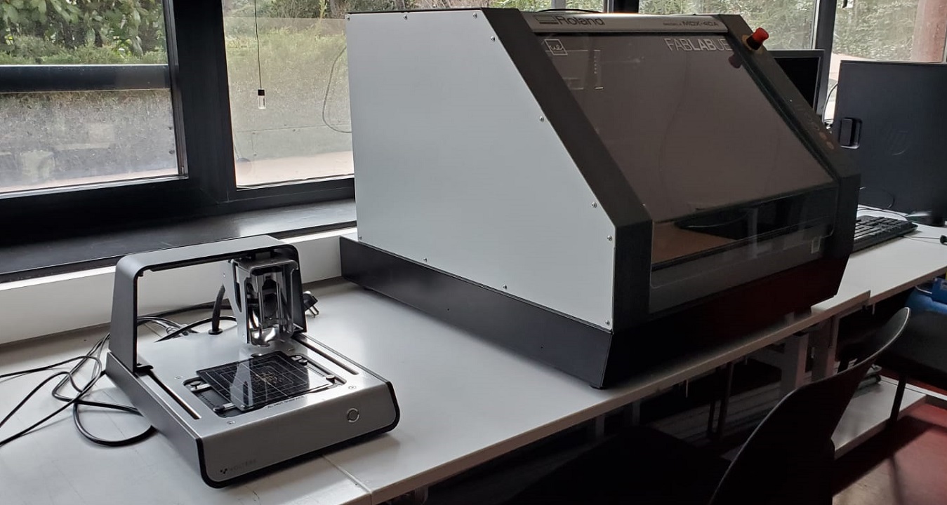
The Roland MDX-40A is an amazing machine. It can mill PCBs with ease, and it's very easy to set up. It uses little mills to precisely machine and cut the PCB tracks in a very short time. It can be used with free software, and even if it's expensive to buy, the boards and the mills are cheap, so everyone can learn how to mill small things, not only electronics related.
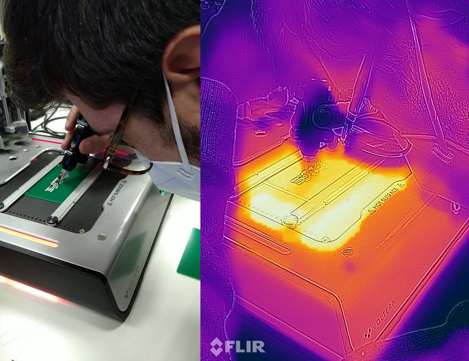
The Voltera V-One is a multi functional circuit printer, that uses a silver based ink to print PCB boards on multiple materials. It's used to create functional boards on FR4 substrates, but it can print on almost anything that has less than 3mm of thickness. The problem is, at 6.000€ for a machine that can "only" print and drill PCBs, It's very expensive to buy, and the ink (that has to be kept in the fridge and also expires after 6 months), the solder wire (that is specific for the Voltera-printed boards) and the dispensing tips for the ink, (that are also a consumable item), should be bought to the Voltera manufacturer, making it also very expensive to run. But can the benefits of its ease of use and self-explanatory and intuitive software overcome the fact that it's so expensive? Let's find out
By the way, we're going to create the FabISP, a in-system programmer for AVR microcontrollers, designed for production within a FabLab. That is, it allows you to program the microcontrollers on other boards you make, using nothing but a USB cable and 6-pin IDC to 6-pin IDC cable.
Chapter One: Regular FabISP with Roland MDX-40A
Step One: Milling the board
I used the Roland MDX-40A with Fab Modules, a very powerful tool that can create the traces for free from a PNG image, freely available online. Mods is the new version of FabModules, even more powerful, but it's not yet available for the MDX-40A. On this softwares you can choose there what machine you're using (FabModules is available for multiple types of CNC mills), what tool you're using, and what for (milling the traces or cutting the outline). However, once you've created the path that the mill is going to follow, you need to communicate with the machine. If you click on "send" on Windows, it does nothing. So you need to save the process, and then send it to the machine with its own software.. When you click Save, it will automatically download a .rml file, that you will have to import on the Roland's software
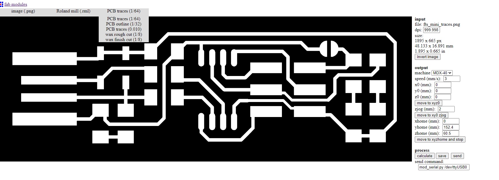
That software is called V Panel (you can download it from here) and from there you can control the machine, move it in XYZ, set the zeros, change the speed of the spindle, and select the .rml file. Remember though that the program only works with the machine attached to your computer via USB cable.
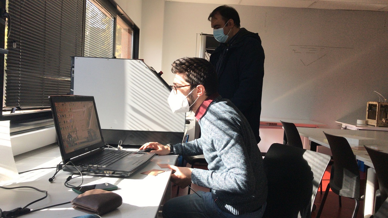
You will be milling in no time. I have the pleasure to work with amazing professionals here in Universidad Europea, and I was very lucky to have Engineer and Professor Sergio Bemposta helping me out. He has a lot of experience milling PCBs on this machine, and he also has a CNC mill at home, so with his help, the board was created with very little damage (only one mill tip was broken in the process). FabAcademy graduated Elena Cardiel also has a nice tutorial on how to use this machine. Make sure to follow this steps:
1: Fix the FR1 copper clad blank to the machine's bed. I prefer using masking tape and fix the board from its perimeter rather than double sided tape, as it's cleaner and I am sure that the board lays completely flat.
2: Mount the correct mill to te machine
3: Set your zeros. Do an XY zero in the place you want to start, and use the sensor to detect the z zero on the surface of your copper blank.
4: Go through the software. Create the traces and send them to the machine. I'm going to show you how to run the whole process in this video:
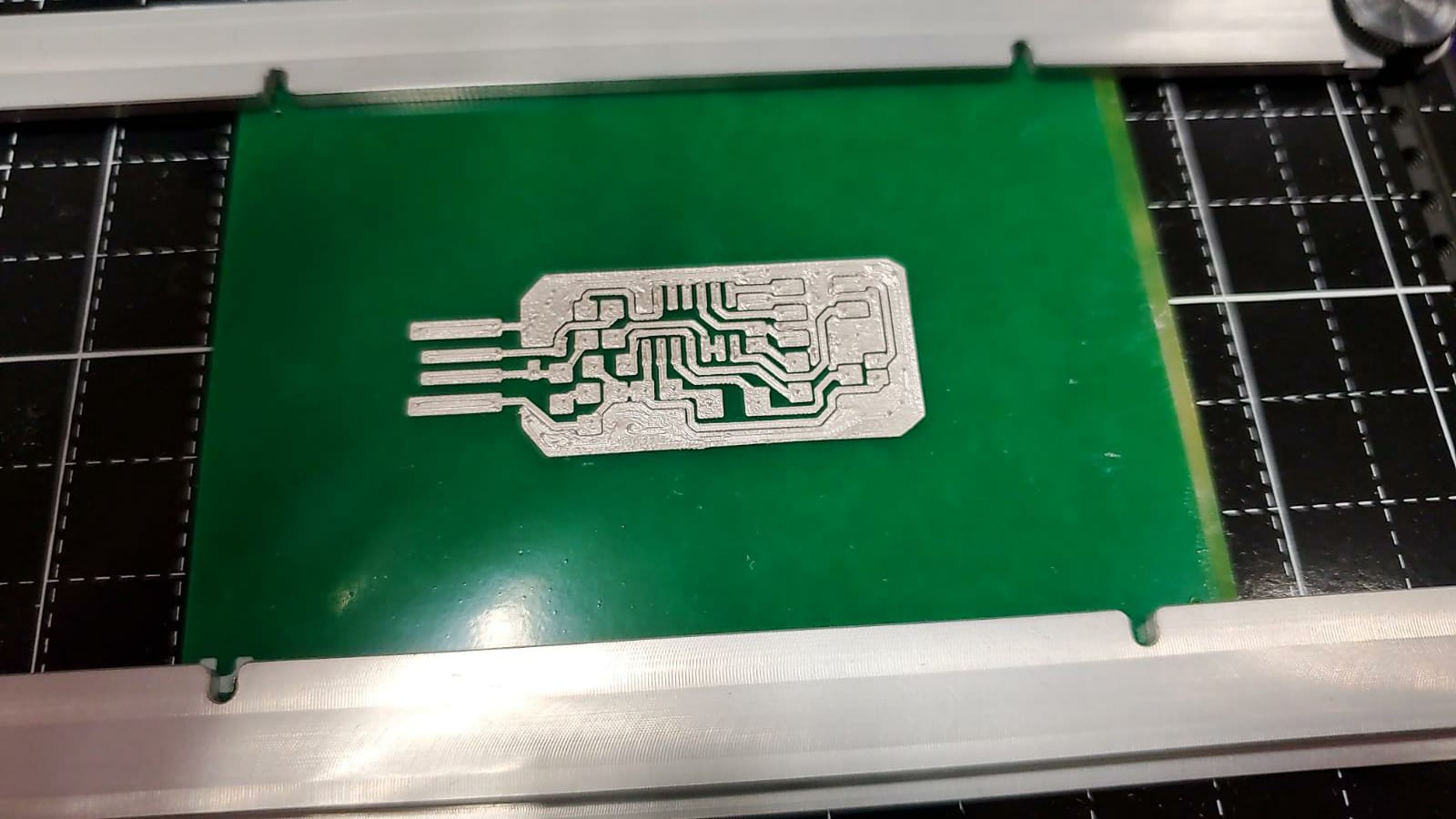
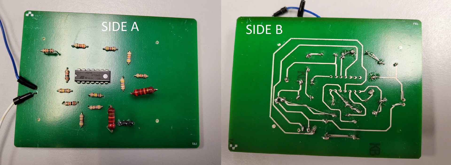
You will have your board milled in minutes.
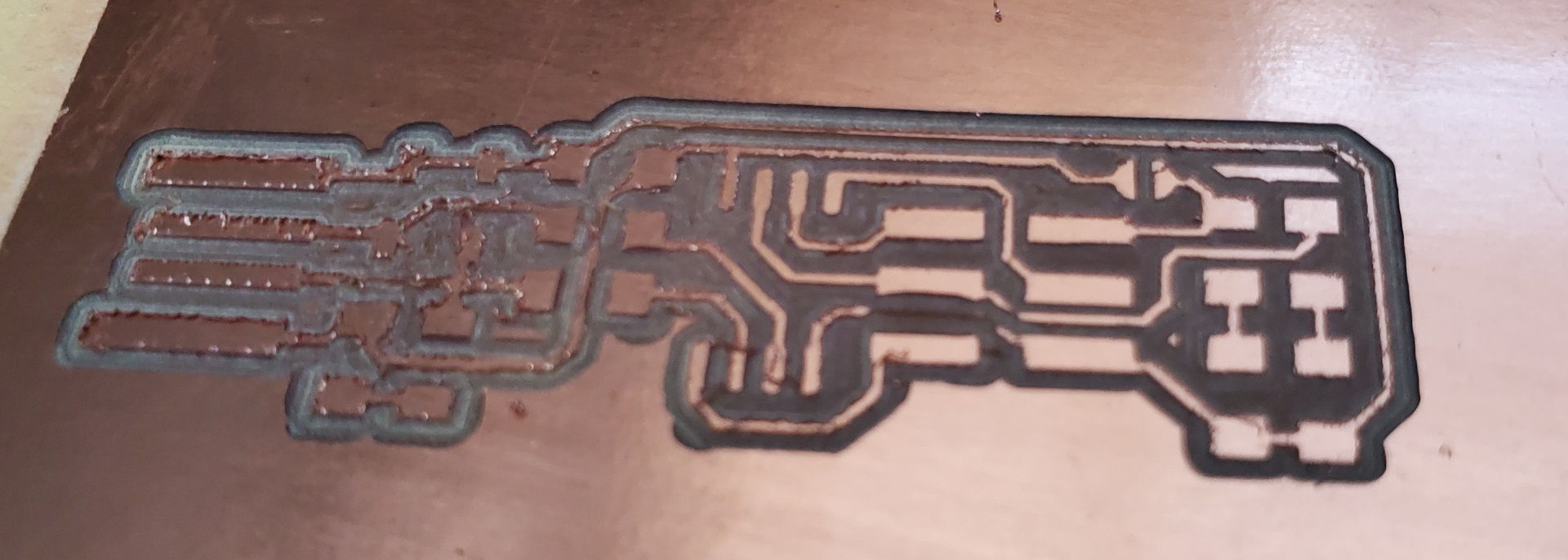
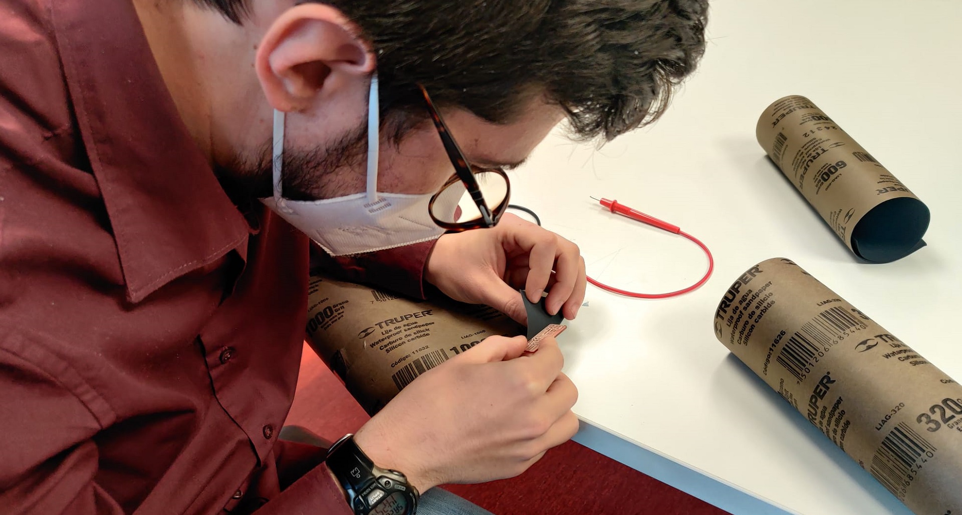
See that the copper is a bit rough? That is because it was milled with a tool with the tip broken. Before soldering, sand the board with very light sand paper. This will help the adhesion of the solder to the board, and will get rid of the roughness of the board.
Step Two: Solder the components
Once the board is milled and cut, you need to solder the components to create the FabISP. The best advice I can give you here is: get a good soldering station, and a nice set of tweezers. Lorena let me used hers and I can guarantee you that it will make the job way easier. You can control the temperature of the soldering tip, and also you can clamp the board and move the components better. Also, follow Duaa's lesson on soldering and practice a lot before starting the actual soldering process, as otherwise you will destroy many boards.
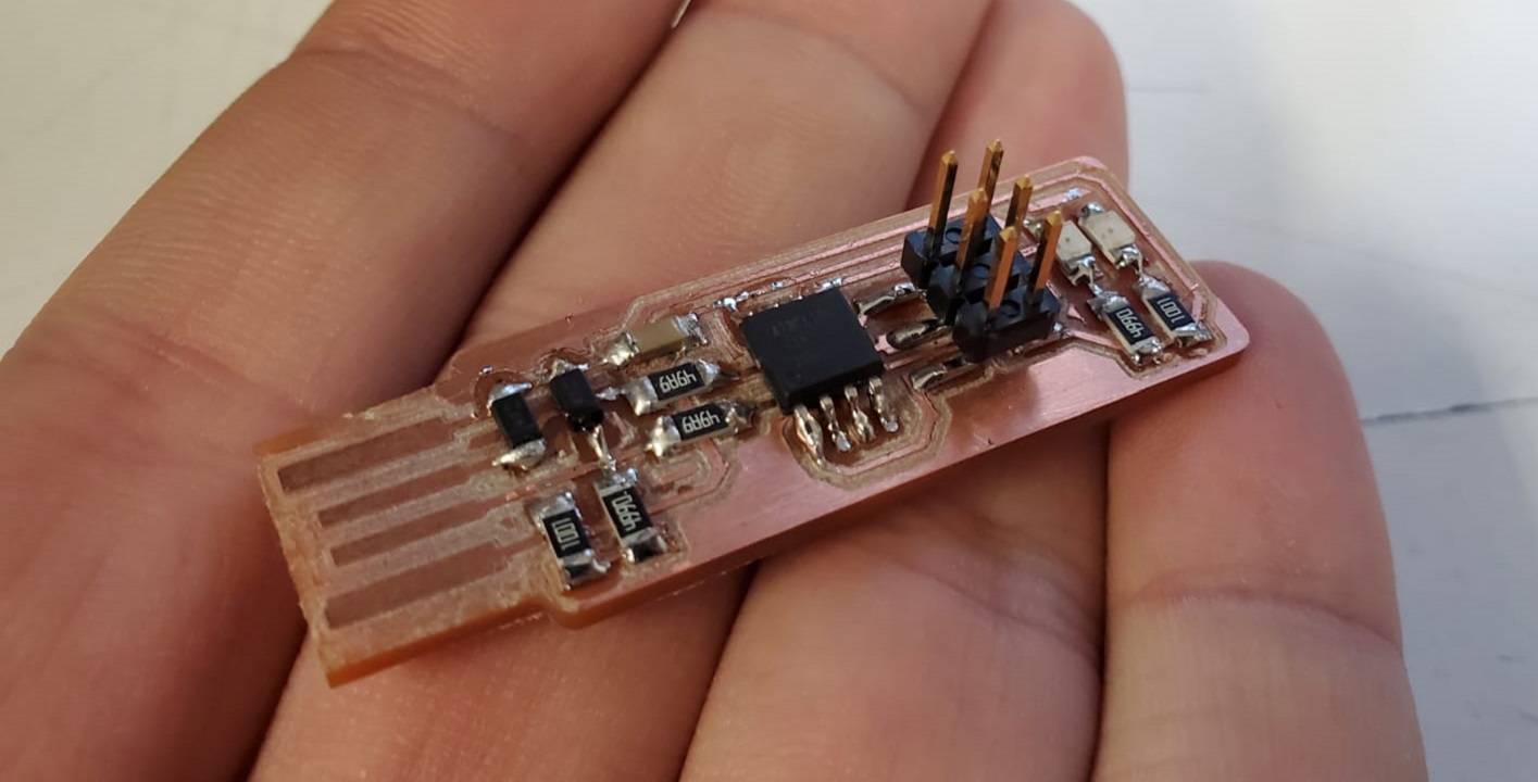
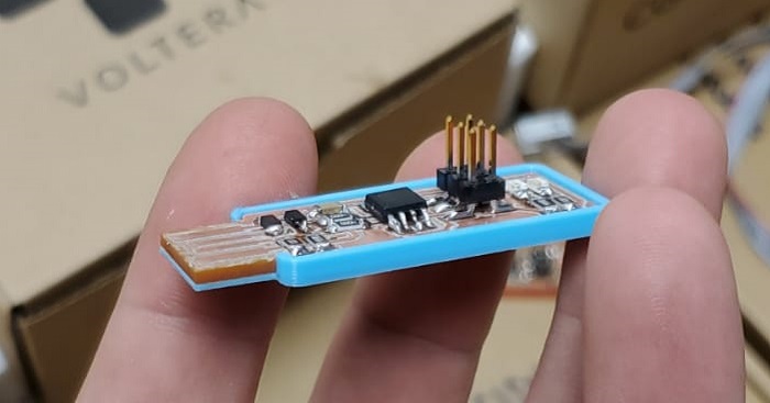
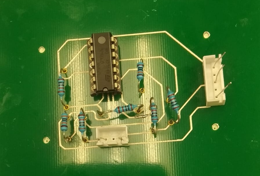
It's recommended to solder from small components to big ones, and from the center to the exterior of the board, like a spiral. The FabISP tutorial that I've followed has a list of all the components that you are going to need. Once you've done, the finished FabISP should look like this (or better):
Step 3: Programming the controller
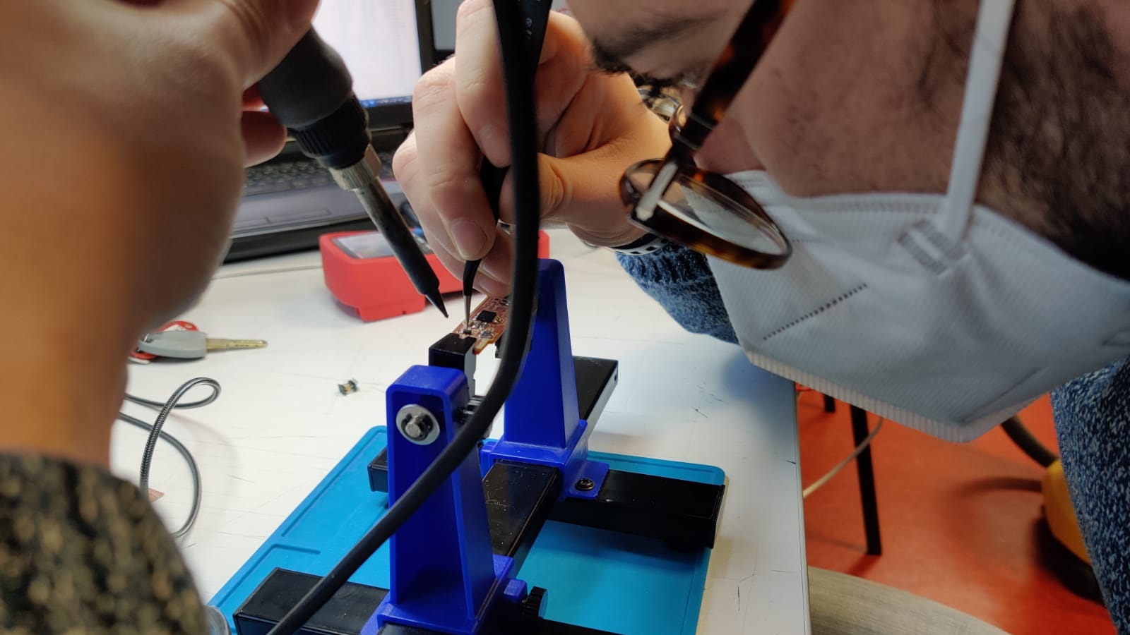
Now it's time for the most complicated part for many, but it was the easiest for me. This instructions are the step-by-step process to program the FabISP on a Windows machine. Also, I have to thank FabAcademy classmate Sergio Herranz, also student from León, who helped me program the FabISP, coming from León to Madrid to spend the Saturday with Lorena and with me in my FabLab. We followed the steps together, and he helped me whith a broken link and some more stuff, so I highly recommend to follow his tutorial. Also, you need to have a working FabISP to program the newer FabISPs, so here I was lucky to have one of Nuria's originals, with its pink LED, handed to me by FabAcademy graduated and now FabLab ESNE coordinator, Alejandro Ulecia.
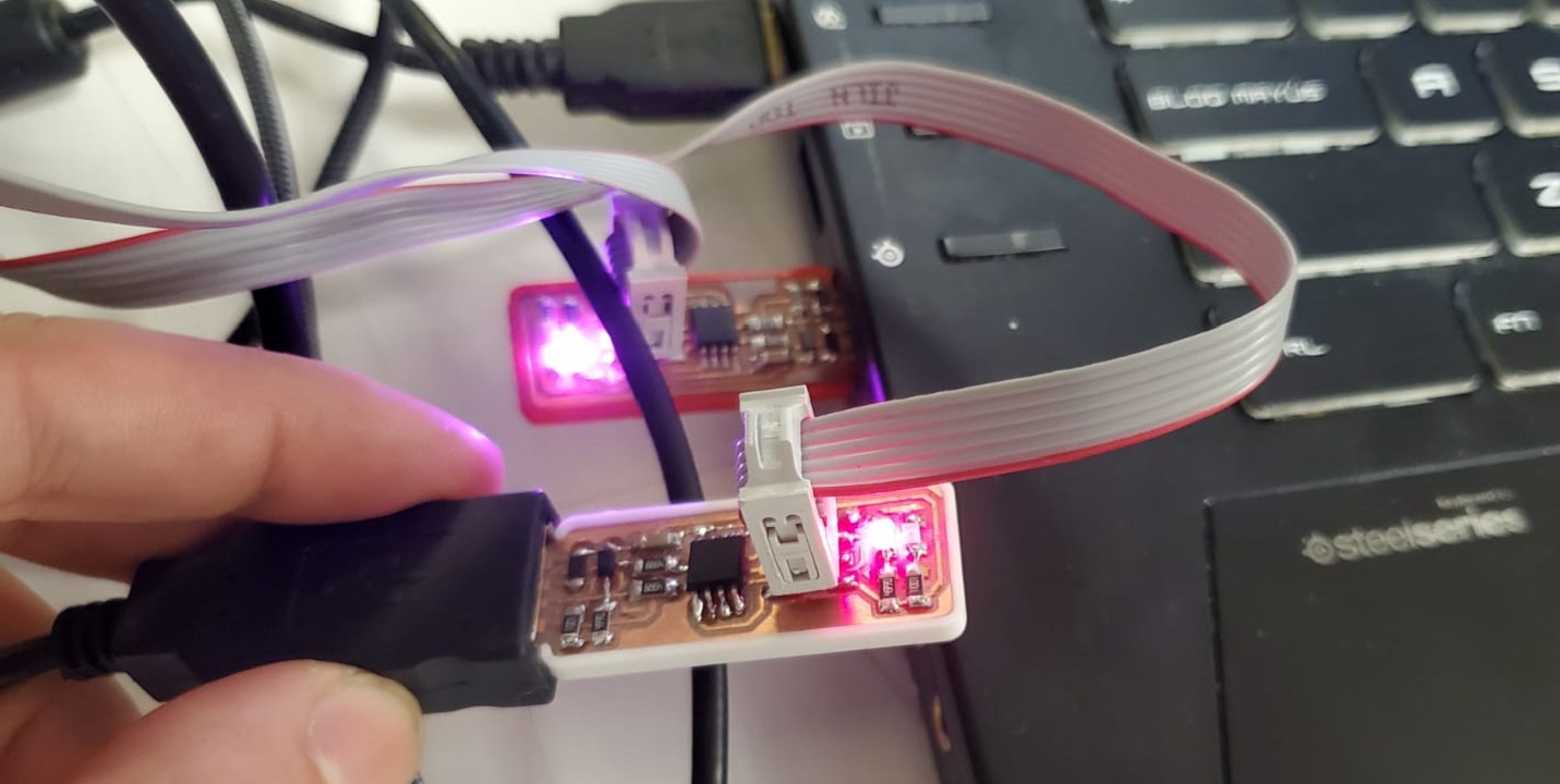
You can see that there's a white surrounding on my FabISP. More on that great addition later. If you have everything installed, check that it all works.
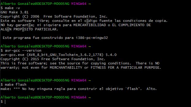
You can see there there's an error. I got that with the Voltera, but we will get to that later.
I run the Make Flash and then the Make Fuses, and everything went perfectly
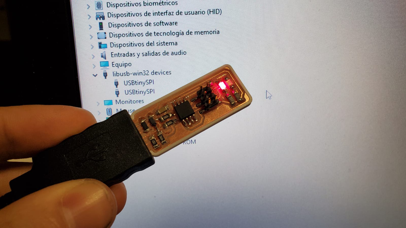
That white piece that surrounded my FabISP is like a case that other than protect the board, it gives it the necessary thickness to correctly plug it to a normal USB port. Sergio let me used his case for the programming and I found it super useful, so after the make fuses I gave him back his case and made a new one for my board. (in blue, because it looks better, of course). It's Adrian's design and you can find it here.
Chapter Two: the FabISP with Voltera V-One
The Voltera V-One is the new fighter in the world of PCB prototyping. However, How is it possible that I haven't found any documentation on creating a FabISP with it?
So, before you get too excited, I still haven't done it. I'm documenting my failures so you can laugh at me and hopefully one day I'll be able to just delete this part and be the first person ever to create the FabISP with the Voltera (or you may take it where I'm leaving it and you'll be the first one to achieve it). I have to say it does not look too promising for now
Step One: From PNG file to a PCB board
In order to design PCB boards, many people use kiCAD or Eagle. Both are software suites that facilitate the design of schematics for electronic circuits and their conversion to PCB boards. kiCAD is a free software and Eagle is an Autodesk product.
However, PCB boards are often made in FabLabs with a mini CNC mill, like a Roland Modela or a similar machine, and in order to share the files to machine the boards, PNG images are often used to save and send the file to the machine, so you can easily find many previous projects online as a .png. Moreover, it's a format that any computer can read, and many people can modify and then mill on a CCL (copper clad laminate) using a fairly common and fairly simple methodology, and send the code to the milling machine using FabModules or more recently Mods.
With the Voltera V-One, however, the old method is ditched, as you can almost only select gerber type files in Voltera's software, which will force you to design your own boards, to start from scratch, and you won’t be able to use the already existent open source projects as a base for new investigations.
But what if you could easily convert PNG files to Gerber type files, so you can create or modify a PNG in a very simple and user friendly software , that everyone can easily have Access to, like powerpoint, Gimp, Photoshop, or even Microsoft Paint?
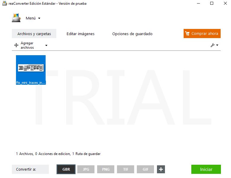
So here it comes reaConverter, which is a software with a free version that will allow us to convert a PNG image to a GBR file (Gerber). Be aware that this is an additive process, not substractive, so You'll need to invert the colors of the original file, as now black is white, and white is black.
So you just take your PNG file, convert it with the reaConverter from PNG to GBR, then open the Voltera software, choose the GBR file, press print, and then you only have to solder the components to the board that you’ve just printed. Result! Right? Well... WRONG!
We all wish it could be as simple as that, but in reality, it’s not. I’m going to go step by step showing you what I did, and the trouble I found.
First I tried Andy Bardagiy’s version, but actually, as my instructors told me that it was better to follow this other one .
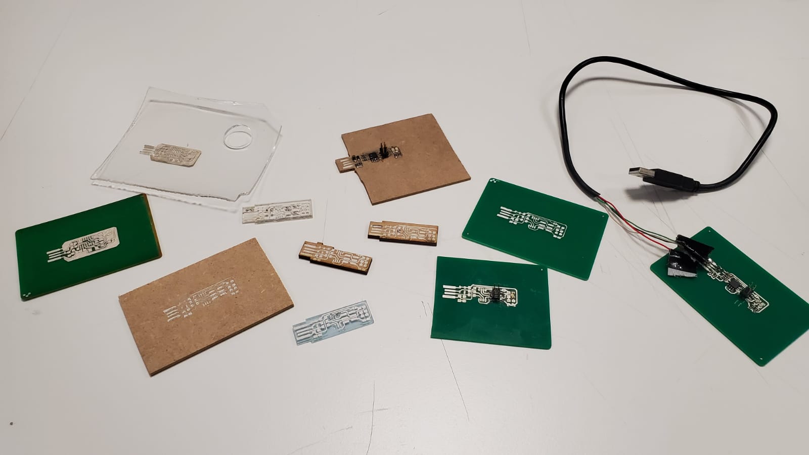
First of all, if we are going to create a FabISP without the need of the mill, then we need to print the board in a substrate than we can laser-cut later. We could use an FR4 substrate like the ones that come with the Voltera, but you can’t cut that in the laser, and the Wazer water cutter was not an option (we don’t have one yet), so I was forced to use other kinds of substrate. Let's get creative then.
December 2020. This is the first known (to me) FabISP test on Voltera. (Andy's version). The thing is, FR4 is made of fiberglass, so you can't actually make the USB connector shape without risks to your health... Let's see how we can solve this issue.
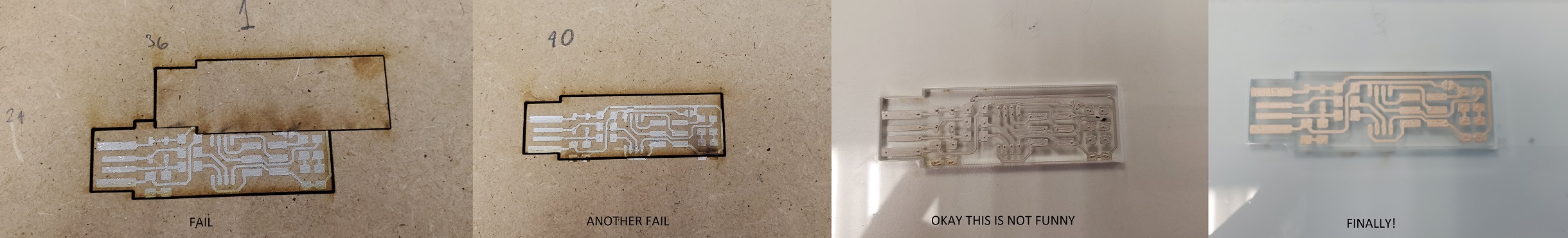
Step Two: Fail many times
One of the options we have is acrylic, but if you heat up the material (and you will, as you are initially supposed to bake the silver ink), the acrylic will bend.
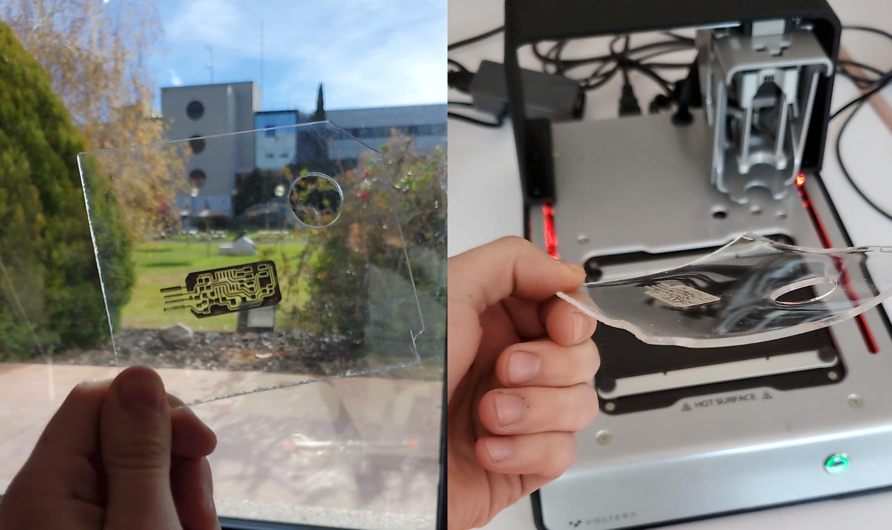
Two options now, you either let the board dry to the sunlight, or use another kind of substrate. So I did both (disclaimer: I'm now printing Brian's version of the FabISP instead of Andy's)
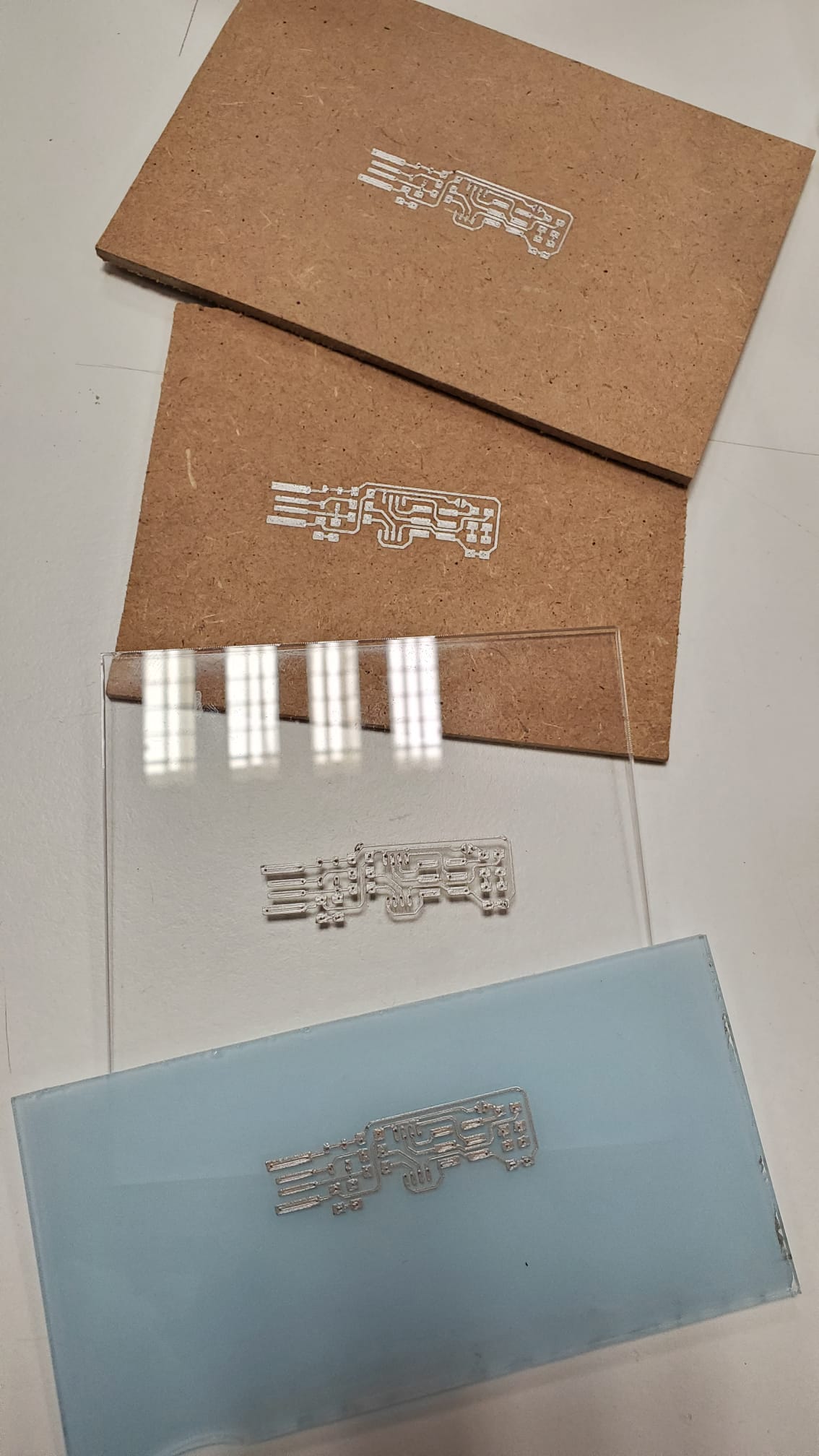
Okay, so now I have the boards. Can we laser cut them? Apparently, you should be very very careful when you measure the point where you want to cut, as I'll now illustrate:
At least I can have some boards to practice soldering, and then a board to actually build the FabISP in. Let's see what we can do.
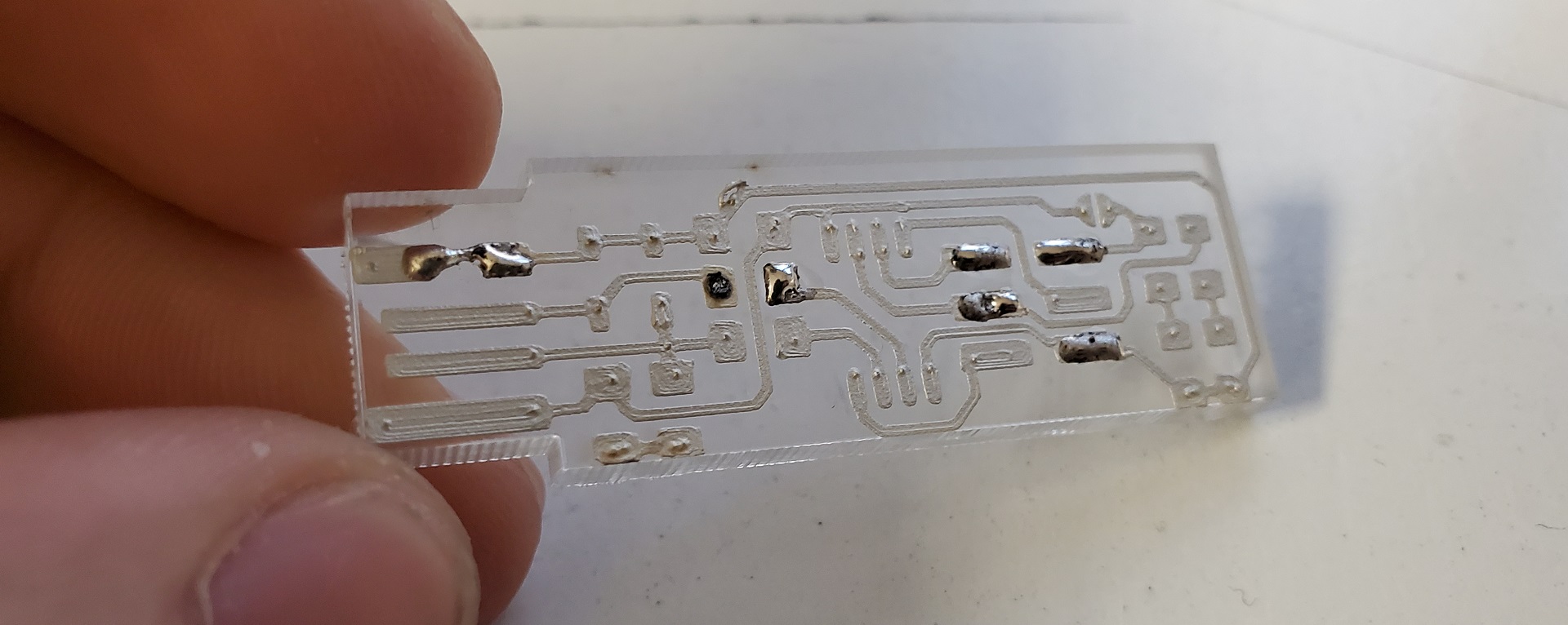
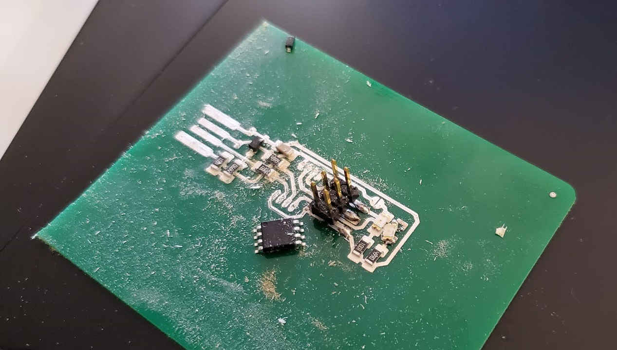
So as you can see, the solder takes away the track!. It's very very hard to solder in the big tracks, so this is what happened when I tried to solder the ATTINY to the board:
The track just disappeared!I'm going to blame it on the acrylic, so let's make another one out of wood.
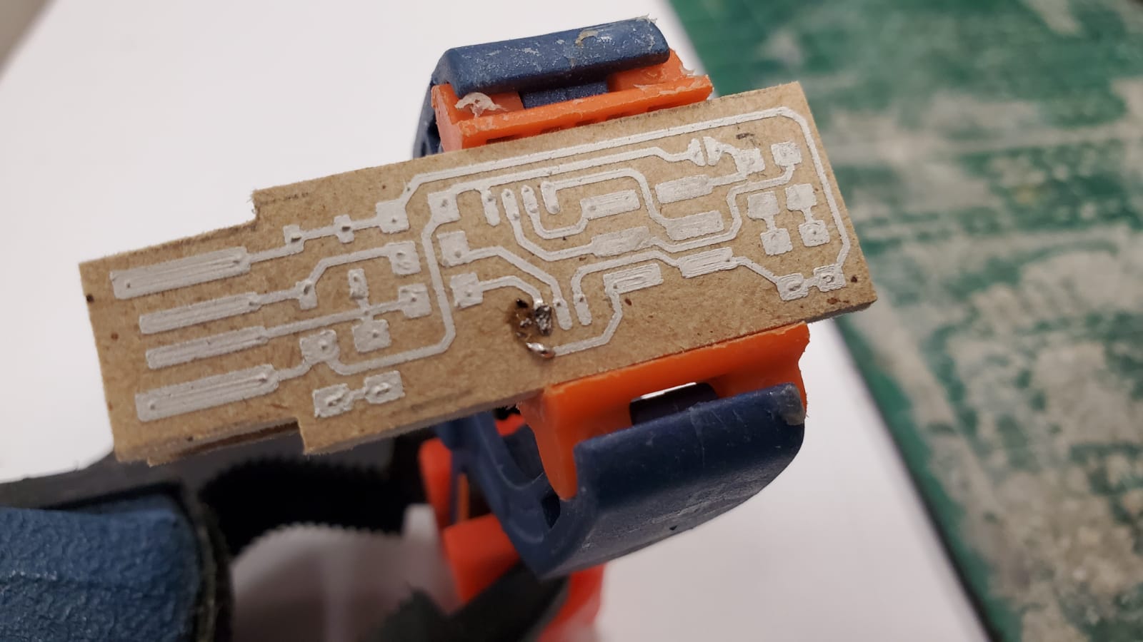
Oh, come on! So now I know I can't solder on the board if I don't cure it first. But hang on a second. What if I just place the electronic components on top of the fresh ink, and then use some non-conductive glue to make the union between the component and the board?
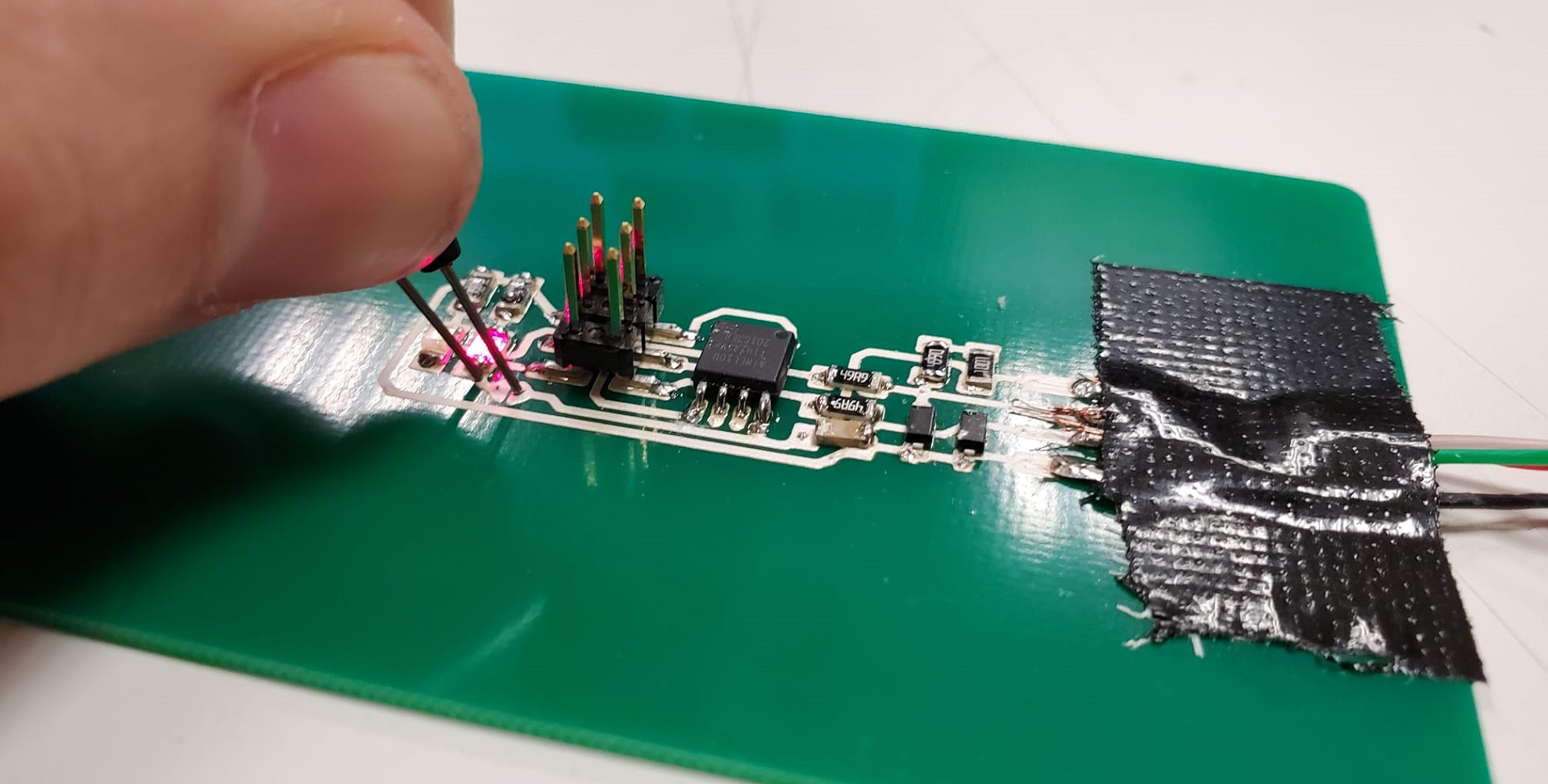
After cutting the USB bu hand with an electric saw, it was time to test it. Will I be able to program it?
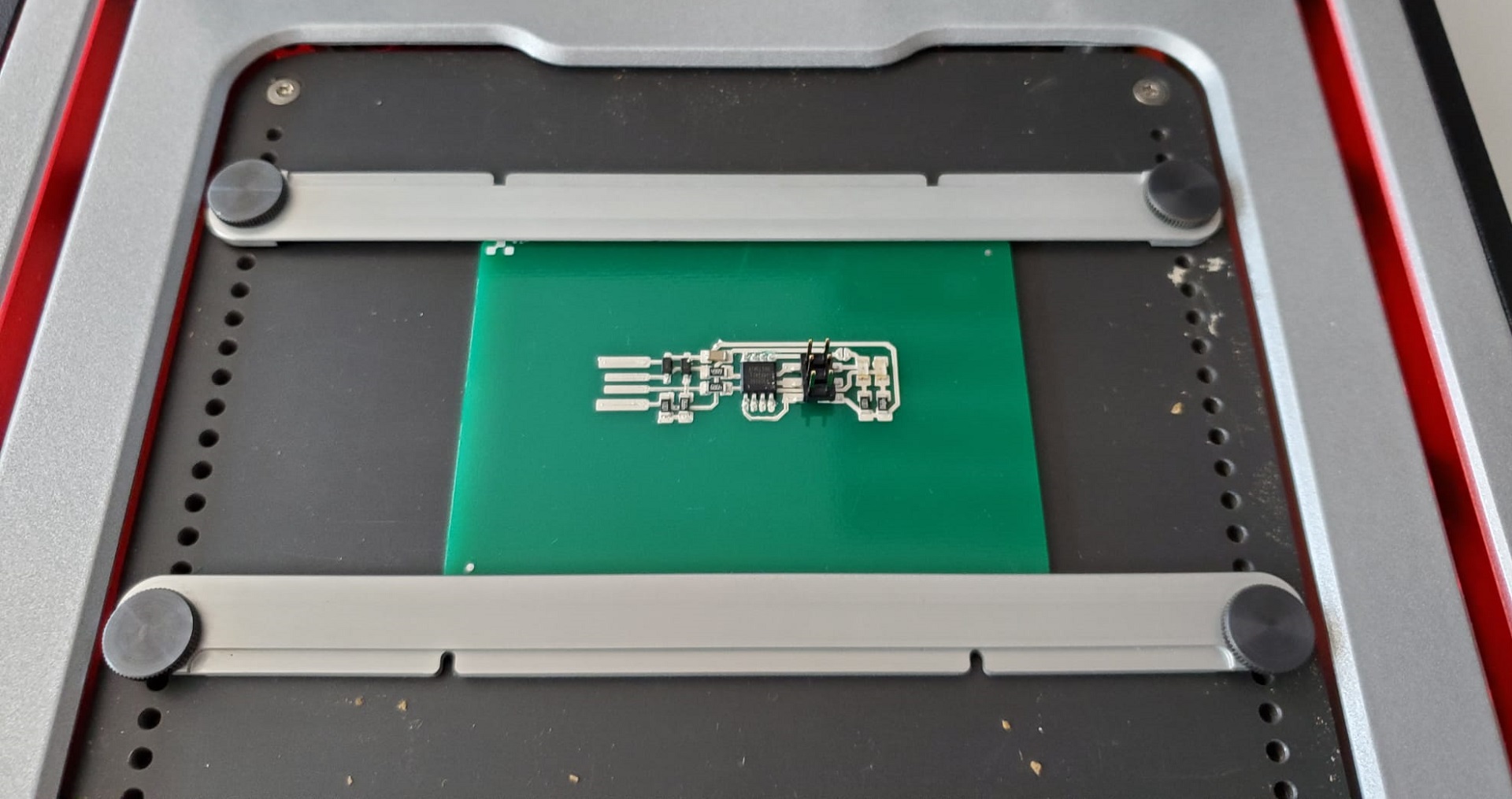
No! I can't! There must be some continuity error in the board. So back to the drawing board.. It would be great if I could just do the same but in the FR4 boards provided by the machine (you can solder in them easier) so I'm going to place the components now on a board, and then bake them. If there's a component I can feel it's not perfectly glued, I'm going to apply some soldering on them.
It was looking very promising. I was even willing to risk my health to try to cut the USB tip shape with the saw, I just wanted to plug it into my computer and see if it worked... And then, disaster! I tried to cut it and plug it straight in, I was running out of time, but the vibrations from the saw had other plans for my components. So after they flew away, it was time to start again...
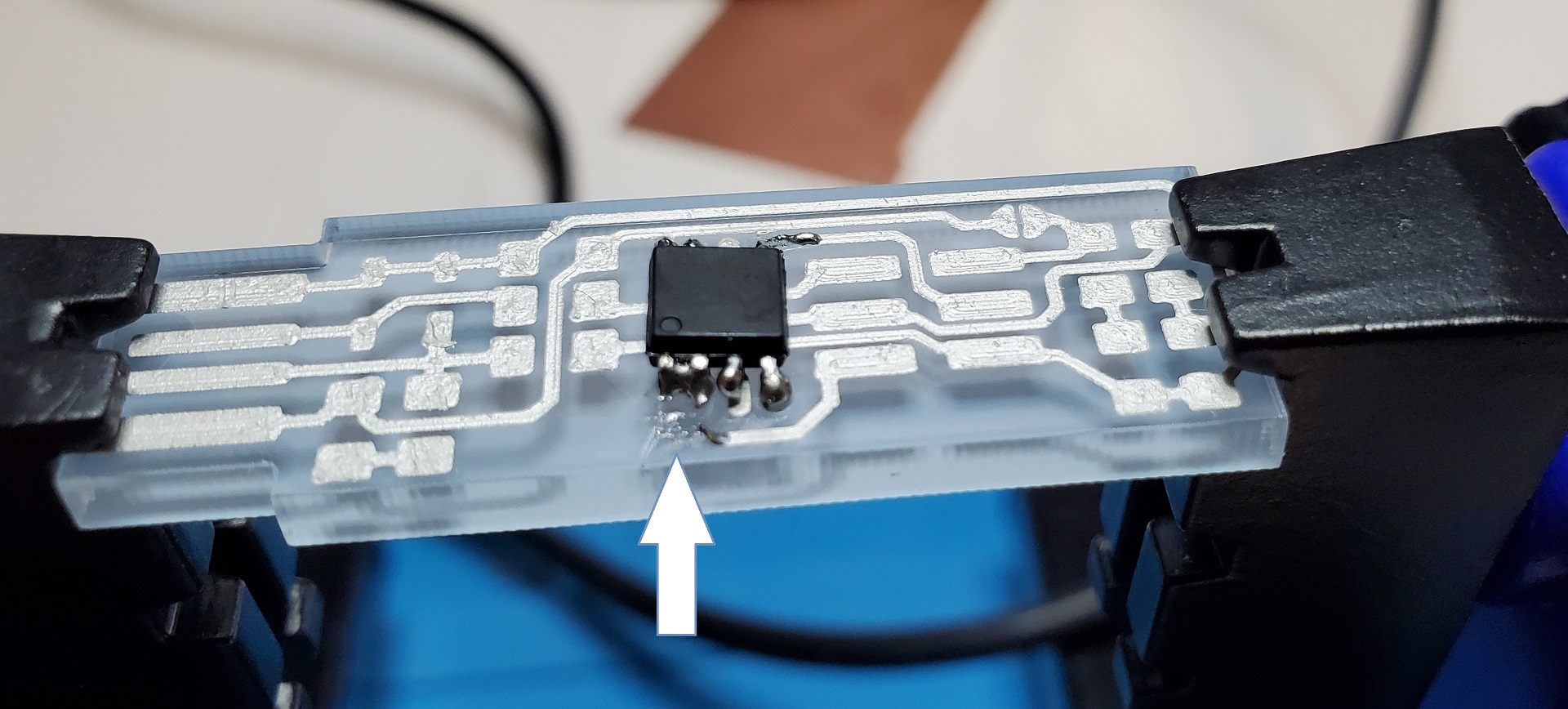
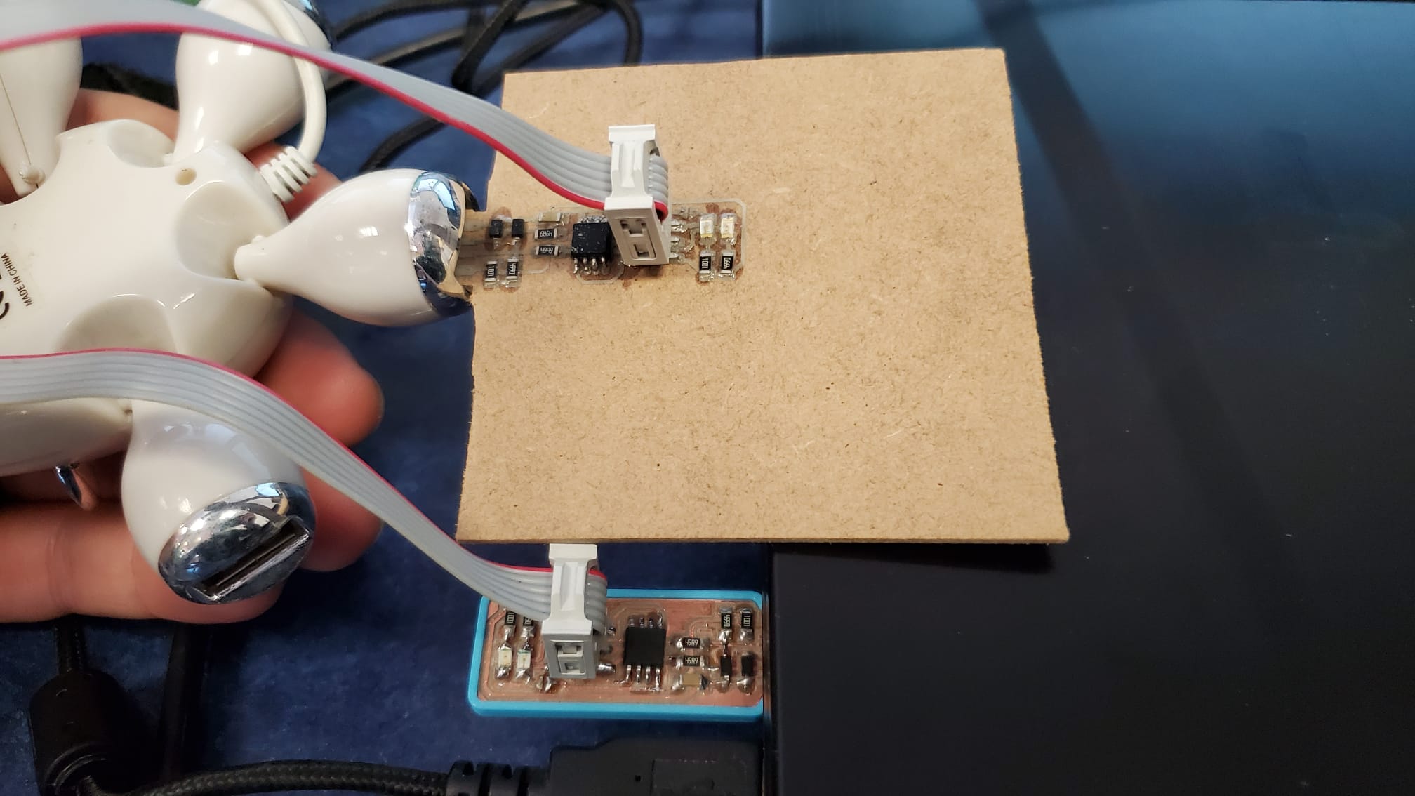
Let me introduce you to the new player in this class: The Voltera solder paste. The Voltera solder paste is another Voltera specific consumable item. Use it in the connection itself, then heat it up with the machine (it has that mode too). It has to be kept in the fridge, like the silver ink, and it's also very expensive. However, it saved my day. I placed the components (Thanks to my friend Javi Collado, who took me this great pic with the soldering paste). I heated the machine, so it cured the paste and became shiny and smooth.
Now I had another problem. I needed the USB, and I did not have it. FabLab Coordinators should be problem solvers, right? I had an old USB cable lying around, so I cut it and welded it to the board
Step Three: I almost had you
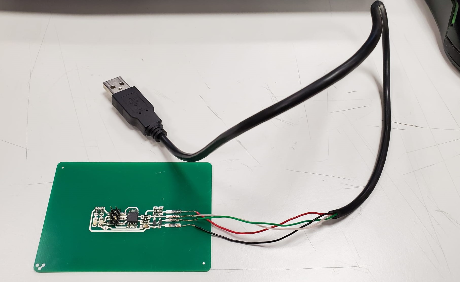
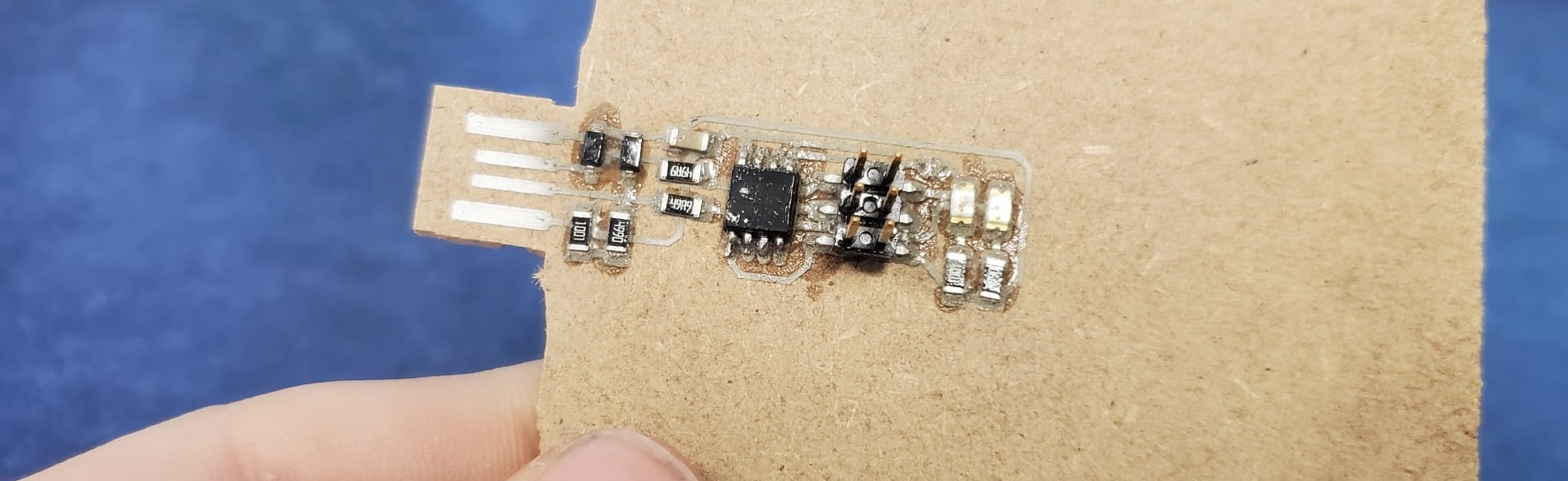
Now, the thing is that the "reset fuse" is opened, and knowing how sticky is Voltera ink to the board (very little) I decided that I was going to do the short circuit with a cable. So I isolated the cables from the USB, then I put the cable, and MAGIC! I did it! I had created a working FabISP with the Voltera!!!
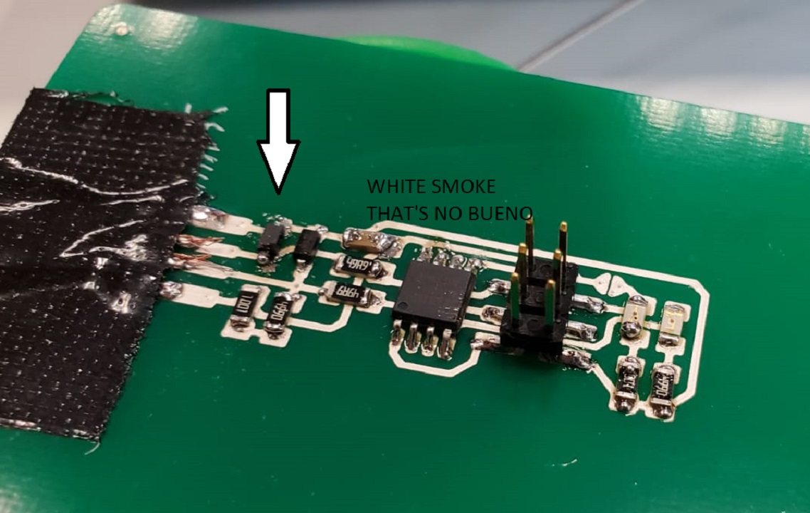
Welllllll... There was much rejoyce until I smelled something weird. There was a little bit of white smoke. I quickly realized that something was not working fine. My Zener diode was burnt. I thought it could be a Zener problem, so I changed the Zener. As soon as I put power back to the board, it happened again
So here it ends my Voltera VS Roland competition. I had only one failure with the Roland. But I had All of this failures with the Voltera!.
Group Assignment, part 1: How should I use the Roland then?
As we use the Roland with Fab Modules, I recommend to my future FabAcademy students to check the inventory of mills that we have in the lab. For the traces, with the 0.4 mm mill we mill at max rpm (15.000), then the speed at 3 mm/s and at a depth of 0.17 mm. For the outlines we have a 0.8 and a 1 mm mill, all of them spin at 15.000 rpm, and we mill at 2 mm/s in 0.3 mm steps until we cut all the way through the board.
With this configuration, the leveling problems that the bed may have are mitigated, and even if it's slow, it's very unlikely that you will break your endmill tip
Group Assignment, part 2: What is the Voltera actually made for?
The Voltera V-One is more precise than the Roland Modela mils,, in addition to what we already talked about: It's very intuitive to use, it can print, it can bake, it can drill, it can make double-sided boards with ease, and you can add lacquer and make multi-layer circuit boards
Professors Carlos Quiterio and Sergio Bemposta, with the students of the Electronics Club of the Universidad Europea showed me what they use the Voltera for. Many students prefer the Voltera over the Roland because they find it easier to work with. They create the circuits with kiCAD or Eagle and they send the Gerber files straight to the machine, and then follow the steps of the Voltera software. Failure is very very rare, it always works, and it's always very precise.
You can later use different kinds of electronics components to weld them on the rivets. So for that, we have to say, the Voltera works extremely well.
Would I recommend to buy the Voltera? If you are in an institution where it's very important to teach electronics to students, yes. Otherwise, if you need a board, have it prototyped on an external company or make it with the Roland mill. Another case were I would recommend buying it is that It can also print circuits on flexible materials like textile with its specific flexible conductive ink.If you end up buying the thing, get ready because It's really really expensive to run. Did I mention that you need to buy Voltera specific everything?
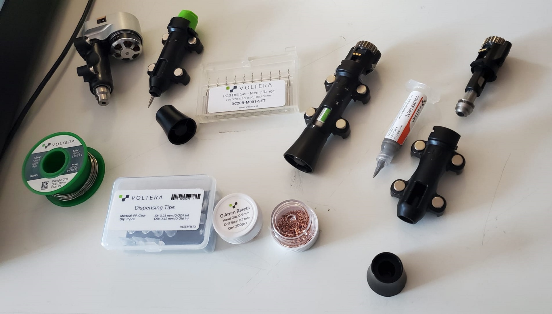
So, in the Voltera box we had the Voltera probe and the optional Voltera drill. We also got Voltera ink carriers and some conductive ink and solder paste. We also had some rivets and, some solder wire and some dispensing tips. Here's the problem: The solder wire is Voltera-specific, to be able to solder onto the conductive ink, that is also Voltera-specific (and expires in 6 months), or you can use the solder paste, that is also Voltera-specific (and also expires). You can buy the rivets from other companies, though. For the drill, you also have Voltera-specific endmills, but I think you can also get the mills from other companies. What you only can get from voltera are the dispensing tips. Those little plastic tips have a very little hole with a very tight tollerance. Ideally you should change it everytime you print.Solidified ink residues can stay in the tip and ruin the ink deposition. I've found that the best result is always achieved with the new dispensing tip, and that is, again, only available from Voltera.
Is it worth it, then? For a FabLab, I personally don't think it's worth it. But for a university, it absolutely is. And here in FabLab UE we give the service to the students mainly, so yeah, it's expensive, but I'm glad we got it.
Thank you so much for your attention, I hope to be able to investigate more with the Voltera, but it's over for this week. Let's git push this and have lunch, it's 8 in Boston but it's lunchtime in Spain. See you next week!
// // //