Mechanical Design and Machine Design
week 9 Group assignment is to design a machine that includes mechanism+actuation+automation - build the mechanical parts and operate it manually - document the group project and your individual contribution - actuate and automate your machine - document the group project and your individual contribution
Idea
After a long discussion which lasted almost two days we finlay decided to do a dual pen core x-y plotter cnc machine. I worked with many cnc project before core x-y is new to me but the still has many similar components that I have known . we spitted the whole project works for the 8 members team like Mechanical deign , FAbrication ,electronics,Firmware+UI .etc... I was in charge of the Electronics and the Firmware+UI for the firmware and the UI, Hanani B joined to with me

The above picture shows how it will be connected to the computer after everything done. the first two,G code executer Graphical Interface and the cnc controller are my individual part that I'm contributing to the group project
So from this above diagram the controller which controls the motors of the mechanical assembly is connected to the Computer via a serial communication port.There will be a User interface software which talk to the machine through the serial port by using some special codes that both the machine controller and the software understand , that is called G-Code. So the software will send the g code to the controller board and the controller will drive the motors accordingly
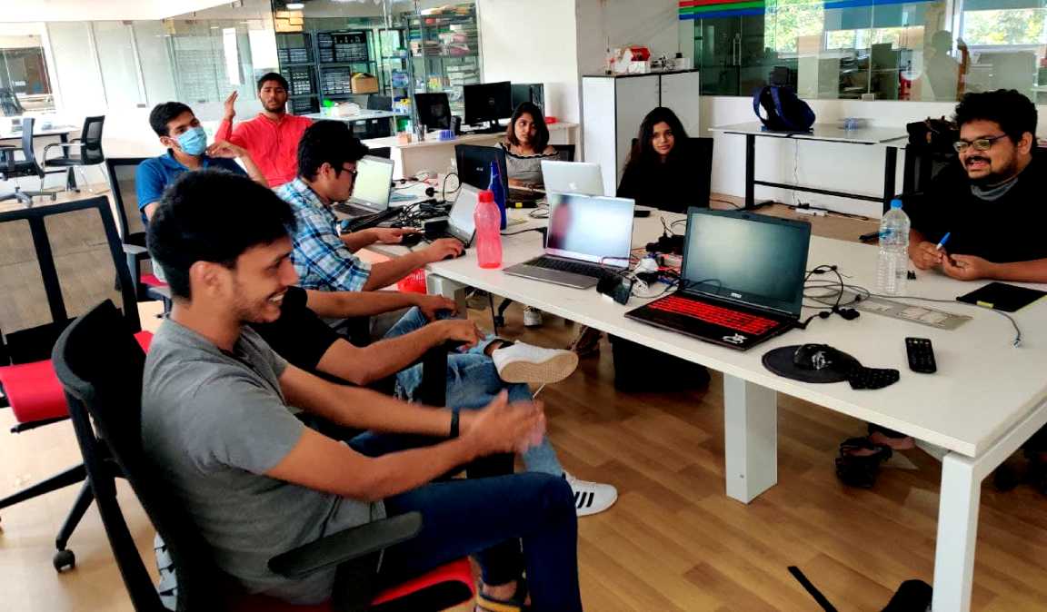
here is a picture taken by Abhinav during our Brain storming discussion you can see that I'm over exited in the picture.
Research
While the mechanical team was busy we decided to set the firmware with required electronics .I made a functional block diagram and explained to the whole team what I'm about to do
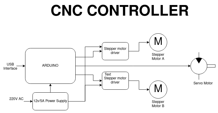
The above picture shows the functional block diagram of electronics components that we are using in this group project. The cnc controller that we Used is an arduino Board.Because its easy to set up lot of tutorials available and lot of firmwares too .the electronics is pretty simple. everything available in the lab as modular modules.
Components Required
- 1.Arduino UNO x1
- 2.CNC Shield V3
- 3.A4988 Stepper Drivers x2
- 4.NEMA17 Stepper Motor x2
- 5.Servo motor (0-180 deg) x1
- 6.12v 5A Power Supply
Those are the required components for setting up the controller unit of the cnc But in FAB LAB Kerala we don't have all of them in the lab.so we decided to go with what the lab can provide. Instead of the Arduino UNO with CNC Shield lab has Arduino MEGA with Ramps Shield.It's ok any way its more than requires the Ramps Shield mainly used as 3D Printer's Control board.It can support 5 stepper driver .We only need two
- 1.Arduino MEGA x1
- 2.Ramps 1.4 Shield
- 3.A4988 Stepper Drivers x2
- 4.NEMA17 Stepper Motor x2
- 5.Servo motor (0-180 deg) x1
- 6.12v 5A Power Supply
We collected above components from the lab and tested by running a basic stepper arduino code and we found out the all A4988 driver available in the lab is not working
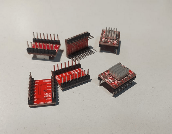
These are cheap chinese clone A4988 modules mostly fried out already.the chances of frying these type of stepper motor during projects are high luckily Fablab kochi has another type of stepper motor driver called DRV8825
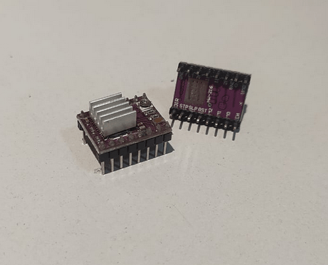
Then we assembled everything.Assembling is very easy just like add-on cards of computers
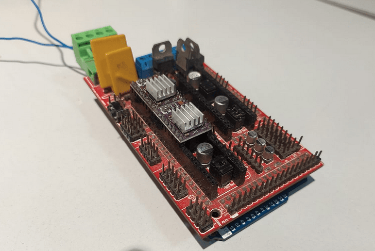
The machine that we are building wasn't ready for electronics because it was not made that time so we desired to use an older mechanical x,y machine built by some visiters from other fab lab.
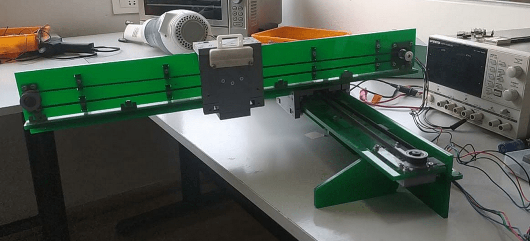
this machine was made based on the design by Jake Read. Nicely done design we found this mechanical part from our Fablab without the controller. Our first mission is to understand the firmware and if possible build one our own
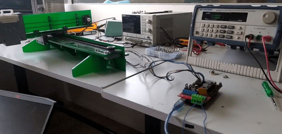
We hooked up the x and y stepper motors to the control board and tested with a stepper motor library example called AcceleStepper I worked with this library before very easy to use with arduino.we used the lab power supply as the power source set to 12v and the motor driver programed as 1/16 micro stepping using the on board jumper of the Ramps shield
From the test we understand it moves each axis individually x,y or -x,-y directions.u can sse that from above video.but we want synchronized motion of both axis
CODE :-
                #include < AccelStepper.h>

                    #define dirPin A1
                    #define dirPin2 A7

                    #define stepPin A0
                    #define stepPin2 A6

                    #define motorInterfaceType 1
                    AccelStepper stepper = AccelStepper(motorInterfaceType, stepPin, dirPin);
                    AccelStepper stepper2 = AccelStepper(motorInterfaceType, stepPin2, dirPin2);

                    int rslu = 0.1;
                    void setup() {
                      Serial.begin(9600);
                      pinMode(A2,OUTPUT);
                      pinMode(38,OUTPUT);
                     stepper.setMaxSpeed(4000);
                      stepper.setAcceleration(5000);
                      stepper.setCurrentPosition(0);
                       stepper2.setMaxSpeed(4000);
                      stepper2.setAcceleration(5000);
                      stepper2.setCurrentPosition(0);
                     digitalWrite(38,LOW);
                     digitalWrite(A2,LOW);
                    }

                    void loop() {
                    mov(53000);
                    mov2(20000);
                    mov(-53000);
                    mov2(-20000)

                    }
                    void mov (long int l)
                    {
                      stepper.setCurrentPosition(0);
                      long int stp =  l;
                      //  stepper.setSpeed(5000);

                      stepper.moveTo(stp);
                      stepper.runToPosition();
                      Serial.println(stp);
                      Serial.println(stepper.currentPosition());

                    }
                    void mov2 (long int l)
                    {
                      stepper2.setCurrentPosition(0);
                      long int stp =  l;
                      //  stepper.setSpeed(5000);

                      stepper2.moveTo(stp);
                      stepper2.runToPosition();
                      Serial.println(stp);
                      Serial.println(stepper2.currentPosition());

                    }
Using AcceleStepper library some one modified for multisteppers to work them synchronously.and it can support upto 10 motors ata a time so we found the code on arduino examples and modified for us and tested it out
This time it worked as we expected,It calculate both distance and time to reach then shortest one will go at lower speed largest distance will be higher than the other axis.The code is given below
CODE :-
                    // MultiStepper.pde
                    // -*- mode: C++ -*-
                    // Use MultiStepper class to manage multiple steppers and make them all move to
                    // the same position at the same time for linear 2d (or 3d) motion.

                    #include < AccelStepper.h>
                    #include < MultiStepper.h>

                    // EG X-Y position bed driven by 2 steppers
                    // Alas its not possible to build an array of these with different pins for each :-(
                    AccelStepper stepper1(AccelStepper::DRIVER, A0,A1);
                    AccelStepper stepper2(AccelStepper::DRIVER, A6,A7);

                    // Up to 10 steppers can be handled as a group by MultiStepper
                    MultiStepper steppers;
                      long positions[2]; // Array of desired stepper positions

                    void setup() {
                      Serial.begin(9600);
                     pinMode(A2,OUTPUT);
                      pinMode(38,OUTPUT);
                      // Configure each stepper
                     stepper1.setMaxSpeed(40000);
                      stepper1.setAcceleration(5000);
                      stepper1.setCurrentPosition(0);
                       stepper2.setMaxSpeed(40000);
                      stepper2.setAcceleration(5000);
                      stepper2.setCurrentPosition(0);

                      // Then give them to MultiStepper to manage
                      steppers.addStepper(stepper1);
                      steppers.addStepper(stepper2);
                      digitalWrite(38,LOW);
                     digitalWrite(A2,LOW);
                    }

                    void loop() {
                      mov(10000,10000);
                       mov(-10000,10000);
                        mov(-10000,-10000);
                         mov(10000,-10000);

                    }
                    void mov(long x,long y){
                      positions[0] = x+y;
                      positions[1] = x-y;
                      steppers.moveTo(positions);
                      steppers.runSpeedToPosition(); // Blocks until all are in position
                    //    stepper2.setCurrentPosition(0);
                    //      stepper1.setCurrentPosition(0);
                    }
The Firmware
After the testing we tried to understand how the whole cnc firmware works to make one our own . we get that 'It only drives the motors according to the g code instruction which is given by serial ports'. so we need a program which can receive the serial data and identify the g code then drive the motors to the co-ordinate given line by line in the g code
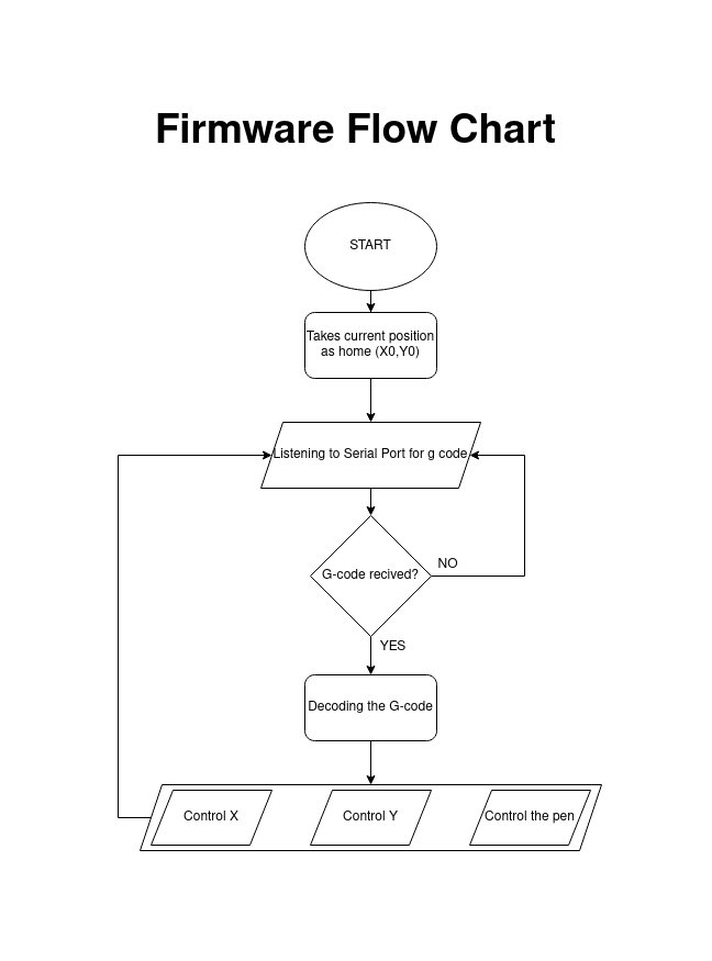
The above diagram is a flow chart of working structure of the firmware which we understand .we already got an basic firmware which is not using same motors and components we use but the g code is universal . so we decided to edit it we read all the code and understand how it works.The code is given below
Basic Firmware CODE :-
#include < Servo.h>
#include < Stepper.h>
#define LINE_BUFFER_LENGTH 512
const int penZUp = 40;
const int penZDown = 80;
const int penServoPin = 6;
const int stepsPerRevolution = 60;
Servo penServo;
Stepper myStepperY(stepsPerRevolution, 5,3,4,2);
Stepper myStepperX(stepsPerRevolution, 11,9,10,8);
struct point {
float x;
float y;
float z;
};
struct point actuatorPos;
float StepInc = 1;
int StepDelay = 0;
int LineDelay = 50;
int penDelay = 50;
float StepsPerMillimeterX = 100.0;
float StepsPerMillimeterY = 100.0;
float Xmin = 0;
float Xmax = 100;
float Ymin = 0;
float Ymax = 100;
float Zmin = 0;
float Zmax = 1;
float Xpos = Xmin;
float Ypos = Ymin;
float Zpos = Zmax;
boolean verbose = false;
void setup() {
Serial.begin( 9600 );
penServo.attach(penServoPin);
penServo.write(penZUp);
delay(200);
myStepperX.setSpeed(200);
myStepperY.setSpeed(200);
Serial.println("Mini CNC Plotter alive and kicking!");
Serial.print("X range is from ");
Serial.print(Xmin);
Serial.print(" to ");
Serial.print(Xmax);
Serial.println(" mm.");
Serial.print("Y range is from ");
Serial.print(Ymin);
Serial.print(" to ");
Serial.print(Ymax);
Serial.println(" mm.");
}
void loop()
{
delay(200);
char line[ LINE_BUFFER_LENGTH ];
char c;
int lineIndex;
bool lineIsComment, lineSemiColon;
lineIndex = 0;
lineSemiColon = false;
lineIsComment = false;
while (1) {
while ( Serial.available()>0 ) {
c = Serial.read();
if (( c == '\n') || (c == '\r') ) {
if ( lineIndex > 0 ) {
line[ lineIndex ] = '\0';
if (verbose) {
Serial.print( "Received : ");
Serial.println( line );
}
processIncomingLine( line, lineIndex );
lineIndex = 0;
}
else {
}
lineIsComment = false;
lineSemiColon = false;
Serial.println("ok");
}
else {
if ( (lineIsComment) || (lineSemiColon) ) { // Throw away all comment characters
if ( c == ')' ) lineIsComment = false; // End of comment. Resume line.
}
else {
if ( c <= ' ' ) { // Throw away whitepace and control characters
}
else if ( c == '/' ) { // Block delete not supported. Ignore character.
}
else if ( c == '(' ) { // Enable comments flag and ignore all characters until ')' or EOL.
lineIsComment = true;
}
else if ( c == ';' ) {
lineSemiColon = true;
}
else if ( lineIndex >= LINE_BUFFER_LENGTH-1 ) {
Serial.println( "ERROR - lineBuffer overflow" );
lineIsComment = false;
lineSemiColon = false;
}
else if ( c >= 'a' && c <= 'z' ) { // Upcase lowercase
line[ lineIndex++ ] = c-'a'+'A';
}
else {
line[ lineIndex++ ] = c;
}
}
}
}
}
}
void processIncomingLine( char* line, int charNB ) {
int currentIndex = 0;
char buffer[ 64 ]; // Hope that 64 is enough for 1 parameter
struct point newPos;
newPos.x = 0.0;
newPos.y = 0.0;
// Needs to interpret
// G1 for moving
// G4 P300 (wait 150ms)
// G1 X60 Y30
// G1 X30 Y50
// M300 S30 (pen down)
// M300 S50 (pen up)
// Discard anything with a (
// Discard any other command!
while( currentIndex < charNB ) {
switch ( line[ currentIndex++ ] ) { // Select command, if any
case 'U':
penUp();
break;
case 'D':
penDown();
break;
case 'G':
buffer[0] = line[ currentIndex++ ]; // /!\ Dirty - Only works with 2 digit commands
// buffer[1] = line[ currentIndex++ ];
// buffer[2] = '\0';
buffer[1] = '\0';
switch ( atoi( buffer ) ){ // Select G command
case 0: // G00 & G01 - Movement or fast movement. Same here
case 1:
// /!\ Dirty - Suppose that X is before Y
char* indexX = strchr( line+currentIndex, 'X' ); // Get X/Y position in the string (if any)
char* indexY = strchr( line+currentIndex, 'Y' );
if ( indexY <= 0 ) {
newPos.x = atof( indexX + 1);
newPos.y = actuatorPos.y;
}
else if ( indexX <= 0 ) {
newPos.y = atof( indexY + 1);
newPos.x = actuatorPos.x;
}
else {
newPos.y = atof( indexY + 1);
indexY = '\0';
newPos.x = atof( indexX + 1);
}
drawLine(newPos.x, newPos.y );
// Serial.println("ok");
actuatorPos.x = newPos.x;
actuatorPos.y = newPos.y;
break;
}
break;
case 'M':
buffer[0] = line[ currentIndex++ ]; // /!\ Dirty - Only works with 3 digit commands
buffer[1] = line[ currentIndex++ ];
buffer[2] = line[ currentIndex++ ];
buffer[3] = '\0';
switch ( atoi( buffer ) ){
case 300:
{
char* indexS = strchr( line+currentIndex, 'S' );
float Spos = atof( indexS + 1);
// Serial.println("ok");
if (Spos == 30) {
penDown();
}
if (Spos == 50) {
penUp();
}
break;
}
case 114: // M114 - Repport position
Serial.print( "Absolute position : X = " );
Serial.print( actuatorPos.x );
Serial.print( " - Y = " );
Serial.println( actuatorPos.y );
break;
default:
Serial.print( "Command not recognized : M");
Serial.println( buffer );
}
}
}
}
void drawLine(float x1, float y1) {
if (verbose)
{
Serial.print("fx1, fy1: ");
Serial.print(x1);
Serial.print(",");
Serial.print(y1);
Serial.println("");
}
if (x1 >= Xmax) {
x1 = Xmax;
}
if (x1 <= Xmin) {
x1 = Xmin;
}
if (y1 >= Ymax) {
y1 = Ymax;
}
if (y1 <= Ymin) {
y1 = Ymin;
}
if (verbose)
{
Serial.print("Xpos, Ypos: ");
Serial.print(Xpos);
Serial.print(",");
Serial.print(Ypos);
Serial.println("");
}
if (verbose)
{
Serial.print("x1, y1: ");
Serial.print(x1);
Serial.print(",");
Serial.print(y1);
Serial.println("");
}
// Convert coordinates to steps
x1 = (int)(x1*StepsPerMillimeterX);
y1 = (int)(y1*StepsPerMillimeterY);
float x0 = Xpos;
float y0 = Ypos;
// Let's find out the change for the coordinates
long dx = abs(x1-x0);
long dy = abs(y1-y0);
int sx = x0< x1 ? StepInc : -StepInc;
int sy = y0< y1 ? StepInc : -StepInc;
long i;
long over = 0;
if (dx > dy) {
for (i=0; i=dx) {
over-=dx;
myStepperY.step(sy);
}
delay(StepDelay);
}
}
else {
for (i=0; i=dy) {
over-=dy;
myStepperX.step(sx);
}
delay(StepDelay);
}
}
if (verbose)
{
Serial.print("dx, dy:");
Serial.print(dx);
Serial.print(",");
Serial.print(dy);
Serial.println("");
}
if (verbose)
{
Serial.print("Going to (");
Serial.print(x0);
Serial.print(",");
Serial.print(y0);
Serial.println(")");
}
delay(LineDelay);
Xpos = x1;
Ypos = y1;
}
void penUp() {
penServo.write(penZUp);
delay(LineDelay);
Zpos=Zmax;
if (verbose) {
Serial.println("Pen up!");
}
}
void penDown() {
penServo.write(penZDown);
delay(LineDelay);
Zpos=Zmin;
if (verbose) {
Serial.println("Pen down.");
}
}
We found the motor coordinates function in the code replaced with ours which made by using 'AcceleStepper.h' library
Edited Firmware CODE :-
#include < Servo.h>
//#include < Stepper.h>
#include < AccelStepper.h>
#include < MultiStepper.h>
AccelStepper stepper1(AccelStepper::DRIVER, A0,A1);
AccelStepper stepper2(AccelStepper::DRIVER, A6,A7);
MultiStepper steppers;
#define LINE_BUFFER_LENGTH 512
const int penZUp = 40;
const int penZDown = 80;
const int penServoPin = 6;
const int stepsPerRevolution = 60;
Servo penServo;
//
//Stepper myStepperY(stepsPerRevolution, 5,3,4,2);
//Stepper myStepperX(stepsPerRevolution, 11,9,10,8);
struct point {
float x;
float y;
float z;
};
struct point actuatorPos;
float StepInc = 1;
int StepDelay = 0;
int LineDelay = 50;
int penDelay = 50;
float StepsPerMillimeterX = 160.0;
float StepsPerMillimeterY = 160.0;
float Xmin = 0;
float Xmax = 100;
float Ymin = 0;
float Ymax = 100;
float Zmin = 0;
float Zmax = 1;
float Xpos = Xmin;
float Ypos = Ymin;
float Zpos = Zmax;
boolean verbose = true;
long positions[2]; // Array of desired stepper positions
void setup() {
Serial.begin( 9600 );
pinMode(A2,OUTPUT);
pinMode(38,OUTPUT);
// Configure each stepper
stepper1.setMaxSpeed(4000);
stepper1.setAcceleration(5000);
stepper1.setCurrentPosition(0);
stepper2.setMaxSpeed(4000);
stepper2.setAcceleration(5000);
stepper2.setCurrentPosition(0);
steppers.addStepper(stepper1);
steppers.addStepper(stepper2);
digitalWrite(38,LOW);
digitalWrite(A2,LOW);
penServo.attach(penServoPin);
penServo.write(penZUp);
delay(200);
// myStepperX.setSpeed(200);
// myStepperY.setSpeed(200);
Serial.println("Mini CNC Plotter alive and kicking!");
Serial.print("X range is from ");
Serial.print(Xmin);
Serial.print(" to ");
Serial.print(Xmax);
Serial.println(" mm.");
Serial.print("Y range is from ");
Serial.print(Ymin);
Serial.print(" to ");
Serial.print(Ymax);
Serial.println(" mm.");
}
void loop()
{
delay(200);
char line[ LINE_BUFFER_LENGTH ];
char c;
int lineIndex;
bool lineIsComment, lineSemiColon;
lineIndex = 0;
lineSemiColon = false;
lineIsComment = false;
while (1) {
while ( Serial.available()>0 ) {
c = Serial.read();
if (( c == '\n') || (c == '\r') ) {
if ( lineIndex > 0 ) {
line[ lineIndex ] = '\0';
if (verbose) {
Serial.print( "Received : ");
Serial.println( line );
}
processIncomingLine( line, lineIndex );
lineIndex = 0;
}
else {
}
lineIsComment = false;
lineSemiColon = false;
Serial.println("ok");
}
else {
if ( (lineIsComment) || (lineSemiColon) ) { // Throw away all comment characters
if ( c == ')' ) lineIsComment = false; // End of comment. Resume line.
}
else {
if ( c <= ' ' ) { // Throw away whitepace and control characters
}
else if ( c == '/' ) { // Block delete not supported. Ignore character.
}
else if ( c == '(' ) { // Enable comments flag and ignore all characters until ')' or EOL.
lineIsComment = true;
}
else if ( c == ';' ) {
lineSemiColon = true;
}
else if ( lineIndex >= LINE_BUFFER_LENGTH-1 ) {
Serial.println( "ERROR - lineBuffer overflow" );
lineIsComment = false;
lineSemiColon = false;
}
else if ( c >= 'a' && c <= 'z' ) { // Upcase lowercase
line[ lineIndex++ ] = c-'a'+'A';
}
else {
line[ lineIndex++ ] = c;
}
}
}
}
}
}
void processIncomingLine( char* line, int charNB ) {
int currentIndex = 0;
char buffer[ 64 ]; // Hope that 64 is enough for 1 parameter
struct point newPos;
newPos.x = 0.0;
newPos.y = 0.0;
// Needs to interpret
// G1 for moving
// G4 P300 (wait 150ms)
// G1 X60 Y30
// G1 X30 Y50
// M300 S30 (pen down)
// M300 S50 (pen up)
// Discard anything with a (
// Discard any other command!
while( currentIndex < charNB ) {
switch ( line[ currentIndex++ ] ) { // Select command, if any
case 'U':
penUp();
break;
case 'D':
penDown();
break;
case 'G':
buffer[0] = line[ currentIndex++ ]; // /!\ Dirty - Only works with 2 digit commands
// buffer[1] = line[ currentIndex++ ];
// buffer[2] = '\0';
buffer[1] = '\0';
switch ( atoi( buffer ) ){ // Select G command
case 0: // G00 & G01 - Movement or fast movement. Same here
case 1:
// /!\ Dirty - Suppose that X is before Y
char* indexX = strchr( line+currentIndex, 'X' ); // Get X/Y position in the string (if any)
char* indexY = strchr( line+currentIndex, 'Y' );
if ( indexY <= 0 ) {
newPos.x = atof( indexX + 1);
newPos.y = actuatorPos.y;
}
else if ( indexX <= 0 ) {
newPos.y = atof( indexY + 1);
newPos.x = actuatorPos.x;
}
else {
newPos.y = atof( indexY + 1);
indexY = '\0';
newPos.x = atof( indexX + 1);
}
drawLine(newPos.x, newPos.y );
// Serial.println("ok");
actuatorPos.x = newPos.x;
actuatorPos.y = newPos.y;
break;
}
break;
case 'M':
buffer[0] = line[ currentIndex++ ]; // /!\ Dirty - Only works with 3 digit commands
buffer[1] = line[ currentIndex++ ];
buffer[2] = line[ currentIndex++ ];
buffer[3] = '\0';
switch ( atoi( buffer ) ){
case 300:
{
char* indexS = strchr( line+currentIndex, 'S' );
float Spos = atof( indexS + 1);
// Serial.println("ok");
if (Spos == 30) {
penDown();
}
if (Spos == 50) {
penUp();
}
break;
}
case 114: // M114 - Repport position
Serial.print( "Absolute position : X = " );
Serial.print( actuatorPos.x );
Serial.print( " - Y = " );
Serial.println( actuatorPos.y );
break;
default:
Serial.print( "Command not recognized : M");
Serial.println( buffer );
}
}
}
}
void drawLine(float x1, float y1) {
if (verbose)
{
Serial.print("fx1, fy1: ");
Serial.print(x1);
Serial.print(",");
Serial.print(y1);
Serial.println("");
}
if (x1 >= Xmax) {
x1 = Xmax;
}
if (x1 <= Xmin) {
x1 = Xmin;
}
if (y1 >= Ymax) {
y1 = Ymax;
}
if (y1 <= Ymin) {
y1 = Ymin;
}
if (verbose)
{
Serial.print("Xpos, Ypos: ");
Serial.print(Xpos);
Serial.print(",");
Serial.print(Ypos);
Serial.println("");
}
if (verbose)
{
Serial.print("x1, y1: ");
Serial.print(x1);
Serial.print(",");
Serial.print(y1);
Serial.println("");
}
// Convert coordinates to steps
x1 = (int)(x1*StepsPerMillimeterX);
y1 = (int)(y1*StepsPerMillimeterY);
mov(x1,y1);// sending the co-ordinates
float x0 = Xpos;
float y0 = Ypos;
// Let's find out the change for the coordinates
long dx = abs(x1-x0);
long dy = abs(y1-y0);
int sx = x0< x1 ? StepInc : -StepInc;
int sy = y0< y1 ? StepInc : -StepInc;
long i;
long over = 0;
if (dx > dy) {
for (i=0; i< dx; ++i) {
// Serial.print("x:");
// Serial.println(sx);
// myStepperX.step(sx);
over+=dy;
if (over>=dx) {
over-=dx;
// Serial.print("y:");
// Serial.println(sy);
// myStepperY.step(sy);
}
delay(StepDelay);
}
}
else {
for (i=0; i< dy; ++i) {
// Serial.print("y:");
// Serial.println(sy);
// myStepperY.step(sy);
over+=dx;
if (over>=dy) {
over-=dy;
// Serial.print("x:");
// Serial.println(sx);
// myStepperX.step(sx);
}
delay(StepDelay);
}
}
if (verbose)
{
Serial.print("dx, dy:");
Serial.print(dx);
Serial.print(",");
Serial.print(dy);
Serial.println("");
}
if (verbose)
{
Serial.print("Going to (");
Serial.print(x0);
Serial.print(",");
Serial.print(y0);
Serial.println(")");
}
delay(LineDelay);
Xpos = x1;
Ypos = y1;
}
void penUp() {
penServo.write(penZUp);
delay(LineDelay);
Zpos=Zmax;
if (verbose) {
Serial.println("Pen up!");
}
}
void penDown() {
penServo.write(penZDown);
delay(LineDelay);
Zpos=Zmin;
if (verbose) {
Serial.println("Pen down.");
}
}
void mov(long x,long y){
positions[0] = x;
positions[1] = y;
steppers.moveTo(positions);
steppers.runSpeedToPosition(); // Blocks until all are in position
// stepper2.setCurrentPosition(0);
// stepper1.setCurrentPosition(0);
}
The above code was mde for the normal x-y cartesian plotter that we are experimenting.then we tested it out. The machine doesn't have any End effector mechanism so I taped a pencel on it
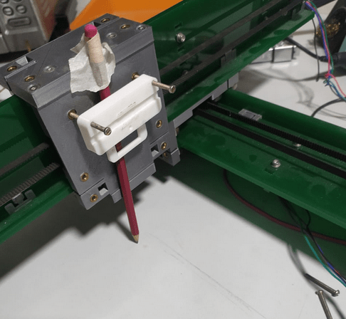
Now I need a g code executer ,I've done cnc plotter project before so I have g code executer software in my PC Also have some examples g code on my pc
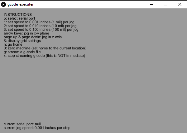
This executer is built on an open source platform called Processing .I place a pice of paper under the cnc and homed manually to a corner were x is 0 and y is 0. Then plugged to computer and connected to the executer Software and turned ON the main power.It starts draw the gcode file have some problems with end effector.but its ok for testing
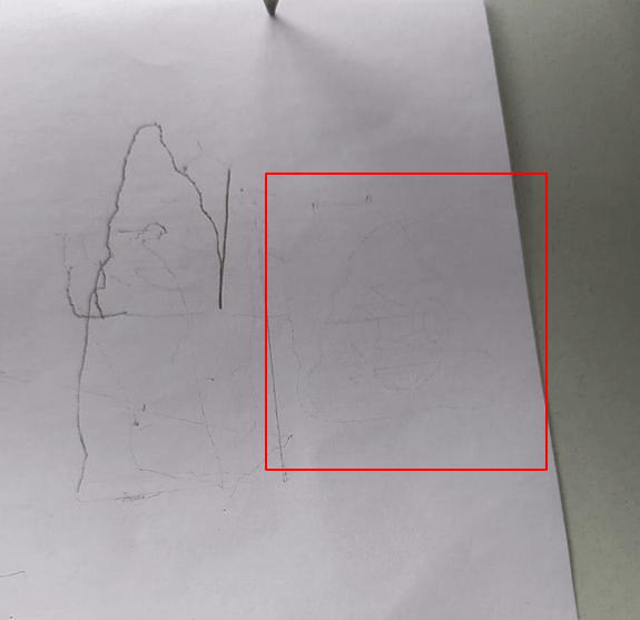
After a long trials got something meaningful on the paper. I was given Gcode file of a Poop emoji draws well so the Firmware was a success!.now we have to create the firmware to the core x-y machine that we are making
Core XY Kinematics
The core XY mechanism is different from other type of mechanism like cartesian both motors required to control each individual axis if we only rotate one motor the head will go + or - diagonally
If we rotate the motor at same direction it moves alongside x axis ,but if the motors in opposite direction the head will move alongside y axis.We found more about the Core XY from the corexy.com website
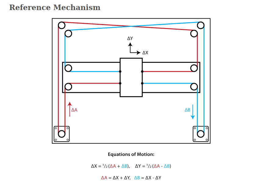
According to the corexy-theory We have an equation for the Motor steps from X Y coordinates given by G CODE . You can see the maths from the above picture.To modify the firmware Abel Tomy helps me with the math which was very simpler than I thought
          Motor A Steps = X+Y // from ΔA=Δx+ΔY
          Motor B Steps = X-Y // from ΔB=ΔX-ΔY
According to the match I modified the Firmware for the core xy mechanism
Edited Firmware CODE :-
#include < Servo.h>
//#include < Stepper.h>
#include < AccelStepper.h>
#include < MultiStepper.h>
AccelStepper stepper1(AccelStepper::DRIVER, A0,A1);
AccelStepper stepper2(AccelStepper::DRIVER, A6,A7);
MultiStepper steppers;
#define LINE_BUFFER_LENGTH 512
const int penZUp = 40;
const int penZDown = 80;
const int penServoPin = 6;
const int stepsPerRevolution = 60;
Servo penServo;
//
//Stepper myStepperY(stepsPerRevolution, 5,3,4,2);
//Stepper myStepperX(stepsPerRevolution, 11,9,10,8);
struct point {
float x;
float y;
float z;
};
struct point actuatorPos;
float StepInc = 1;
int StepDelay = 0;
int LineDelay = 50;
int penDelay = 50;
float StepsPerMillimeterX = 160.0;
float StepsPerMillimeterY = 160.0;
float Xmin = 0;
float Xmax = 100;
float Ymin = 0;
float Ymax = 100;
float Zmin = 0;
float Zmax = 1;
float Xpos = Xmin;
float Ypos = Ymin;
float Zpos = Zmax;
boolean verbose = true;
long positions[2]; // Array of desired stepper positions
void setup() {
Serial.begin( 9600 );
pinMode(A2,OUTPUT);
pinMode(38,OUTPUT);
// Configure each stepper
stepper1.setMaxSpeed(4000);
stepper1.setAcceleration(5000);
stepper1.setCurrentPosition(0);
stepper2.setMaxSpeed(4000);
stepper2.setAcceleration(5000);
stepper2.setCurrentPosition(0);
steppers.addStepper(stepper1);
steppers.addStepper(stepper2);
digitalWrite(38,LOW);
digitalWrite(A2,LOW);
penServo.attach(penServoPin);
penServo.write(penZUp);
delay(200);
// myStepperX.setSpeed(200);
// myStepperY.setSpeed(200);
Serial.println("Mini CNC Plotter alive and kicking!");
Serial.print("X range is from ");
Serial.print(Xmin);
Serial.print(" to ");
Serial.print(Xmax);
Serial.println(" mm.");
Serial.print("Y range is from ");
Serial.print(Ymin);
Serial.print(" to ");
Serial.print(Ymax);
Serial.println(" mm.");
}
void loop()
{
delay(200);
char line[ LINE_BUFFER_LENGTH ];
char c;
int lineIndex;
bool lineIsComment, lineSemiColon;
lineIndex = 0;
lineSemiColon = false;
lineIsComment = false;
while (1) {
while ( Serial.available()>0 ) {
c = Serial.read();
if (( c == '\n') || (c == '\r') ) {
if ( lineIndex > 0 ) {
line[ lineIndex ] = '\0';
if (verbose) {
Serial.print( "Received : ");
Serial.println( line );
}
processIncomingLine( line, lineIndex );
lineIndex = 0;
}
else {
}
lineIsComment = false;
lineSemiColon = false;
Serial.println("ok");
}
else {
if ( (lineIsComment) || (lineSemiColon) ) { // Throw away all comment characters
if ( c == ')' ) lineIsComment = false; // End of comment. Resume line.
}
else {
if ( c <= ' ' ) { // Throw away whitepace and control characters
}
else if ( c == '/' ) { // Block delete not supported. Ignore character.
}
else if ( c == '(' ) { // Enable comments flag and ignore all characters until ')' or EOL.
lineIsComment = true;
}
else if ( c == ';' ) {
lineSemiColon = true;
}
else if ( lineIndex >= LINE_BUFFER_LENGTH-1 ) {
Serial.println( "ERROR - lineBuffer overflow" );
lineIsComment = false;
lineSemiColon = false;
}
else if ( c >= 'a' && c <= 'z' ) { // Upcase lowercase
line[ lineIndex++ ] = c-'a'+'A';
}
else {
line[ lineIndex++ ] = c;
}
}
}
}
}
}
void processIncomingLine( char* line, int charNB ) {
int currentIndex = 0;
char buffer[ 64 ]; // Hope that 64 is enough for 1 parameter
struct point newPos;
newPos.x = 0.0;
newPos.y = 0.0;
// Needs to interpret
// G1 for moving
// G4 P300 (wait 150ms)
// G1 X60 Y30
// G1 X30 Y50
// M300 S30 (pen down)
// M300 S50 (pen up)
// Discard anything with a (
// Discard any other command!
while( currentIndex < charNB ) {
switch ( line[ currentIndex++ ] ) { // Select command, if any
case 'U':
penUp();
break;
case 'D':
penDown();
break;
case 'G':
buffer[0] = line[ currentIndex++ ]; // /!\ Dirty - Only works with 2 digit commands
// buffer[1] = line[ currentIndex++ ];
// buffer[2] = '\0';
buffer[1] = '\0';
switch ( atoi( buffer ) ){ // Select G command
case 0: // G00 & G01 - Movement or fast movement. Same here
case 1:
// /!\ Dirty - Suppose that X is before Y
char* indexX = strchr( line+currentIndex, 'X' ); // Get X/Y position in the string (if any)
char* indexY = strchr( line+currentIndex, 'Y' );
if ( indexY <= 0 ) {
newPos.x = atof( indexX + 1);
newPos.y = actuatorPos.y;
}
else if ( indexX <= 0 ) {
newPos.y = atof( indexY + 1);
newPos.x = actuatorPos.x;
}
else {
newPos.y = atof( indexY + 1);
indexY = '\0';
newPos.x = atof( indexX + 1);
}
drawLine(newPos.x, newPos.y );
// Serial.println("ok");
actuatorPos.x = newPos.x;
actuatorPos.y = newPos.y;
break;
}
break;
case 'M':
buffer[0] = line[ currentIndex++ ]; // /!\ Dirty - Only works with 3 digit commands
buffer[1] = line[ currentIndex++ ];
buffer[2] = line[ currentIndex++ ];
buffer[3] = '\0';
switch ( atoi( buffer ) ){
case 300:
{
char* indexS = strchr( line+currentIndex, 'S' );
float Spos = atof( indexS + 1);
// Serial.println("ok");
if (Spos == 30) {
penDown();
}
if (Spos == 50) {
penUp();
}
break;
}
case 114: // M114 - Repport position
Serial.print( "Absolute position : X = " );
Serial.print( actuatorPos.x );
Serial.print( " - Y = " );
Serial.println( actuatorPos.y );
break;
default:
Serial.print( "Command not recognized : M");
Serial.println( buffer );
}
}
}
}
void drawLine(float x1, float y1) {
if (verbose)
{
Serial.print("fx1, fy1: ");
Serial.print(x1);
Serial.print(",");
Serial.print(y1);
Serial.println("");
}
if (x1 >= Xmax) {
x1 = Xmax;
}
if (x1 <= Xmin) {
x1 = Xmin;
}
if (y1 >= Ymax) {
y1 = Ymax;
}
if (y1 <= Ymin) {
y1 = Ymin;
}
if (verbose)
{
Serial.print("Xpos, Ypos: ");
Serial.print(Xpos);
Serial.print(",");
Serial.print(Ypos);
Serial.println("");
}
if (verbose)
{
Serial.print("x1, y1: ");
Serial.print(x1);
Serial.print(",");
Serial.print(y1);
Serial.println("");
}
// Convert coordinates to steps
x1 = (int)(x1*StepsPerMillimeterX);
y1 = (int)(y1*StepsPerMillimeterY);
mov(x1,y1);// sending the co-ordinates
float x0 = Xpos;
float y0 = Ypos;
// Let's find out the change for the coordinates
long dx = abs(x1-x0);
long dy = abs(y1-y0);
int sx = x0< x1 ? StepInc : -StepInc;
int sy = y0< y1 ? StepInc : -StepInc;
long i;
long over = 0;
if (dx > dy) {
for (i=0; i< dx; ++i) {
// Serial.print("x:");
// Serial.println(sx);
// myStepperX.step(sx);
over+=dy;
if (over>=dx) {
over-=dx;
// Serial.print("y:");
// Serial.println(sy);
// myStepperY.step(sy);
}
delay(StepDelay);
}
}
else {
for (i=0; i< dy; ++i) {
// Serial.print("y:");
// Serial.println(sy);
// myStepperY.step(sy);
over+=dx;
if (over>=dy) {
over-=dy;
// Serial.print("x:");
// Serial.println(sx);
// myStepperX.step(sx);
}
delay(StepDelay);
}
}
if (verbose)
{
Serial.print("dx, dy:");
Serial.print(dx);
Serial.print(",");
Serial.print(dy);
Serial.println("");
}
if (verbose)
{
Serial.print("Going to (");
Serial.print(x0);
Serial.print(",");
Serial.print(y0);
Serial.println(")");
}
delay(LineDelay);
Xpos = x1;
Ypos = y1;
}
void penUp() {
penServo.write(penZUp);
delay(LineDelay);
Zpos=Zmax;
if (verbose) {
Serial.println("Pen up!");
}
}
void penDown() {
penServo.write(penZDown);
delay(LineDelay);
Zpos=Zmin;
if (verbose) {
Serial.println("Pen down.");
}
}
void mov(long x,long y){
positions[0] = x+y;// from ΔA=Δx+ΔY
positions[1] = x-y;// from ΔB=ΔX-ΔY
steppers.moveTo(positions);
steppers.runSpeedToPosition(); // Blocks until all are in position
// stepper2.setCurrentPosition(0);
// stepper1.setCurrentPosition(0);
}
The mechanical team almost finishing the machine design and not done completely.so we can't test the firmware that we made for it
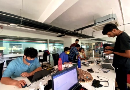
I joined them to help to see what I can do. Here is the picture that shows everyone busy this week (Taken by Alfia)
End Effector
The end effector mechanism was designed by Abhinav Ajith. It has 2 pen holders controlled by one single servo motor positioning each angle for controlling each Pen up and Down motion.
I was helping him to Prototype the End effector Then we assembled together .Check Abhinav's Machine Design week Documentation for more details. Then we tested It's operation by running a servo Example code using the Arduino platform.
CNC Shield
All of my group was busy in the week for completing the Mechanical design so its all in progress as an electronics guy in the Team What I could have done is to do the electronics parallel .We already finished the minimum electronics hardware setup to run the machine any way so I've got time to build a CNC PCB for our Machine.
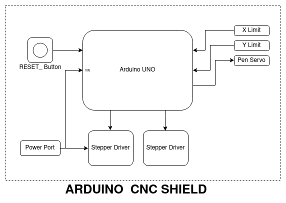
I built this block diagram to get a better understanding about what we are gonna make. We are decided to build a CNC Shield on the top of the arduino UNO to interface those two stepper motor drivers and the servo. Building entire CNC PCB is little difficult and we don't have time for that.
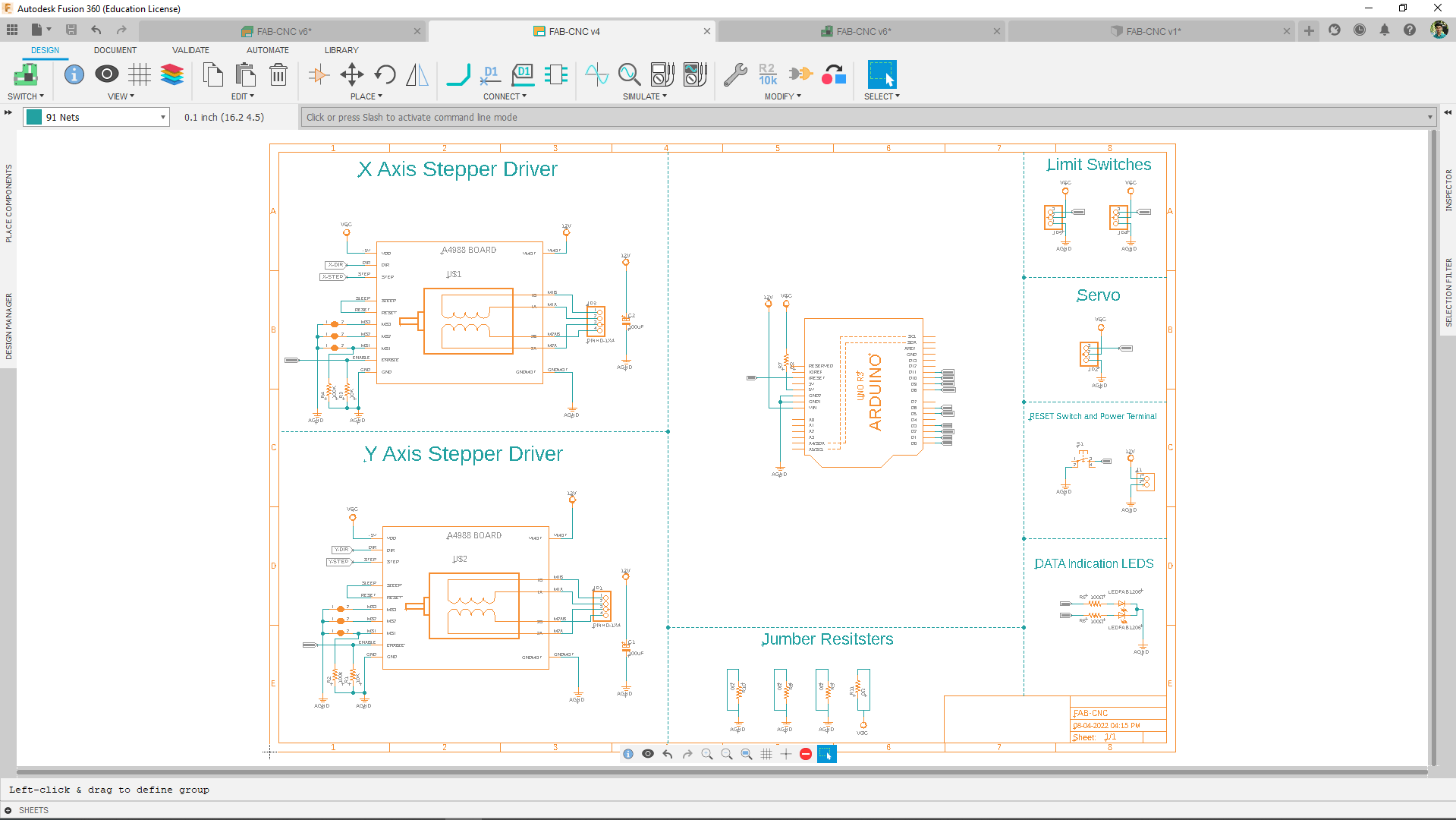
So I build the schematic and the board in fusion 360 . the reffrence of the Motor driver circuit was taken from the Ramp 1.4 3D Printer shield schematic diagram.
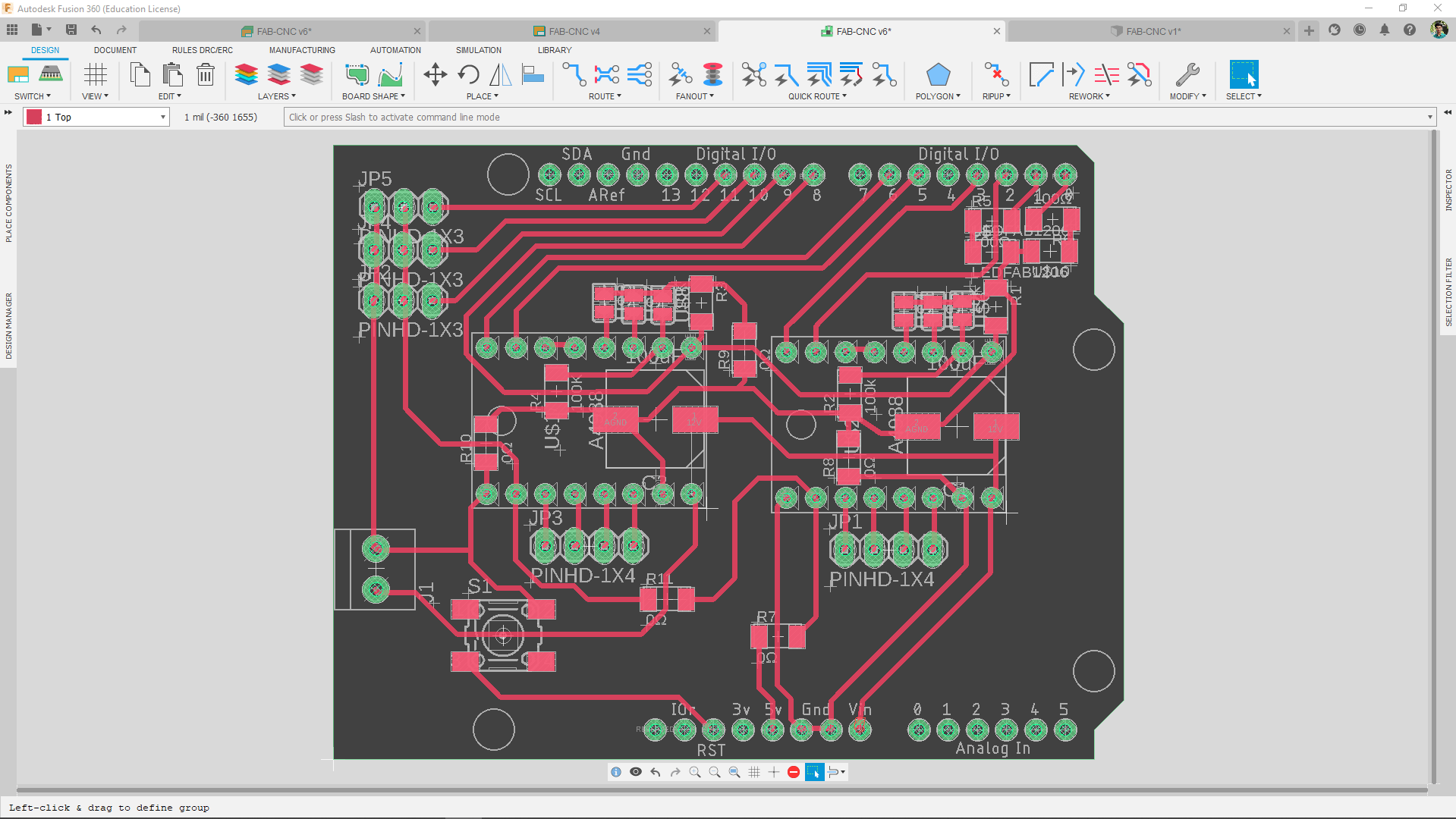
Here is the final design of the board looks like . I do have small problem to make it happen, It's one sided so the motor driver will be sitting on a adapter which should be soldered from the bottom side of the board. I've decided to use the revetting techniques to solve the problem.
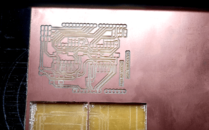
I milled the board out using the Modella Milling machine from our lab and also did the through holes for the rivets after some adjustments in the design.
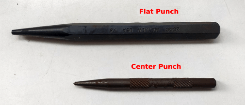
These are the Punches used for rivetting in our lab. The small one is a kind of pointy center punch that helps to make a flanch forming curve on the rivet. And the big one is a flat type punch helps to finish the flanch that formed using the pointy center punch.
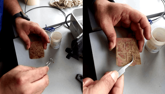
we use the tweezer to put the rivets in place then used the punches to complete the riveting process. My group mate pallab shresthahelps me to rivet the board .
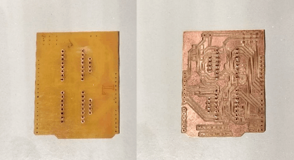
Here is the puture of the board after we finishing the revetiing process. yea right that's a lot of rivets hope it's works
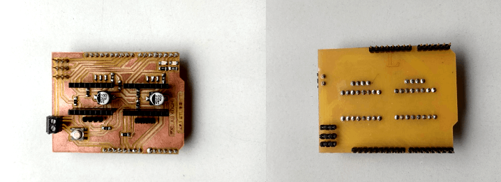
Then I grabed the componnets from inventory room and soldered everything in place. You can see the male and female heder pins are not SMD and the picture also shows why the revets are used in this design.
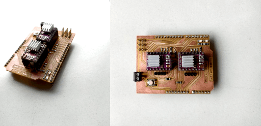
So,The CNC sheild is all set to test as next step we have to complete the Mechanical assemply of our core xy machine.
Mechanical Assembly
We almosted finished the Electronics hardware and firmware, And the mechanical team completed the design and testing now its time for the production and assembly.
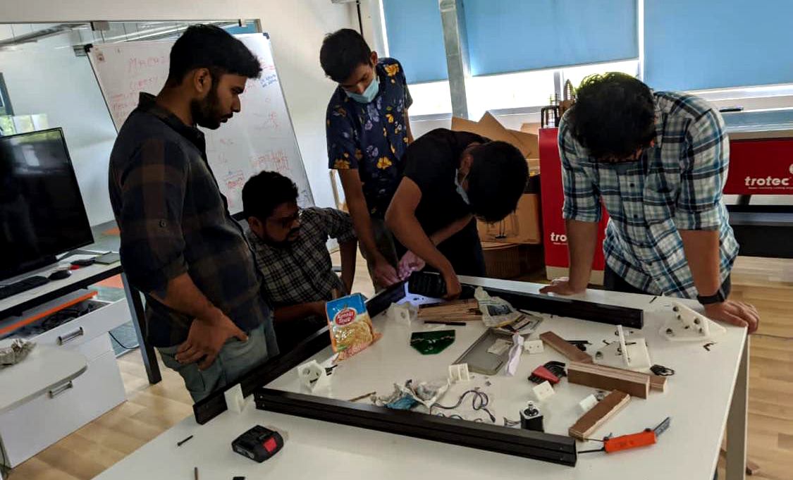
During the assembly we faced some issues of missiglignment becouse we dont have any drill press to drill streight and perpendicular hole . but with some skills and instructors help we re assembled the missalgned fram in to a proper alignment.
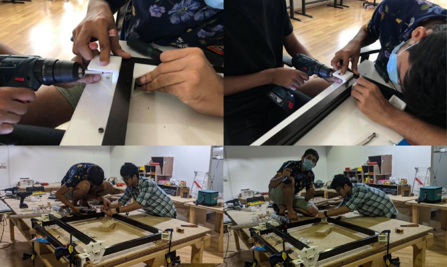
We also works at night at the lab to finish the mechanical assembly. It was totally new and awesome experiance working in a team.
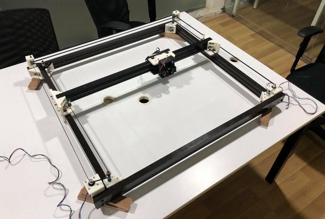
Here is the picture of the machine after the mechanical asssembly all done. Also attached two motors and the end effector servo in it. For more about mechanical Design , testing and assembly see Pallab's and Abel's Mchine week documentation
We check the actuations by moving with our hand with out any electronics attached. we can feel ther movement during this test also its better to understand if any truble in the movement.
corexy - Testing
So far the week is almost over and everyboady wants to go back to home becouse of the break happening during machine weeks. Tht's why we decided to go a test ploting without proper electronics assembly.
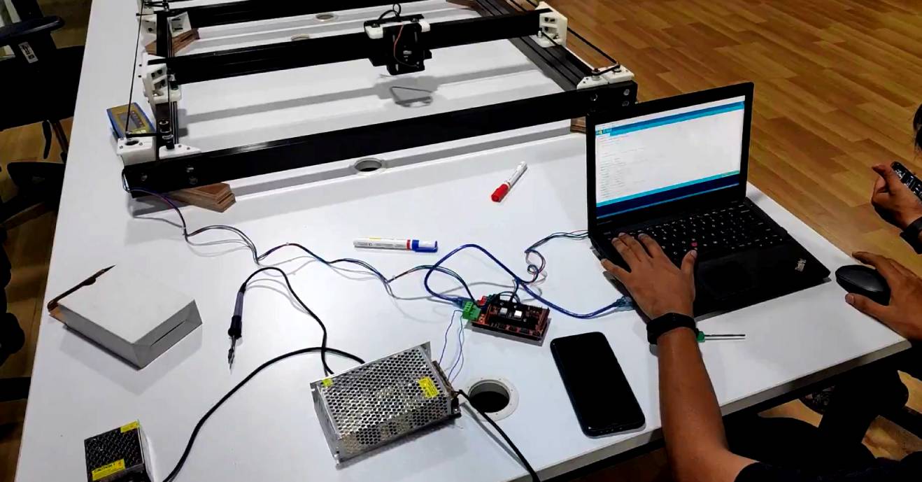
we set-up a simple electronics hardware just to power those motor this way we can test the CoreXY mechanism.we didnt use the sheild we build during the session instead we chose the ramp sheild in-order to avoid any Electrical error if there is any.
After some effort of few hours we managed to draw a Square as our machine's first baby step. the code used for drawing the square isnt a Gcode based firmware.Instead we created a coustome code to draw the square and testing the coreXY equation. we did not connect the pen up and dow servo at this time.
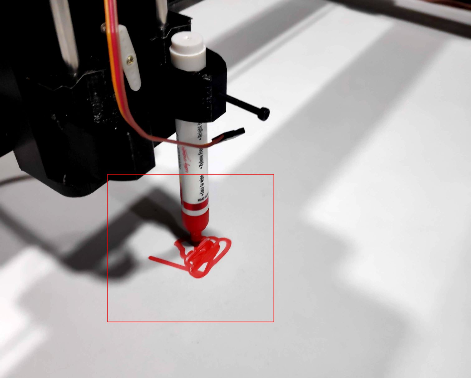
Then we implemented the coreXY firm ware that we made before and drew the poop emoji. see the above picture. It was so small to our machine and it's messy becouse of there is no pen up and down motion.
here is the video of our machine and us trying to draw a lamborgini image on the table . Turns out it was a half success.
Machine week Review
I wasn't at the lab while we are having the wmachine week review .So Pallab and Abel joined from the LAB to show and expline our eforts.
Here is the video snipet of our machine week review we named our machine P- NASH .Unmute for the sound . For the orginal see this vimeo link
References
- Fab Academy Mechanical Design classes
- Fab Academy Machine Design classes
- www.airspayce.com | AccelStepper.h library
- processing.org | For Making Desktop Applications
- Jake read's Fab documentation
- Corexy Doccumentation
Downloads
- FAB CNC Sheild PCB Design Files
- FAB CNC Code