Networking and Communications
week 13 assignment is to design, build, and connect wired or wireless node(s) with network or bus addresses
We are still working from home because of the pandemic situation and can't access the lab its kind of fully closed for a long time.So I decided to do an I2C master-slave Bus to control an RGB LED on it
I2C Protocol
IIC or I2C is short form of Inter-Integrated Circuits,It's a type protocol to communicate in between Integrated circuits,Microcontrollers,sensors etc.. just like USB in Computers.there are many communication peripheral available for Microcontrollers.Most of the Microcontrollers have two or more different type of protocols. The advantages of I2C is most of the Devices supports the protocol and very easy to use two wire required for data and clock.
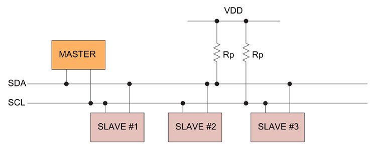
The above figure shows how a simple I2C Network look like.One device act as Master others are called slaves,and bidirectional data transfer are possible with the permission of the master device.The pins that required for this communication protocol are the SDA (Serial Data) and THe SCL (Serial Clock)
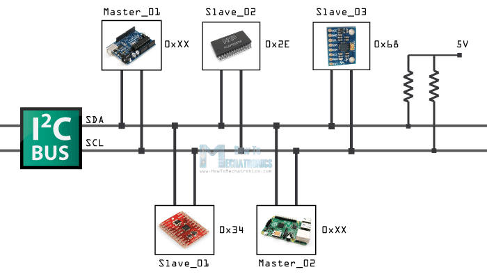
Each devices in the I2C bus has it's own addresses,it possible to connect almost upto upto 128(112) devices when using 7 bits addressing and almost upto 1024(1008)devices when using the 8 bits addressing
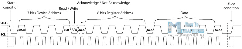
the above figure shows how the clock and data signals are being used in the I2C buss communication.I referred this doc from Howtomechatronics.com
I already did a I2C display project during the Output week check out my Output Devices week to know more..
Sketching The Circuit
For this week assignment I decided to build an Attiny412 coin(round shaped PCB) with an RGB LED and the colors of the led can be change using my echo board AKA the badge which I built during my Electronics Design week that runs on a Attiny84 chip
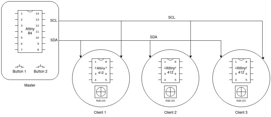
I made a simple diagram using Draw.io which shows in above figure,this explains my plan for this week.and also one design is enough to create multiple PCB.Using those buttons on the badge PCB I will able to select each individual RGB coin and also able to change the colour individually
Designing the PCB with Fusion 360
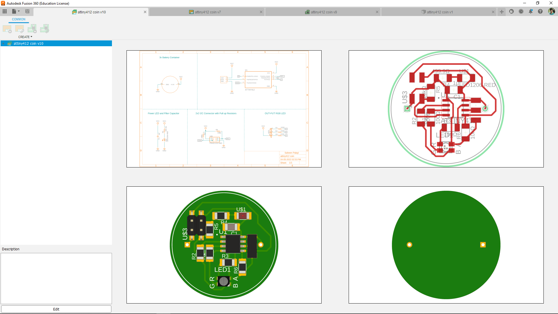
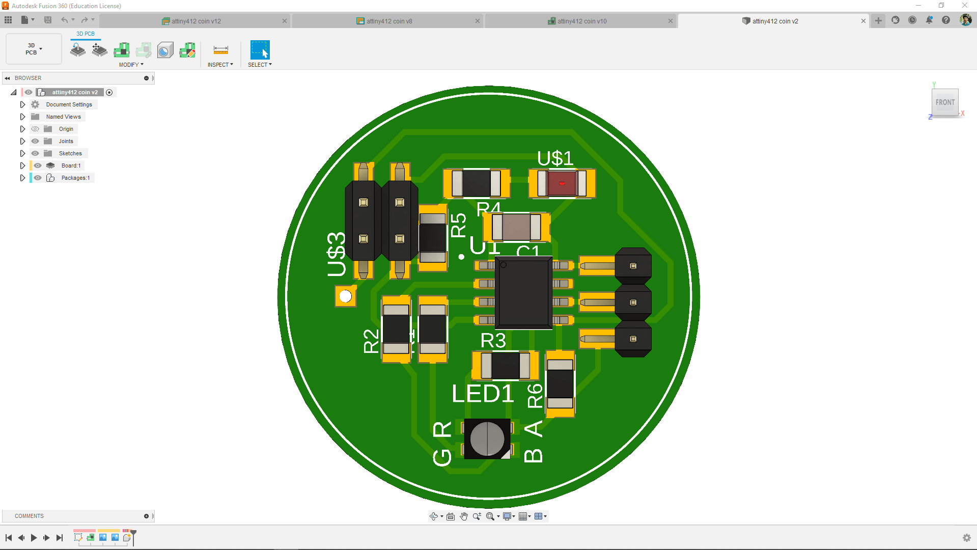
I created an Electronics project in fusion 360 and completed the PCB design please refer my Electronics Design week to know how I design PCBs in Fusion 360
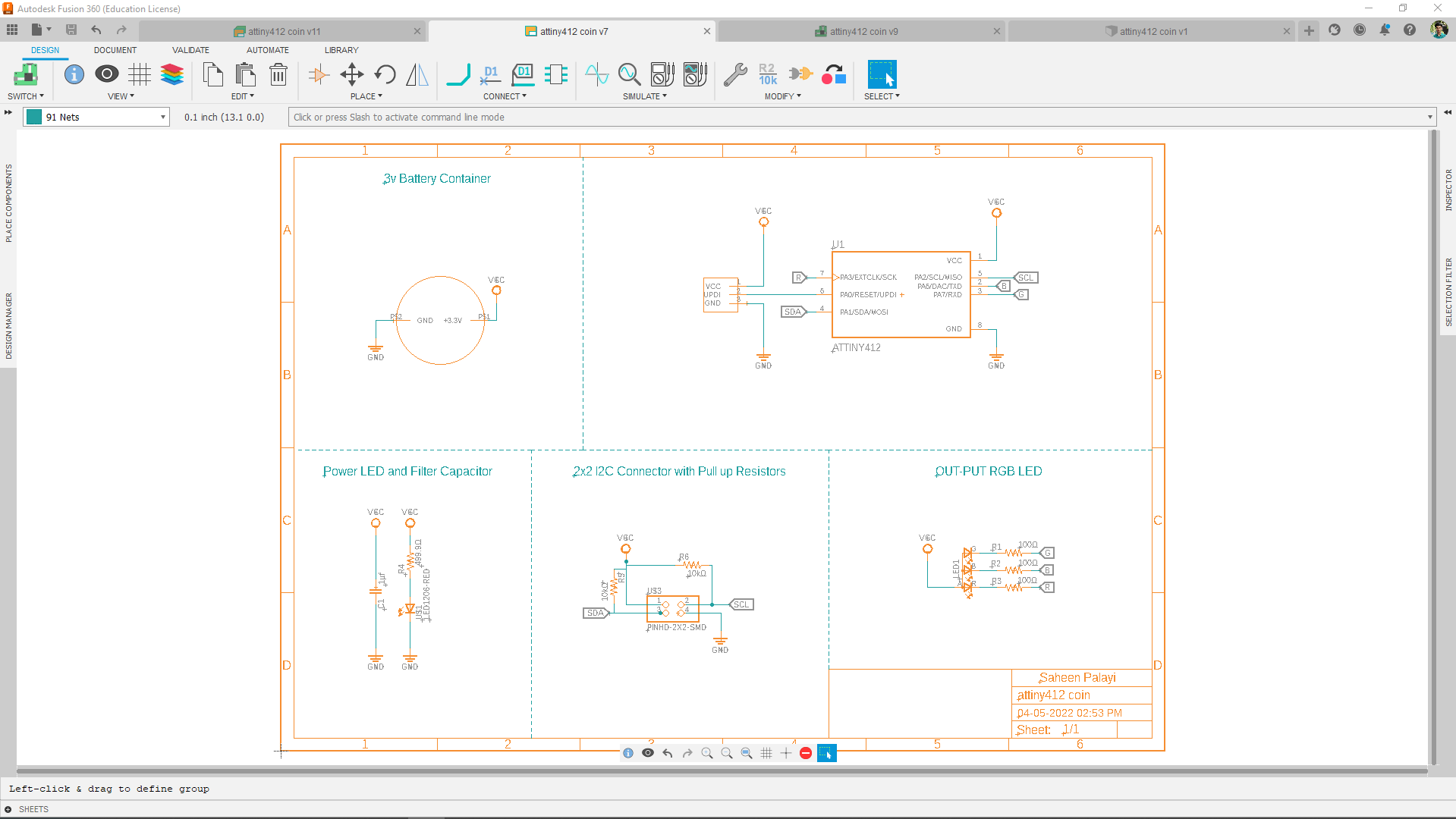
Using the Attiny412 is pretty simple doesn't need much component for minimum circuit.Also added a 10 K Pull up resister for the SCL and SDA pins of the Attiny412. After creating the schematic I exported to PCB
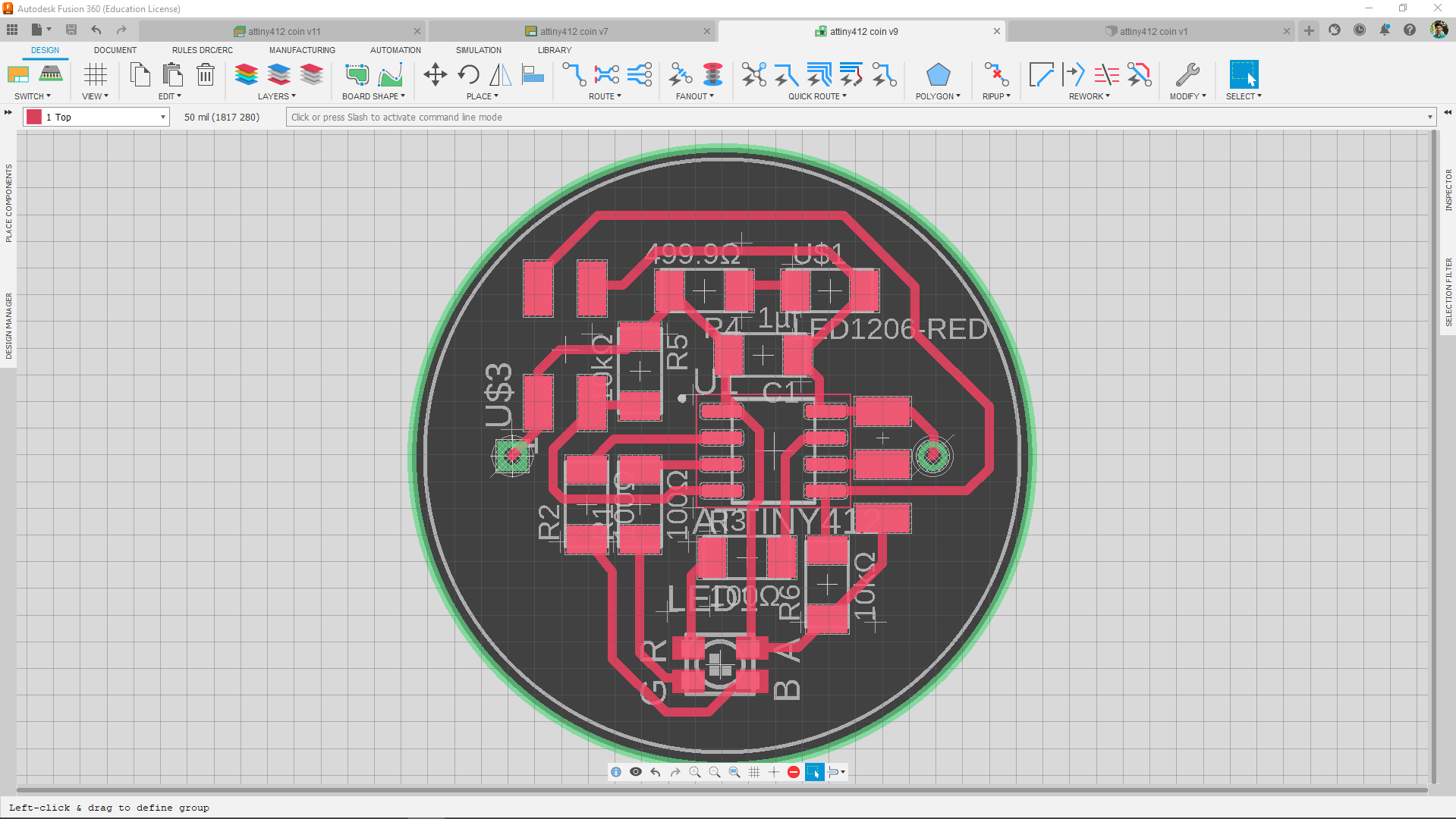
Then I routed all the traces.and of course this isn't a one click process but for this PCB it was simple so refer my Electronics Design week to know how I creating PCBs in Fusion 360
Milling and soldering
The Milling and fabrication was actually done when we got back to the lab after the lockdown time period of two month. so the classes of FAB Academy 2021 was almost ended and everybody around the world started their project presentation.So I continued this week assignment after My final project presentation.
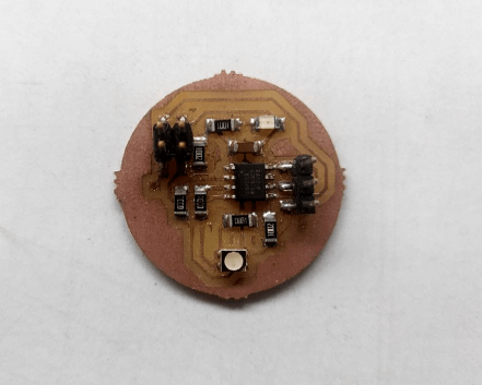
Here is the my t412 coin board after soldering.The milling and fabrication of the each tiny412 coin where done during the Wildcard week for the Pick and Place machining process(which is Basically a upcoming week according to the assignment).
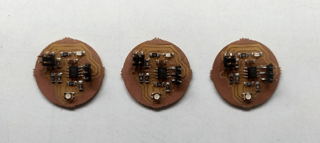
Using panelizing design technique I made 3 of them and assembled every components except the connector using the pick n place machine from our lab. To know more about how I done and soldered the boards , see my amazing documentation of Wildcard Week.
Programing
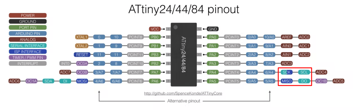
Like I planned before, I'm gonna use my electronics Design week Board as Master device . I found out the MISO and SCK pins are also sharing the SDA and SCL ,So i can use them to network through the t412 coins I made.
So,For the Networking I have to make a communication wire to connect all of my boards together.I will be using the wire header connectors and flat cables to create the wire.
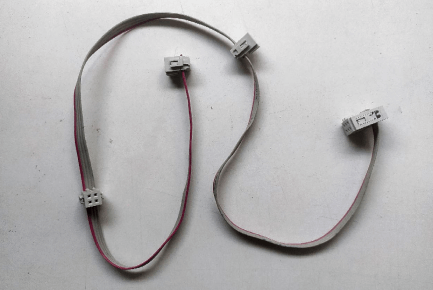
I built the wire using 4 pair flat cable and 2x2 (3 pcs), 2x3 (1 pcs) connectors , The master board has 6 pin out which I don't need all so I've checked the pins I want then placed in the 2x3 connectors gap then pressed using a mallet.
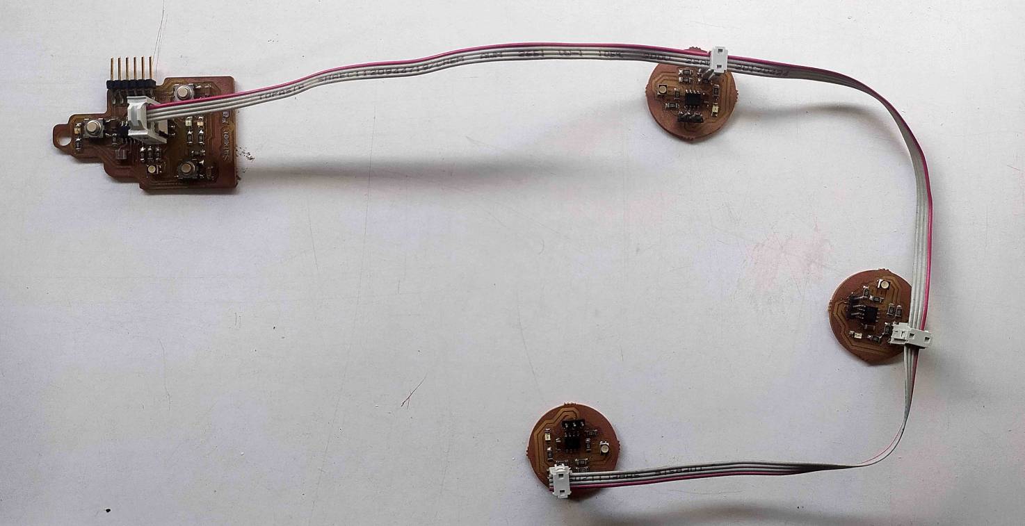
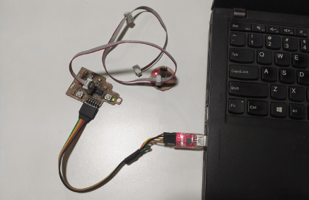
Here is my final hardware setup and It's all set to program. The power will be connects through the 6 PIN FTDI Connector and the programing is bit tricky I've to program the Master board first then will connect to the network to perform tasks.
With Arduino IDE
For the I2C networking There are a beautiful library called wire.h available in arduino which can perform the tasks I planned to do.So from the given examples I opened the master example code and try to compile for the Attiny84.
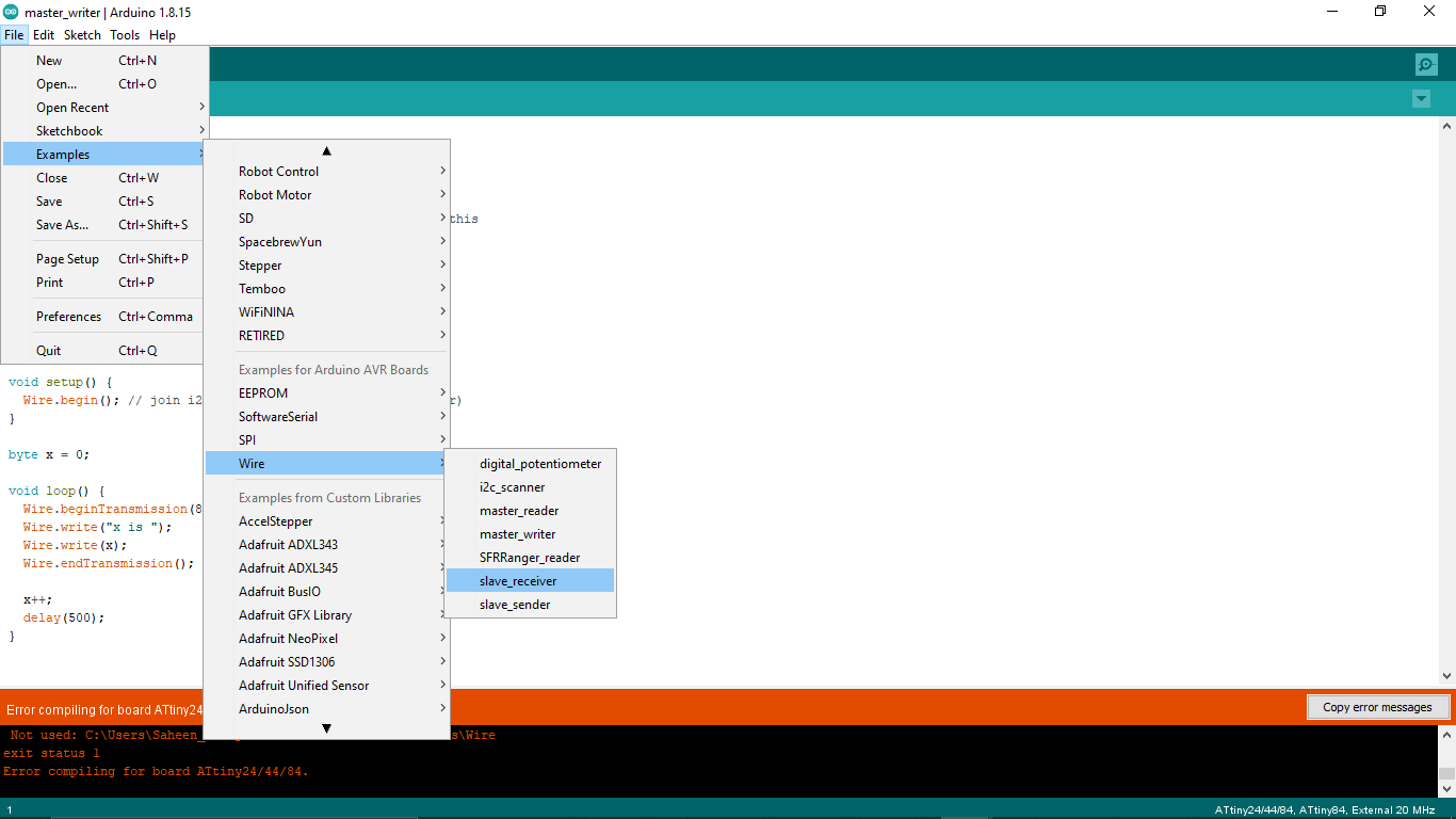
But I got error during the compilation so I found out the board manager I'm using not supports the wire.h library . I was following one of previous student's documentation Mr. Salamn Faris's Network and Communication week assignment.So he mentioned the issue with the board manager and recommended to use a ATTinyCore Board manager by SpenceKonde.
http://drazzy.com/package_drazzy.com_index.jsonI added the above installation link in the arduino IDE's preference tab which I got from the SpenceKonde's ATTinyCore github repository. Then I installed the board manger like I did in my Electronics Design week.
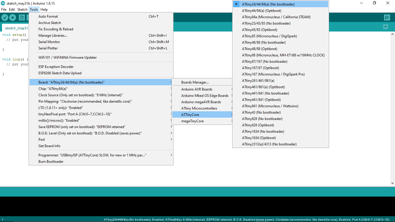
The ATTinyCore has more options than the one which I used before and supports a lot of arduino libraries.So I loaded the wire.h Programs and started to test out them.
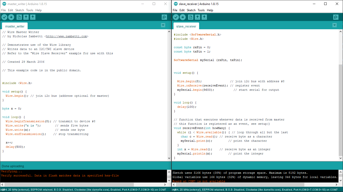
So I've tested the I2C communication between my boards using the Master slave example programs from wire.h library. The program was actually made by a guy named Nicholas Zambetti and the library works for almost all the arduino support Microcontrollers.
Wire.h Master Writer CODE :-
                        // Wire Master Writer
                        // by Nicholas Zambetti < http://www.zambetti.com>

                        // Demonstrates use of the Wire library
                        // Writes data to an I2C/TWI slave device
                        // Refer to the "Wire Slave Receiver" example for use with this

                        // Created 29 March 2006

                        // This example code is in the public domain.


                        #include < Wire.h>

                        void setup() {
                          Wire.begin(); // join i2c bus (address optional for master)
                        }

                        byte x = 0;

                        void loop() {
                          Wire.beginTransmission(8); // transmit to device #8
                          Wire.write("x is ");        // sends five bytes
                          Wire.write(x);              // sends one byte
                          Wire.endTransmission();    // stop transmitting

                          x++;
                          delay(500);
                        }
The above code where programed to one of the Attiny412 I2C Coin board Because we cant connect any serial output from the coin board so the coin board will send the master messages and send the data to the slave board with the address of the 8 .
Wire.h Slave Receiver CODE :-
                        //
                        // Slave-reader
                        //
                        // Wire Slave Receiver
                        //
                        // by Nicholas Zambetti < http://www.zambetti.com> and modified by Saheen Palayi 06/06/2022
                        //
                        // This work may be reproduced, modified, distributed,
                        // performed, and displayed for any purpose, but must
                        // acknowledge this project. Copyright is retained and
                        // must be preserved. The work is provided as is; no
                        // warranty is provided, and users accept all liability.
                        //


                        // Demonstrates use of the Wire library
                        // Receives data as an I2C/TWI slave device
                        // Refer to the "Wire Master Writer" example for use with this

                        // Created 29 March 2006 by Nicholas Zambetti

                        // This example code is in the public domain.


                        //Added software serial for Attiny84
                        #include < SoftwareSerial.h>
                        #include < Wire.h>


                        // Software serial rx,tx pins of Attiny84
                        const byte rxPin = 0;
                        const byte txPin = 1;


                        //declaring mySerial as SoftwareSerial
                        SoftwareSerial mySerial (rxPin, txPin);


                        void setup() {

                          Wire.begin(8);                // join i2c bus with address #8
                          Wire.onReceive(receiveEvent); // register event
                          mySerial.begin(9600);           // start serial for output
                        }

                        void loop() {
                          delay(100);
                        }

                        // function that executes whenever data is received from master
                        // this function is registered as an event, see setup()
                        void receiveEvent(int howMany) {
                          while (1 < Wire.available()) { // loop through all but the last
                            char c = Wire.read(); // receive byte as a character
                            mySerial.print(c);         // print the character
                          }
                          int x = Wire.read();    // receive byte as an integer
                          mySerial.println(x);         // print the integer
                        }
Here is the modified Slave receiver program from Wire.h library which uploaded to My design week Attiny84 based badge board. It has an FTDI connector to read the out put through Serial USART . so I've added the Software serial library in the program because the Attiny84 doesn't have any hardware serial.
Here is my test set-up so all I need to turn on the serial monitor for the FTDI. but during the test I didn't get the result first because there is an issue in the Attiny84 based badge board of mine.
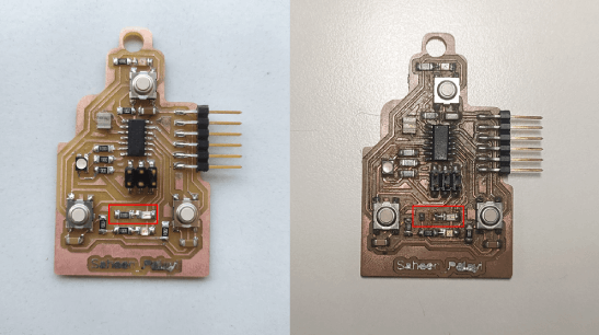
One of the I2C line (SCL) was connected to an LED so whenever the I2C start working the power will draw through the LED so the Clock pin never get always high like in the I2C communication protocol required. So I removed the Resister of the LED to break the connection That fixed my problem.
Here is the Output result of the Master -slave Wire.h Library test The Attiny412 coin sending the two type of data one is a string "X is " and another one is an integer data which increment and send again to the slave every 0.5 second.
So my plane is very clear here I can send data vise versa also this was just a test for checking the wire.h library works or not in these hardwares I'm using.
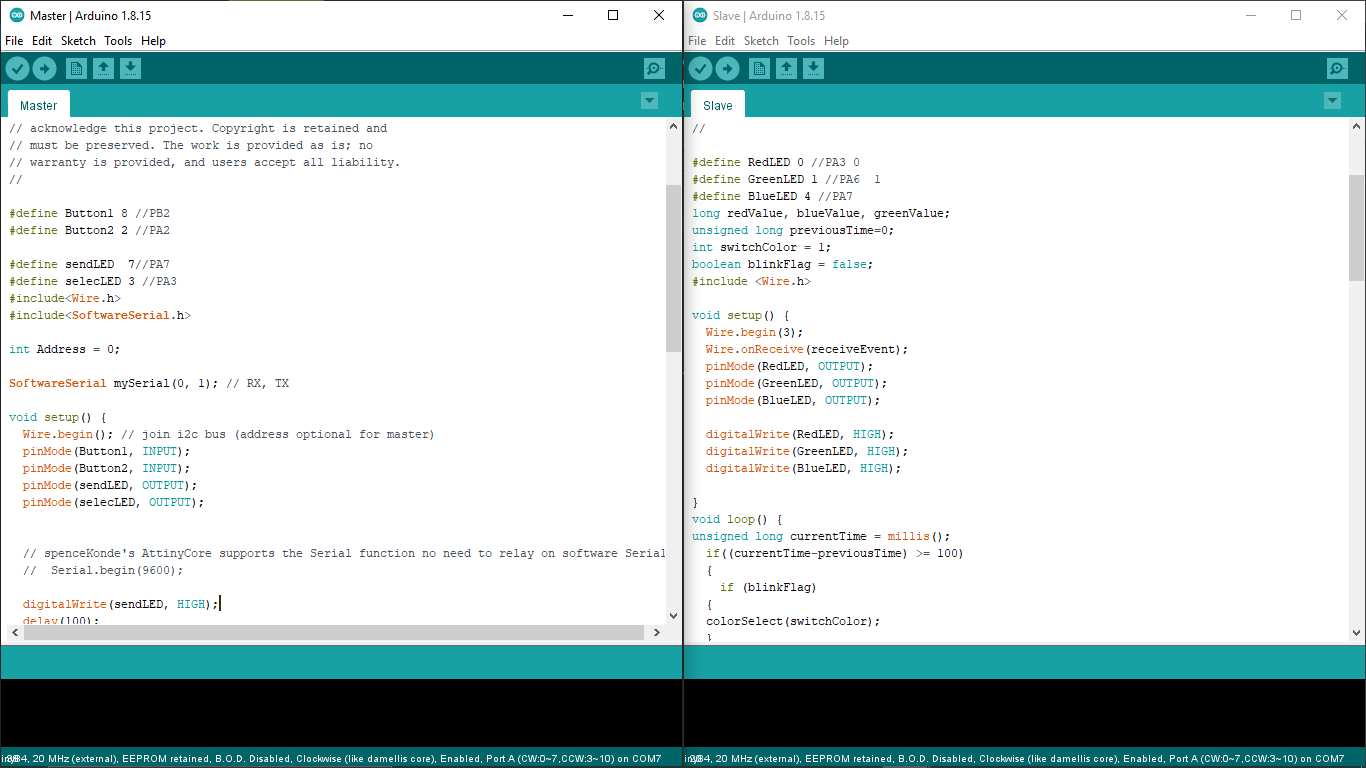
Then I've created a master and slave programs in Arduino IDE by modifying the Wire.h Master write,Slave Receiver programs.This time the master will be the Attiny84 based badge board and the tiny412 coin boards will be the clients or slaves of the master.
Attiny84 badge Master CODE :-
                        //
                        // Master.ino
                        //
                        // I2C Master
                        //
                        // Saheen Palayi 06/06/2022
                        //
                        // This work may be reproduced, modified, distributed,
                        // performed, and displayed for any purpose, but must
                        // acknowledge this project. Copyright is retained and
                        // must be preserved. The work is provided as is; no
                        // warranty is provided, and users accept all liability.
                        //

                        #define Button1 8 //PB2
                        #define Button2 2 //PA2

                        #define sendLED  7//PA7
                        #define selecLED 3 //PA3
                        #include
                        #include

                        int Address = 0;

                        SoftwareSerial mySerial(0, 1); // RX, TX

                        void setup() {
                          Wire.begin(); // join i2c bus (address optional for master)
                          pinMode(Button1, INPUT);
                          pinMode(Button2, INPUT);
                          pinMode(sendLED, OUTPUT);
                          pinMode(selecLED, OUTPUT);


                          // spenceKonde's AttinyCore supports the Serial function no need to relay on software Serial
                          //  Serial.begin(9600);

                          digitalWrite(sendLED, HIGH);
                          delay(100);
                          digitalWrite(sendLED, LOW);
                          delay(100);
                          digitalWrite(sendLED, HIGH);
                        }

                        void loop() {

                          //Address selection
                          if (digitalRead(Button1) == HIGH)
                          {
                            if (Address != 0) {
                              Wire.beginTransmission(Address);
                              Wire.write(0);        // sends five bytes
                              Wire.endTransmission();    // stop transmitting
                            }
                            Address++;
                            if (Address > 3) {
                              Address = 1;
                            }

                            Wire.beginTransmission(Address);
                            Wire.write(1);        // sends five bytes
                            Wire.endTransmission();    // stop transmitting

                            digitalWrite(selecLED, HIGH);
                            delay(100);
                            digitalWrite(selecLED, LOW);

                          }


                          if (digitalRead(Button2) == HIGH)
                          {
                            Wire.beginTransmission(Address); // transmit to device #8
                            Wire.write(2);        // sends five bytes
                            Wire.endTransmission();    // stop transmitting

                            digitalWrite(sendLED, LOW);
                            delay(100);
                            digitalWrite(sendLED, HIGH);
                          }

                          delay(1000);

                        }
The above code is for the Attiny84 badge board .I'm gonna use those two input button on the board for selecting each slave board and another button used for changing the color in the selected Slave board.
Attiny412 coin Slave CODE :-
                        //
                        // Slave.ino
                        //
                        // I2C Master
                        //
                        // Saheen Palayi 06/06/2022
                        //
                        // This work may be reproduced, modified, distributed,
                        // performed, and displayed for any purpose, but must
                        // acknowledge this project. Copyright is retained and
                        // must be preserved. The work is provided as is; no
                        // warranty is provided, and users accept all liability.
                        //

                        #define RedLED 0 //PA3 0
                        #define GreenLED 1 //PA6  1
                        #define BlueLED 4 //PA7
                        long redValue, blueValue, greenValue;
                        unsigned long previousTime=0;
                        int switchColor = 1;
                        boolean blinkFlag = false;
                        #include

                        void setup() {
                          Wire.begin(3);
                          Wire.onReceive(receiveEvent);
                          pinMode(RedLED, OUTPUT);
                          pinMode(GreenLED, OUTPUT);
                          pinMode(BlueLED, OUTPUT);

                          digitalWrite(RedLED, HIGH);
                          digitalWrite(GreenLED, HIGH);
                          digitalWrite(BlueLED, HIGH);

                        }
                        void loop() {
                        unsigned long currentTime = millis();
                          if((currentTime-previousTime) >= 100)
                          {
                            if (blinkFlag)
                          {
                          colorSelect(switchColor);
                          }
                          }
                           if( (currentTime-previousTime) >= 200)
                          {
                            if (blinkFlag)
                          {
                          colorSelect(0);
                          }
                          previousTime = currentTime;
                          }


                          soft_analogWrite( redValue);

                        //  delay(100);
                        }
                        void soft_analogWrite(int Value) {

                          // On period
                          for (int x = 0; x < Value; x++) {
                            digitalWrite(RedLED, LOW);
                          }

                          // Off period
                          for (int x = 0; x < (255 - Value); x++) {
                            digitalWrite(RedLED, HIGH);
                          }

                        }
                        void RGB_color(int RedLED_value, int GreenLED_value, int BlueLED_value)
                        {

                          redValue = RedLED_value;
                          //
                          analogWrite(GreenLED, (255 - GreenLED_value));
                          analogWrite(BlueLED, (255 - BlueLED_value));
                          //  Serial.print(RedLED_value);
                          //    Serial.print(GreenLED_value);
                          //      Serial.println(BlueLED_value);


                        }
                        void colorSelect(int colorOption){
                          switch (colorOption)
                          {
                            case 0:
                              RGB_color(0, 0, 0); // off
                              break;
                            case 1:
                              RGB_color(255, 0, 0); // Red
                              break;
                            case 2:
                              RGB_color(0, 255, 0); // Green

                              break;
                            case 3:
                              RGB_color(0, 0, 255); // Blue

                              break;
                            case 4:
                              RGB_color(227, 11, 92); // Raspberry
                              break;
                            case 5:
                              RGB_color(0, 255, 255); // Cyan
                              break;
                            case 6:
                              RGB_color(255, 0, 255); // Magenta
                              break;
                            case 7:
                              RGB_color(255, 255, 0); // Yellow
                              break;
                            case 8:
                              RGB_color(255, 255, 255); // White
                              break;
                          }
                        }
                        void receiveEvent(int howMany) {
                          int reciveData = Wire.read();
                          if (reciveData == 1)
                          {
                            blinkFlag = true;

                          }
                          if (reciveData == 0)
                          {
                            blinkFlag = false;
                          }
                          if (reciveData == 2)
                          {
                            switchColor ++;
                            if (switchColor >= 9)
                            {
                              switchColor = 1;
                            }
                          }
                          colorSelect(switchColor);

                        }
SO this code is for the Attiny412 coin boards so I've 3 of them so needs to change the wire address 1,2,3 for each board before programing to each board. This program was little bit tricky because one of the RGB LED pin (RED) is not supports the Hardware PWM so I had written a soft PWM and used Timer Delay for running everything parallel.once it get selected by master board the rgb will starts ON and OFF blinks with what ever color it has.If no color it starts with RED, and then we can change the color from the master Board. I only fed 8 color in the program currently.
Here is the working video of my I2C communication project awesome! Isn't ? I'll be explore more regarding the project in future really enjoyed the week.
ESP32-Walki-Talki
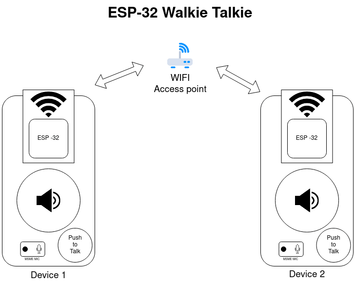
week 13 Group assignment is to send a message between two projects