- design and build a wired &/or wireless network connecting at least two processors.
- send a message between two projects.
Introduction
In this week we are going to communicate with boards , In interface week we tried bluetooth communication using HC-05 module. so here i,am going to try some base hardware level protoclos to learn more about microcontroller communication .i used some of them in arduino projects like I2C LCD interface ,we can save more and sapce. also using SPI in Our FabISP , and we daily using various USB devices . so in the world we are using somany inter-connected device and this week we are explore and build a network .Embedded electronics is all about interlinking circuits(processors or other integrated circuits) to create a symbiotic system. In order for those individual circuits to swap their information, they must share a common communication protocol. Hundreds of communication protocols have been defined to achieve this data exchange, and, in general, each can be separated into one of two categories: parallel or serial.
parallel vs serial
Parallel interfaces transfer multiple bits at the same time. They usually require buses of data - transmitting across eight, sixteen, or more wires. Data is transferred in huge, crashing waves of 1’s and 0’s.
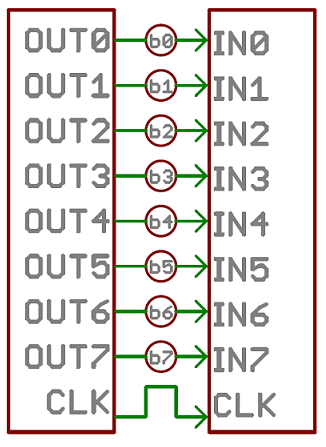
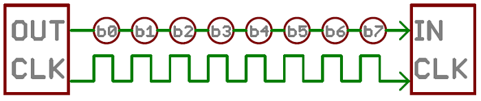
Serial interfaces stream their data, one single bit at a time. These interfaces can operate on as little as one wire, usually never more than four.
Think of the two interfaces as a stream of cars: a parallel interface would be the 8+ lane mega-highway, while a serial interface is more like a two-lane rural country road. Over a set amount of time, the mega-highway potentially gets more people to their destinations, but that rural two-laner serves its purpose and costs a fraction of the funds to build.
Asynchronous Serial
Over the years, dozens of serial protocols have been crafted to meet particular needs of embedded systems. USB (universal serial bus), and Ethernet, are a couple of the more well-known computing serial interfaces. Other very common serial interfaces include SPI, I2C, and the serial standard we’re here to talk about today. Each of these serial interfaces can be sorted into one of two groups: synchronous or asynchronous.
A synchronous serial interface always pairs its data line(s) with a clock signal, so all devices on a synchronous serial bus share a common clock. This makes for a more straightforward, often faster serial transfer, but it also requires at least one extra wire between communicating devices. Examples of synchronous interfaces include SPI, and I2C.
Asynchronous means that data is transferred without support from an external clock signal. This transmission method is perfect for minimizing the required wires and I/O pins, but it does mean we need to put some extra effort into reliably transferring and receiving data. The serial protocol we’ll be discussing in this tutorial is the most common form of asynchronous transfers. It is so common, in fact, that when most folks say “serial” they’re talking about this protocol
Rules of Serial
The asynchronous serial protocol has a number of built-in rules - mechanisms that help ensure robust and error-free data transfers. These mechanisms, which we get for eschewing the external clock signal, are:
- Data bits,
- Synchronization bits,
- Parity bits,
- Baud rate
Baud Rate
The baud rate specifies how fast data is sent over a serial line. It’s usually expressed in units of bits-per-second (bps). If you invert the baud rate, you can find out just how long it takes to transmit a single bit. This value determines how long the transmitter holds a serial line high/low or at what period the receiving device samples its line.
Baud rates can be just about any value within reason. The only requirement is that both devices operate at the same rate. One of the more common baud rates, especially for simple stuff where speed isn’t critical, is 9600 bps. Other “standard” baud are 1200, 2400, 4800, 19200, 38400, 57600, and 115200.
Wiring and Hardware
A serial bus consists of just two wires - one for sending data and another for receiving. As such, serial devices should have two serial pins: the receiver, RX, and the transmitter, TX.
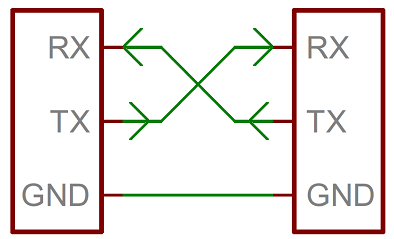
It’s important to note that those RX and TX labels are with respect to the device itself. So the RX from one device should go to the TX of the other, and vice-versa. It’s weird if you’re used to hooking up VCC to VCC, GND to GND, MOSI to MOSI, etc., but it makes sense if you think about it. The transmitter should be talking to the receiver, not to another transmitter.The same technique that we used to get data from our board to computer and read data from bluetooth module
UARTs
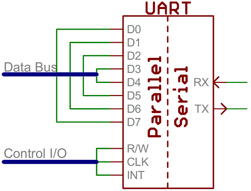
A universal asynchronous receiver/transmitter (UART) is a block of circuitry responsible for implementing serial communication. Essentially, the UART acts as an intermediary between parallel and serial interfaces. On one end of the UART is a bus of eight-or-so data lines (plus some control pins), on the other is the two serial wires - RX and TX.
UARTs do exist as stand-alone ICs, but they’re more commonly found inside microcontrollers. You’ll have to check your microcontroller’s datasheet to see if it has any UARTs. Some have none, some have one, some have many. For example, the Arduino Uno - based on the “old faithful” ATmega328 - has just a single UART, while the Arduino Mega - built on an ATmega2560 - has a whopping four UARTs.
Software UARTs
If a microcontroller doesn’t have a UART (or doesn’t have enough), the serial interface can be bit-banged - directly controlled by the processor. This is the approach Arduino libraries like SoftwareSerial take , in our ATtiny44 and ATtiny45 doesn't have Hardware UART so I used Software UART by utilizing Arduino SoftwareSerial library .
I2C
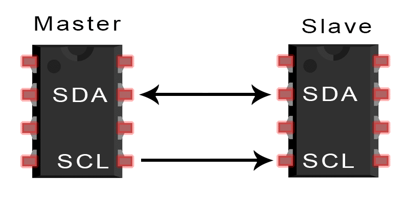
So I start with I2C (a.k.a Two wire interface).as i mentined in the introduction section i done some arduino hobby project . one is I2C interfaced Real Time Clock module,I2C interface 16x2 LCD module .. etc. so why I2C , like it's name it's only need two wire for commuication SDA :- Serial Data and SCL :- Serial Clock.
The I2C communication bus is very popular and broadly used by many electronic devices because it can be easily implemented in many electronic designs which require communication between a master and multiple slave devices or even multiple master devices. The easy implementations comes with the fact that only two wires are required for communication between up to almost 128 (112) devices when using 7 bits addressing and up to almost 1024 (1008) devices when using 10 bits addressing.
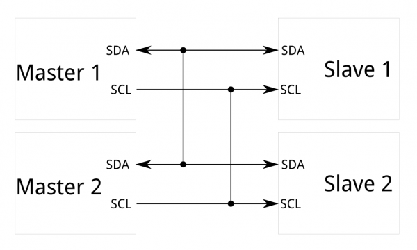
I2C requires a mere two wires, like asynchronous serial, but those two wires can support up to 1008 slave devices. Also, unlike SPI, I2C can support a multi-master system, allowing more than one master to communicate with all devices on the bus (although the master devices can’t talk to each other over the bus and must take turns using the bus lines).
I2C - A Brief History
I2C was originally developed in 1982 by Philips for various Philips chips. The original spec allowed for only 100kHz communications, and provided only for 7-bit addresses, limiting the number of devices on the bus to 112 (there are several reserved addresses, which will never be used for valid I2C addresses). In 1992, the first public specification was published, adding a 400kHz fast-mode as well as an expanded 10-bit address space. Much of the time (for instance, in the ATMega328 device on many Arduino-compatible boards) , device support for I2C ends at this point. There are three additional modes specified: fast-mode plus, at 1MHz; high-speed mode, at 3.4MHz; and ultra-fast mode, at 5MHz.(source :- sparkfun)
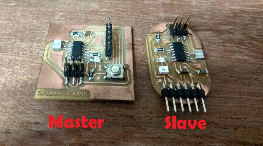
So we can start with I2C Communication Protocol, before milling a new board i tried with my existing Hello Echo and my friend jacob board.my plan is to control the slave led light using the master board, so here am using Hello echo board as my Master because it have a on-board button and i used my friend jacob board as slave because it have on-board led.
In ATtiny44 datasheet we can see the Two-wire Mode Operation, Simplified Diagram in page number 122.
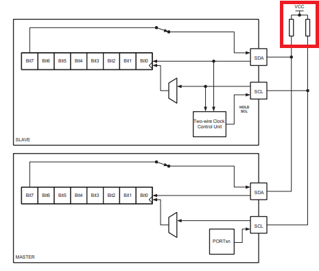
In here we see a Pull-Up resistor between Slave and Master SCK and SDA. it's because the I2C bus drivers are “open drain”, meaning that they can pull the corresponding signal line low, but cannot drive it high. Thus, there can be no bus contention where one device is trying to drive the line high while another tries to pull it low, eliminating the potential for damage to the drivers or excessive power dissipation in the system. Each signal line has a pull-up resistor on it, to restore the signal to high when no device is asserting it low.so here i used two 10 k SMD resistor .
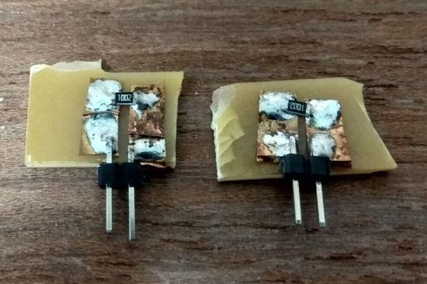
For the pull-up resistor i just used copper sheet and a male header.and i used breadboard for the connection.
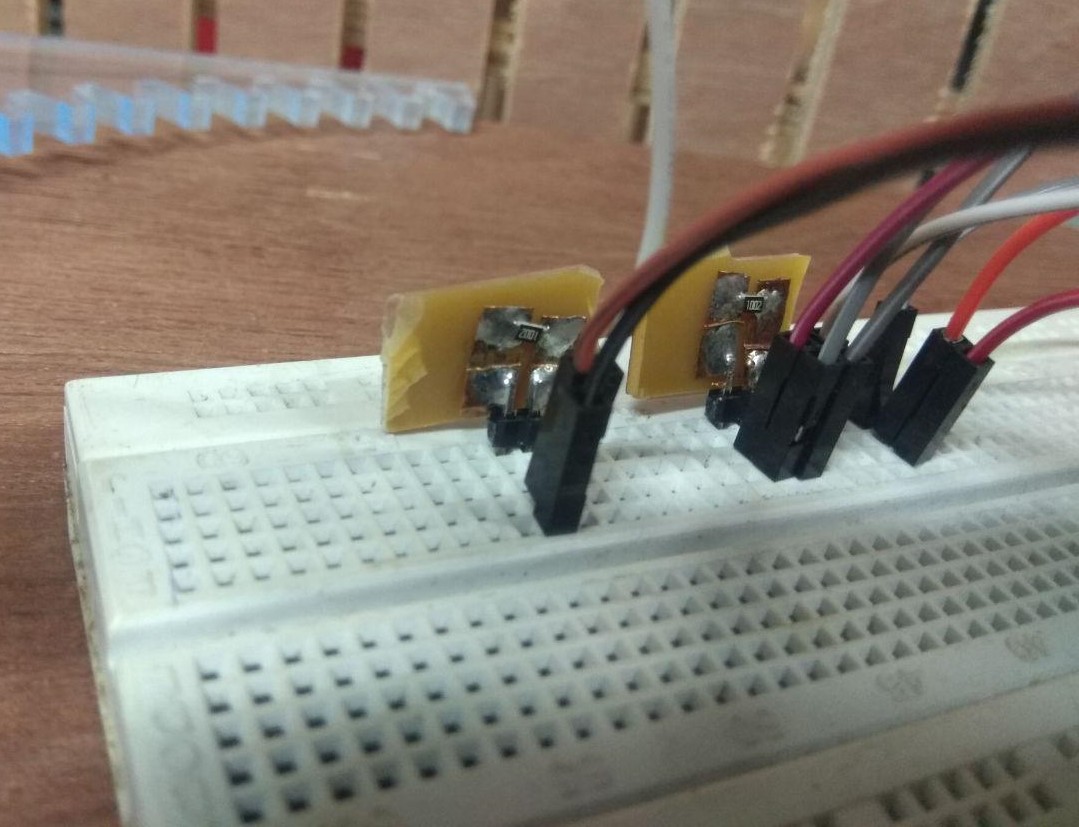
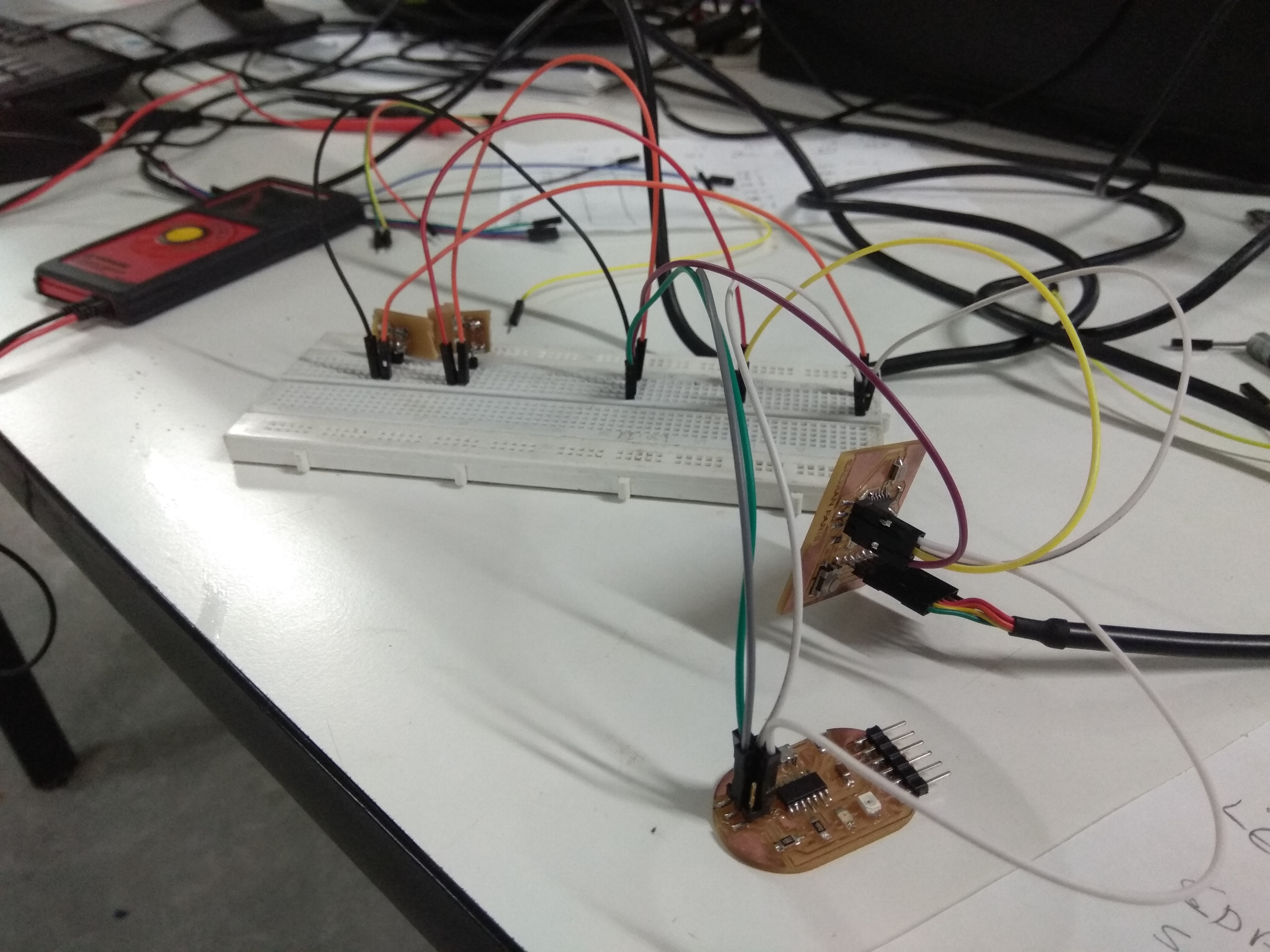
It's look like mess , but believe me it will work. here i used ISP pin MOSI for SDA and SCL for SCK.
First i tried with Arduino offical Wire.h I2C library ,but it only throw some compailation error ,after googling and researching i got TinyWire.h library. it's not worked that i expected next i used a new ATtiny board manager called ATTinyCore here is the git repo :- https://github.com/SpenceKonde/ATTinyCore . and agin i used the Wire.h library and the compailation was succeed .and the new board manager will gave us more control in our ATtiny Board.
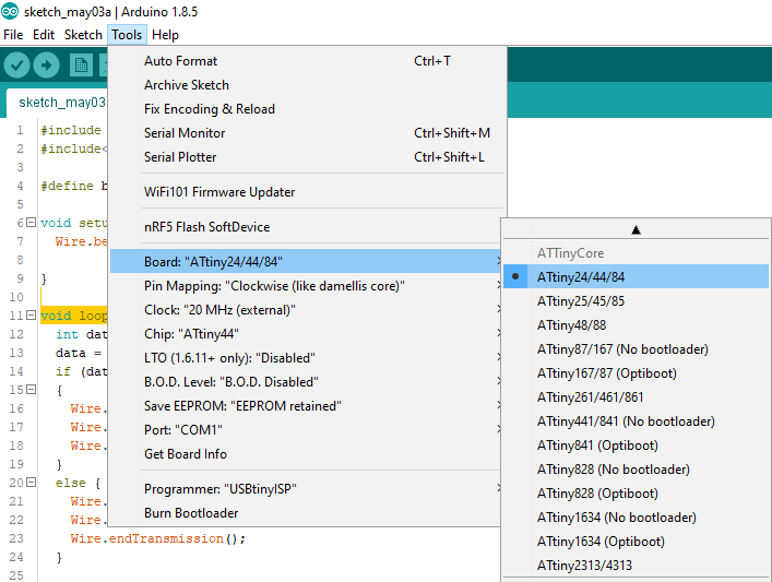
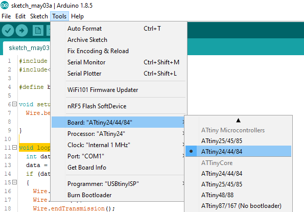
first one is the new ATtiny Core and second one is the ATtiny board definition ,and we can see we will get more control in microcontroller by using the ATtinyCore board definition.
Code
- Master Code
#include <Wire.h>
#include<SoftwareSerial.h>

#define button A2

void setup() {
  Wire.begin();

  pinMode(button, INPUT);

}

void loop() {
  int data;
  data = digitalRead(button);
  if (data == 1)
  {
    Wire.beginTransmission(8);
    Wire.write(1);
    Wire.endTransmission();
  }
  else {
    Wire.beginTransmission(8);
    Wire.write(0);
    Wire.endTransmission();
  }

}
}
#include <Wire.h>

#define led A3

void setup() {

  Wire.begin(8);
  Wire.onReceive(receiveEvent);

  pinMode(led, OUTPUT);

}

void loop() {
  delay(100);
}

void receiveEvent(int howMany) {

  int x = Wire.read();
  if (x == 1)
  {
    digitalWrite(led, HIGH);

  }
  if (x == 0)
  {
    digitalWrite(led, LOW);

  }
}
here we used receiveEvent as a event so here the function that executes whenever data is received from master.
Demo Video
Now we can design new Master and Slave board.
PCB Design
Master
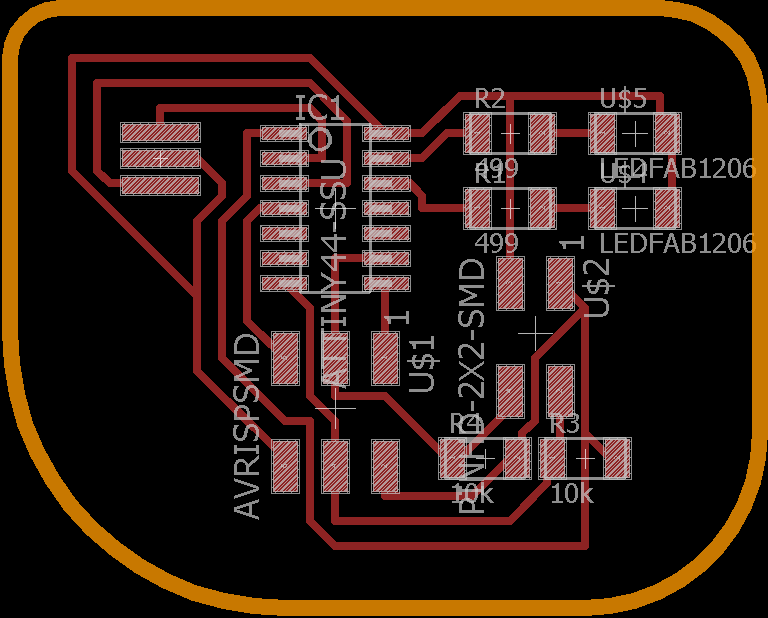
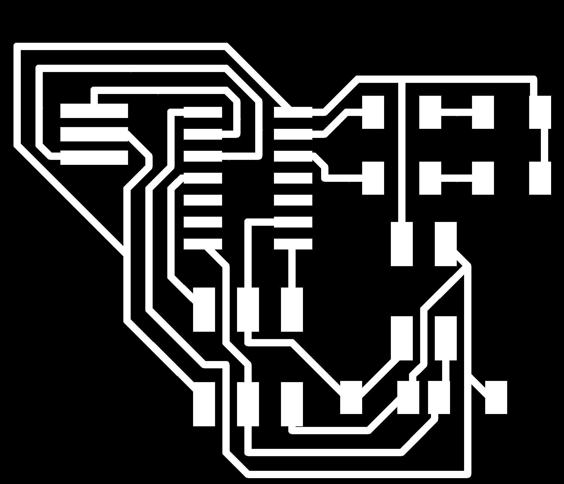
For the I2C network we need to Design Two boards . one is Master Board and another one is Slave board.first i designed Master board with ATtiny44 .
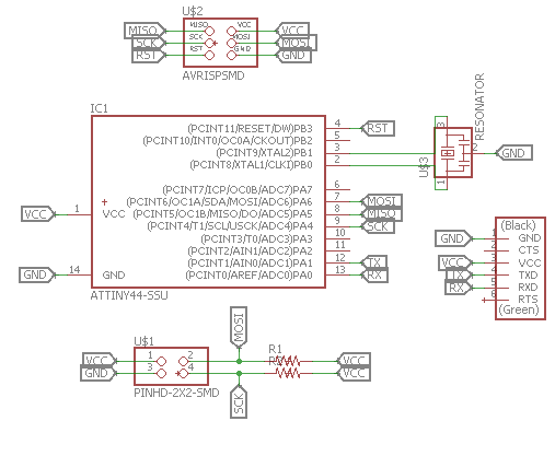
here i used ATtiny44 with 20 Mhz resonator. and also added 10 k ohm resistor between MOSI (SDA) and SCK.
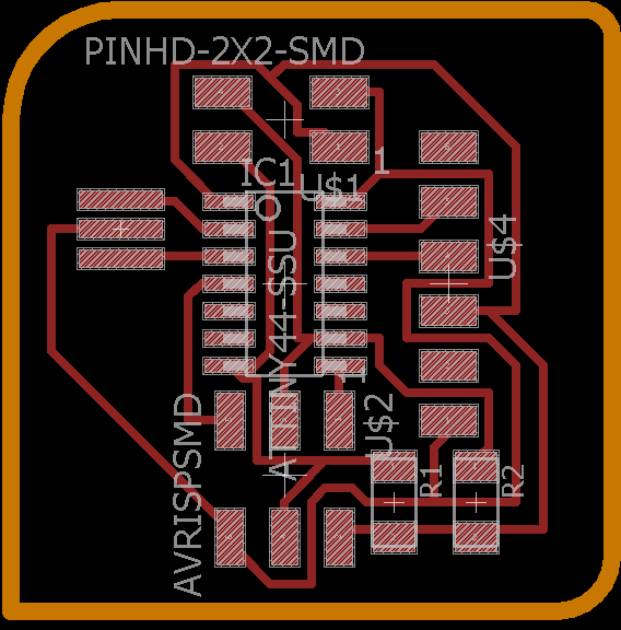
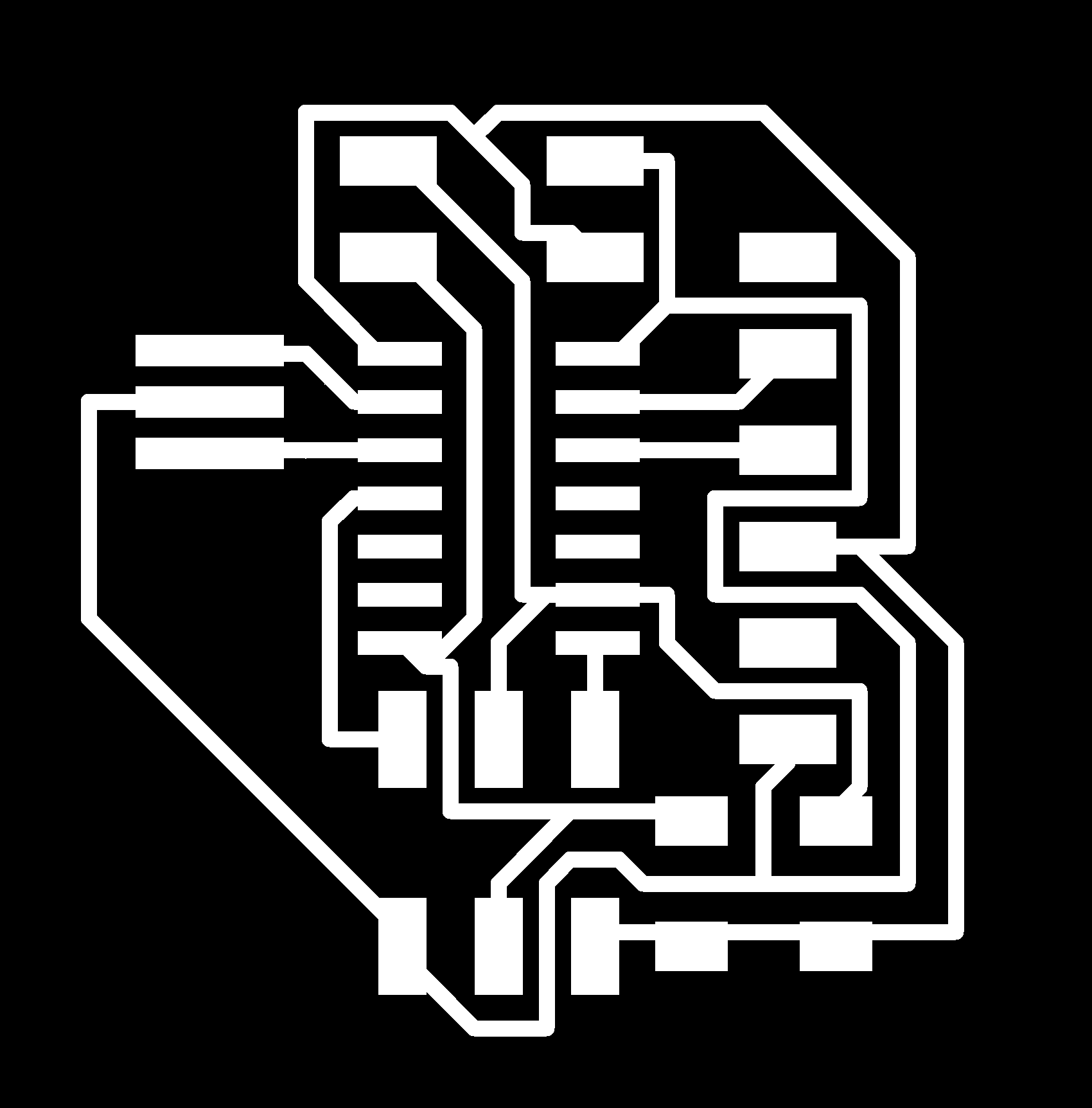
This is my board layout .after that i exported the image for milling and cutting.

Slave
For the I2C slave i used ATtiny44 with 20 mhz resonator and two LED's. i milled two slaves with same config.
In the slave i also added 10 k pull-up resistor for MOSI (SDA) and SCK.
This is my board layout .after that i exported the image for milling and cutting.

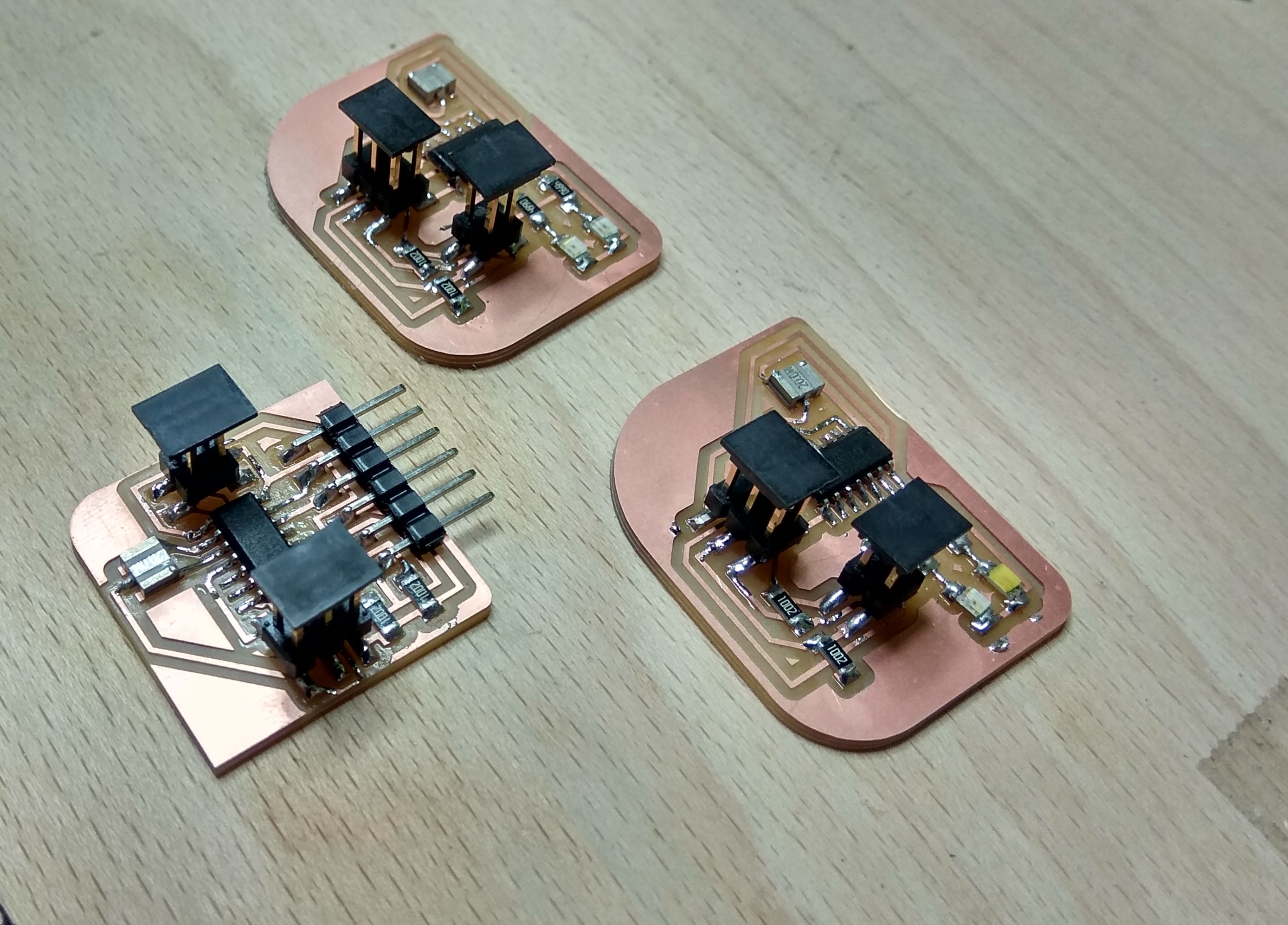
Milling and Soldering
Hero Shot
Progarmming
I used Fab ISP to programme the Master and Slave boards.
Master code
/*
 * Name :- ATtiny44 I2C Master
 * Author :-  Salamne Faris
 *
 */
#include <Wire.h>
#include<SoftwareSerial.h>
#define Rx 1
#define Tx 0
SoftwareSerial myserial(Rx, Tx);

void setup() {
  Wire.begin();
  myserial.begin(9600);
}

void loop() {
  char d;
  if (myserial.available() > 0)
  {
    d = myserial.read();
    if (data == '1') {
      Wire.beginTransmission(1);
      Wire.write(1);
      Wire.endTransmission();
      myserial.println("send :- ");
      myserial.print(data);

    }
    if (data == '2') {
      Wire.beginTransmission(1);
      Wire.write(2);
      Wire.endTransmission();
      myserial.println("send :- ");
      myserial.print(data);

    }
    if (data == '3') {
      Wire.beginTransmission(2);
      Wire.write(3);
      Wire.endTransmission();
      myserial.println("send :- ");
      myserial.print(data);

    }
    if (data == '4') {
      Wire.beginTransmission(2);
      Wire.write(4);
      Wire.endTransmission();
      myserial.println("send :- ");
      myserial.print(data);

    }

  }
}
Here i used Address 1for slave one and Address 2 for slave 2 . and
here we used receiveEvent as a event so here the function that executes whenever data is received from master.
Slave One Code
/*
 * Name :- ATtiny44 I2C Slave One
 * Author :-  Salamne Faris
 *
 */
#include <Wire.h>

int led1 = A0;
int led2 = A1;

void setup() {
  Wire.begin(1);
  Wire.onReceive(receiveEvent);

  pinMode(led1,OUTPUT);
  pinMode(led2,OUTPUT);
}

void loop() {
  delay(100);
}


void receiveEvent(int howMany) {
  int x = Wire.read();
  if (x == 1)
  {
    digitalWrite(led1,HIGH);
    digitalWrite(led2,LOW);
  }
  if(x ==2)
  {
    digitalWrite(led1,LOW);
    digitalWrite(led2,HIGH);
  }

}
Slave Two Code
/*
 * Name :- ATtiny44 I2C Slave two
 * Author :-  Salamne Faris
 *
 */
#include <Wire.h>

int led1 = A0;
int led2 = A1;

void setup() {
  Wire.begin(2);
  Wire.onReceive(receiveEvent);

  pinMode(led1,OUTPUT);
  pinMode(led2,OUTPUT);
}

void loop() {
  delay(100);
}


void receiveEvent(int howMany) {
  int x = Wire.read();
  if (x == 1)
  {
    digitalWrite(led1,HIGH);
    digitalWrite(led2,LOW);
  }
  if(x ==2)
  {
    digitalWrite(led1,LOW);
    digitalWrite(led2,HIGH);
  }

}
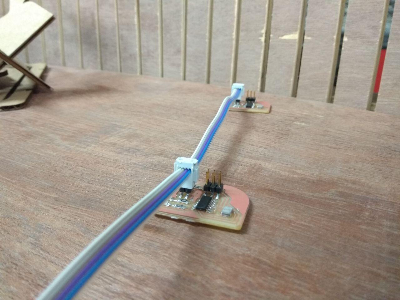
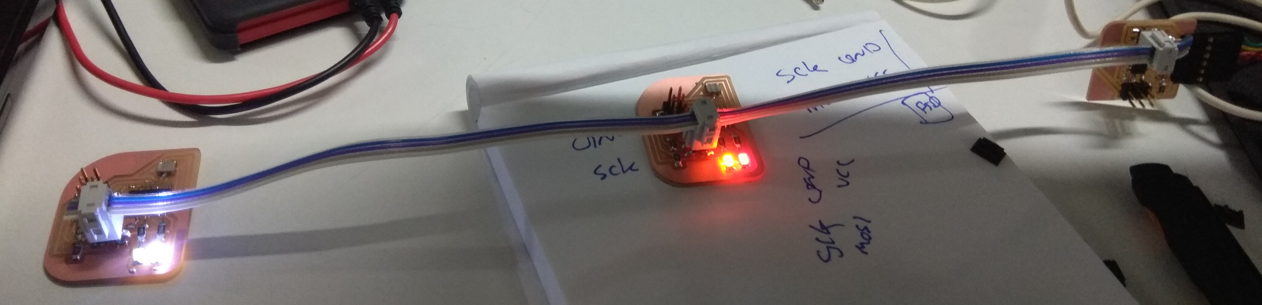
Slave master Connection
I used 2x2 Pin header with Rainbow cable to make a communication Bus.
Demo
First i uploaded code for turn on all the led in slave.
Video
Problems
I uploaded my code to slave and master board and it's work perfectly but after i changed one of my slave code and uploaded it throwed a error.
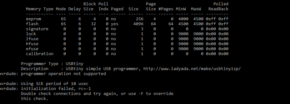
I try to override using -F.
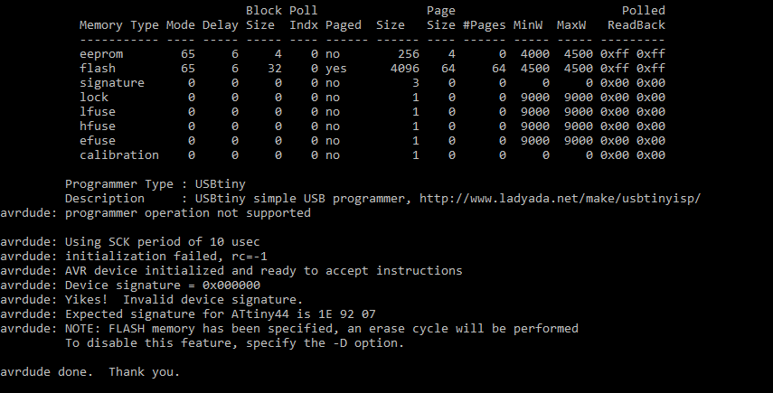
now we know problem , it was the Invalid Device Signature . i googled about the error and did't not found any solution and in AVR Freaks some one have the same problem ,he solved by just heating the ATtiny44 and ISP pin , so it's due to loosed/cold solder ,so i heated the solder on the ATTiny and ISP Pin header.Now problem solved .