See how to best use this week to help complete the final project, as well.
Go through FabAcademy Tutorial, Micky's Documentation, and Adrian's Documentation
Design Servo Enclosure[For final project].
Design a minimalist PCB to run a servo motor
See how to connect two distinct, disconnected PCBs
Tools:
Fusion 360
Autodesk Eagle
OnShape
I was away from Lab this week, too, due to covid uncertanities
Of all the weeks that will help me complete my final project, this is the most directly connected. Final Project: A Home Automation project that actuates household switches with a servo motor.
I started it off by going through Adrian's DocumentationAdrian Torres
This is by far the best article I have read on the topic - here
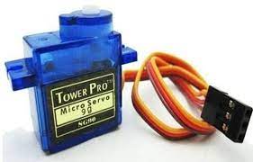
Servo Motor:
In the most generic sense, a "servomechanism" (servo for short) is a device that uses feedback to achieve the desired result.
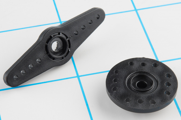
RC servos are reasonably standardized - they are all a similar shape, with mounting flanges at each end, available in graduated sizes. Servos often come with several wheels or levers, known as "horns", than can be attached to the shaft, to fit the device they are operating.
servos use a standard type of 3-pin plug
Control Signal:Servos are controlled with a specific type of pulse train signal. The pulses occur at a 20 mSec (50 Hz) interval, and vary between 1 and 2 mSec in width. The Pulse Width Modulation hardware available on a microcontroller is a great way to generate servo control signals.
Common servos rotate over a range of 90° as the pulses vary between 1 and 2 mSec -- they should be at the center of their mechanical range when the pulse is 1.5 mSec.
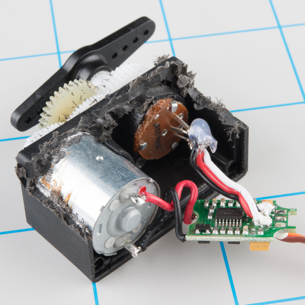
Internally, the mechanism of a servo motor uses a potentiometer attached to the rotating shaft to sense the position. It measures the width of the incoming pulse, and applies current to the motor to turn the shaft correspondingly.
The other side of the PCB has some transistors in an H-bridge configuration, which allows the controller to steer current through the motor in either direction, for both clockwise and counterclockwise rotation.
Ordinary RC servos turn over a 90° range -- it's useful for turning a steering linkage, or adjusting the control surfaces on an airplane, but not so useful as a drive mechanism. That's where full or continuous rotation servos come in.
But Since I need very limited range for my final project, I have no use for it.
Started going through the ATTiny85 Datasheet for timer - here
This YT Video helped a lot, so did this Electronics Stackexchange Q.
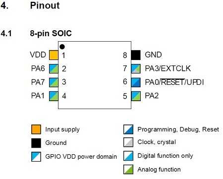
After a long discussion with my friend Saheen, I have decided that I will use ATTiny412 1-Series MC.
Then started a 6hrs+ read of various articles, documentations, datsheets, video transcripts, previous year documentations...
We are currently in a lockdown, and I will get back to fabricating it, once I reach the lab. Thanks.
After Reaching The Lab:
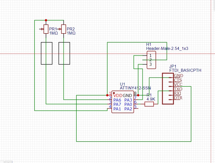
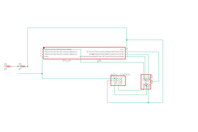
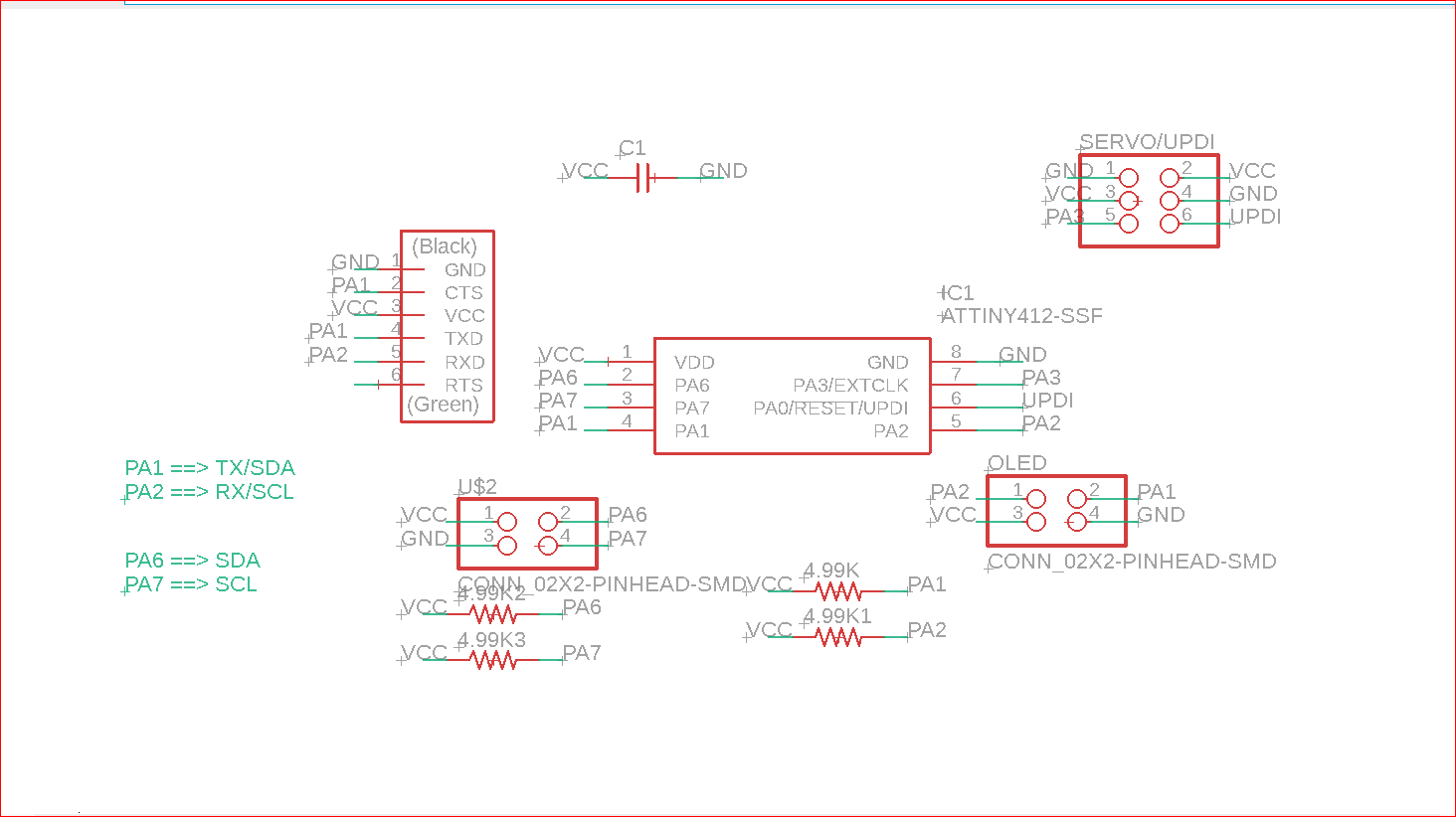
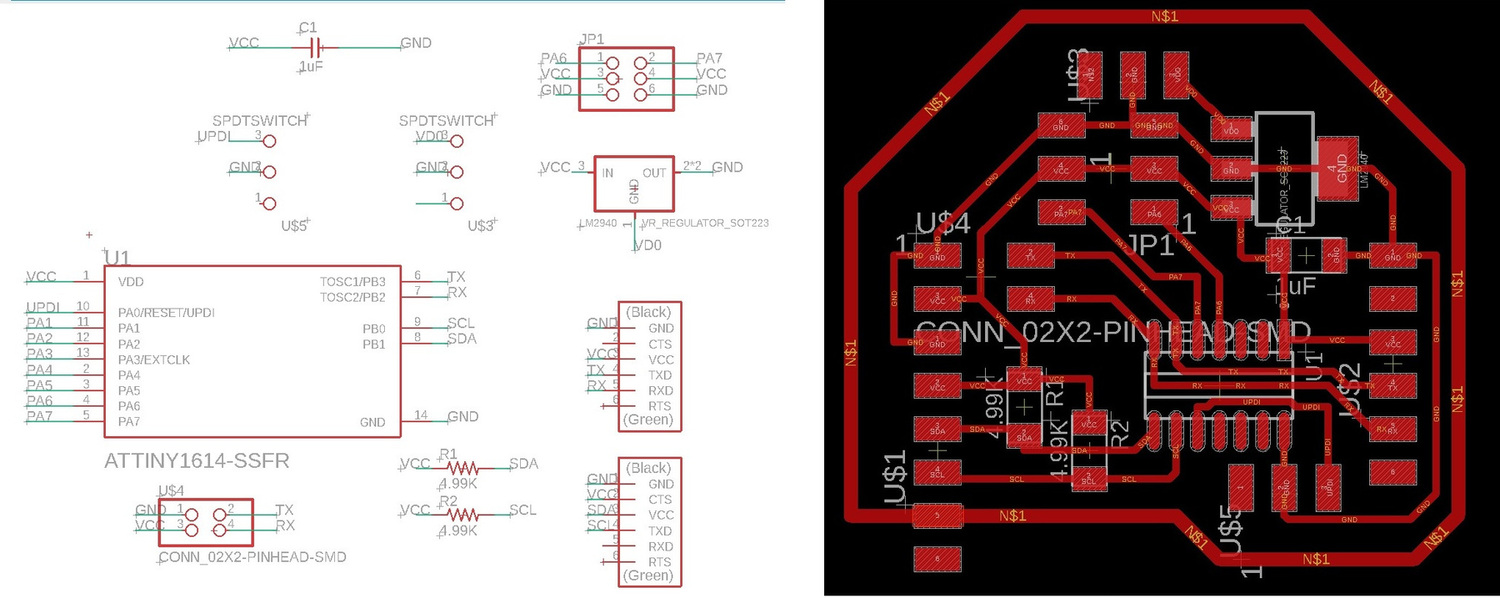
Schematic:
Reasoning:
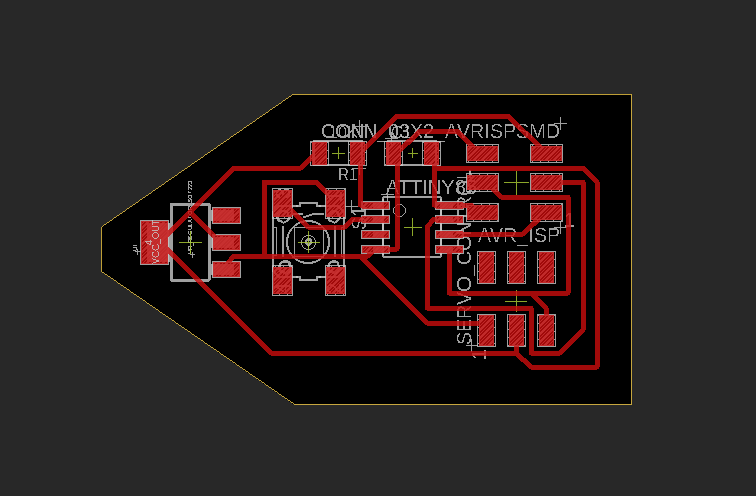
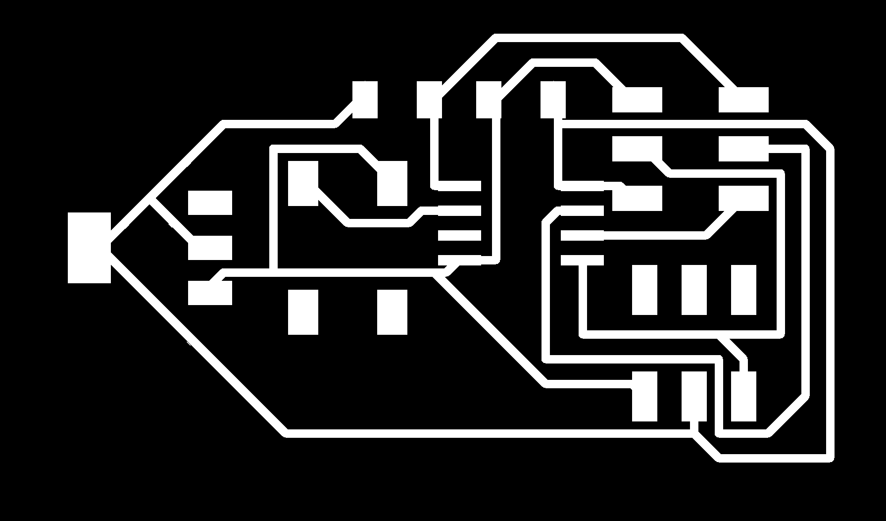
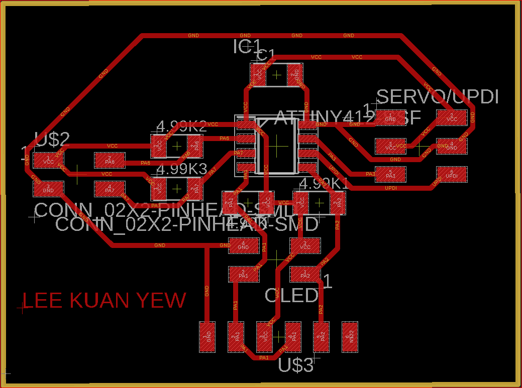
Board:
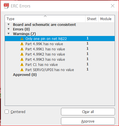
Trivial ERC Errors:
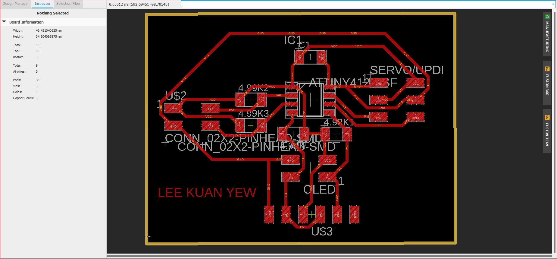
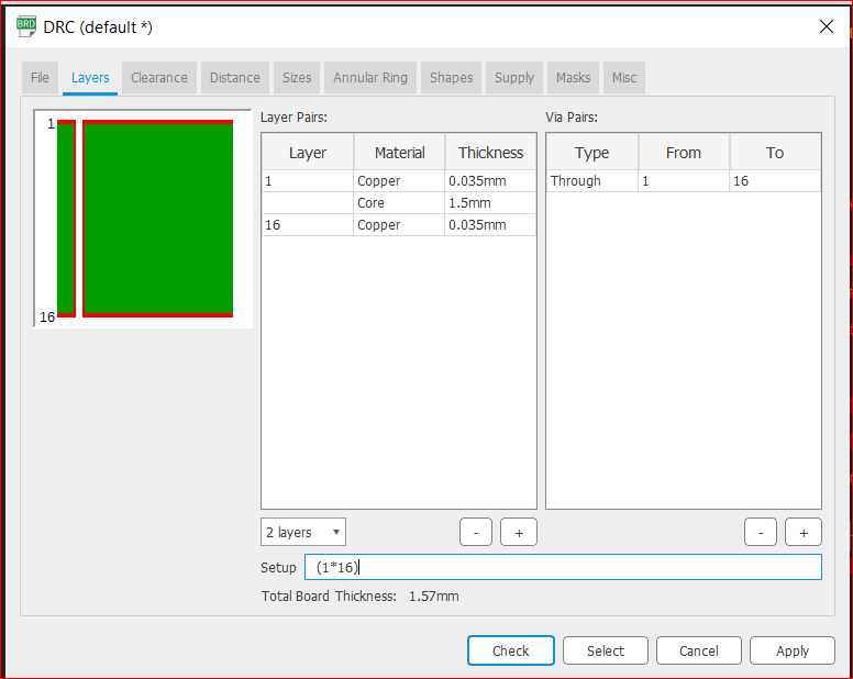
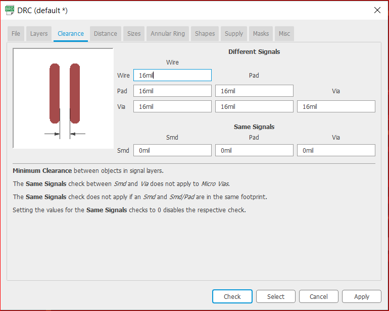
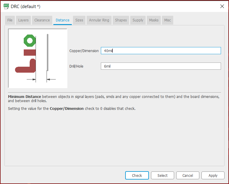
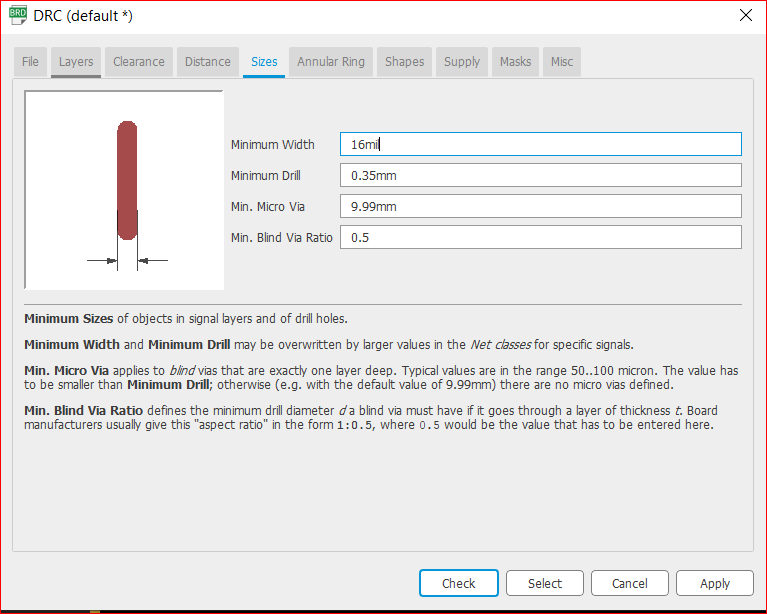
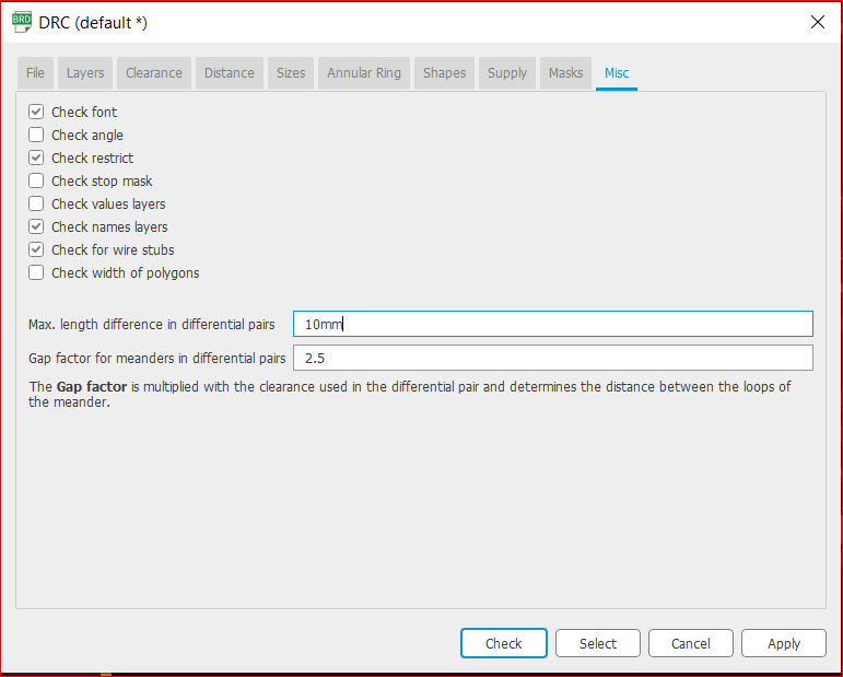
DRC:
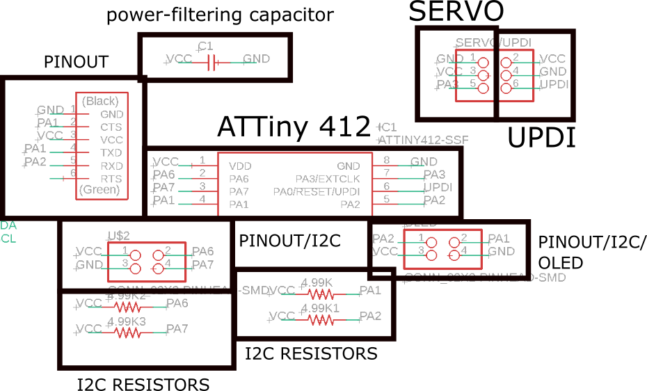
Image for Reference:
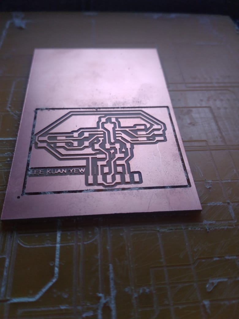
Traces:
Outline:
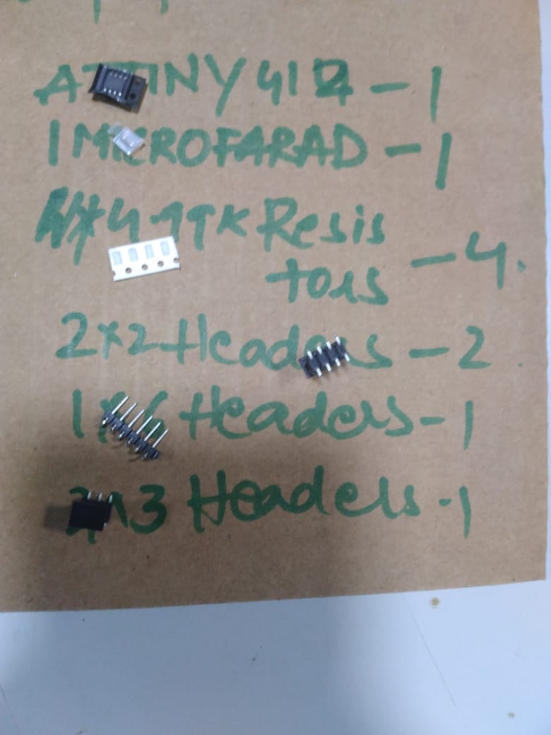
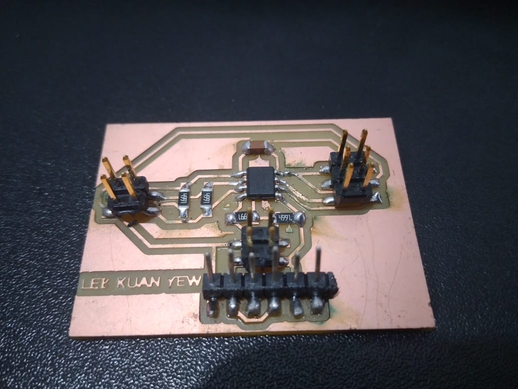
Fabrication:
Programming:
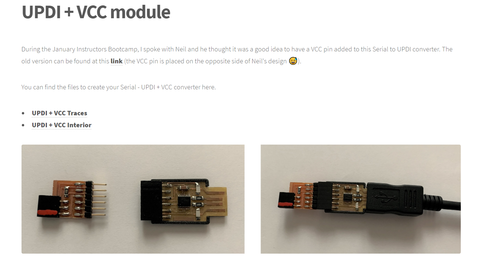
I programmed my microntroller using UPDI pin, with the help of megaTinyCore library, and I used UPDI + VCC module.
Output Devices, I tried:
Servo
LCD
Servo:
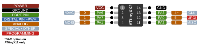
To control a servo, we need a GND, VCC, and a Analog Pin. Maximum Voltage of my servo is 6v.
            #include

              Servo servo;

              int pos = 0;
              int pin = 1;

              void setup() {
                servo.attach(pin);
              }

              void loop() {
                for (pos = 0; pos <= 180; pos += 1) {
                  // in steps of 1 degree
                  servo.write(pos);
                  delay(15);
                }
                for (pos = 180; pos >= 0; pos -= 1) {
                  servo.write(pos);
                  delay(15);
                }
              }
Connect Servo Pin to PA7 Pin, which maps to Arduino "1".
LCD:
The LCD 2004A can be controlled by either I2C or SPI, I chose I2C. Therefore, we need 2 more pins apart from SCL and SDA. LCD 2004A needs 5v-10v. It has 4 rows, and 20 columns.
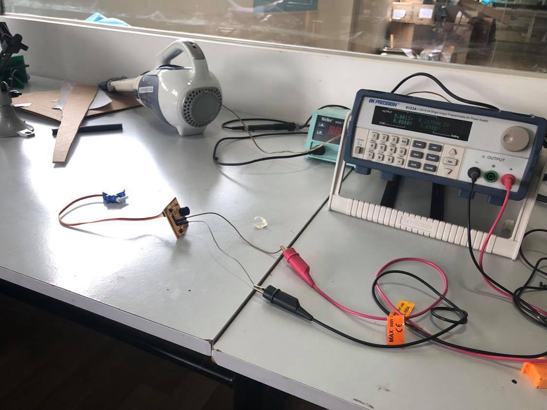
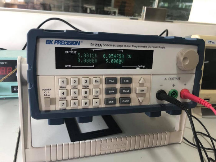
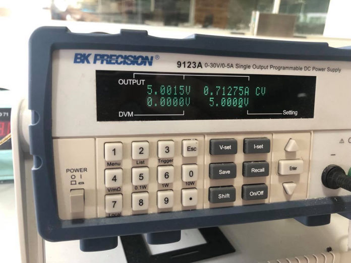
For the group assignment, we used our colleague's output devices board to measure its power. The following code was used to see the difference in current and then calculate the power consumption of both the connected servo and buzzer.
 Credit:here
od.png)


