Week 5. 3D Scanning and Printing
week 5 Group assignment is to test the design rules for your 3D printer
3D Printing
3D printing is an additive manufacturing technology which recently get world's attention.For the past 10 years 3D printing grew a lot because of the open hardware world.so,this is an additive type manufacturing method which is done by adding materials technique.for prototyping and product development designing the 3D printing is very helpful we can almost print anything even complex structures,real homes etc...
there are many type of 3D printing technologies available.Each invented for different different purposes.There is a printer available to print bio organs also another printers available to build working rocket engine's nozzles ,nowadays people are using the technology to perform beyond our imagination.
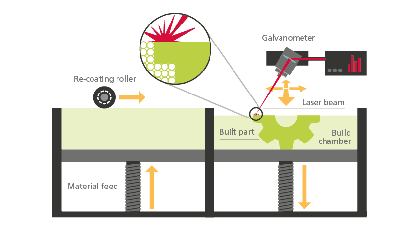
Selective Laser Synthesis(SLS)
This type of 3D printing technology uses for industrial purpose.It use a laser beam to fuse powdered material practical selectively . The materials are mostly high melting temperature plastics like nylon and some metals.so a roller fill the powder in the bed cavity layer layer . See the picture below
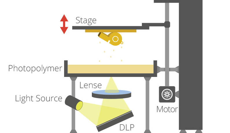
Stereolithography Apparatus(SLA/DLP)
SLA and DLP technologies have similar working method,each doing with a photo curable liquid resin as the printing material.They use UV light or UV laser for cure the practicals together.A selective mechanism or a dlp projector is helps to point the laser or uv light to job layer by layer so the projection come from under the resin tray and the print bed/head moves up(z axis) from the resin tray
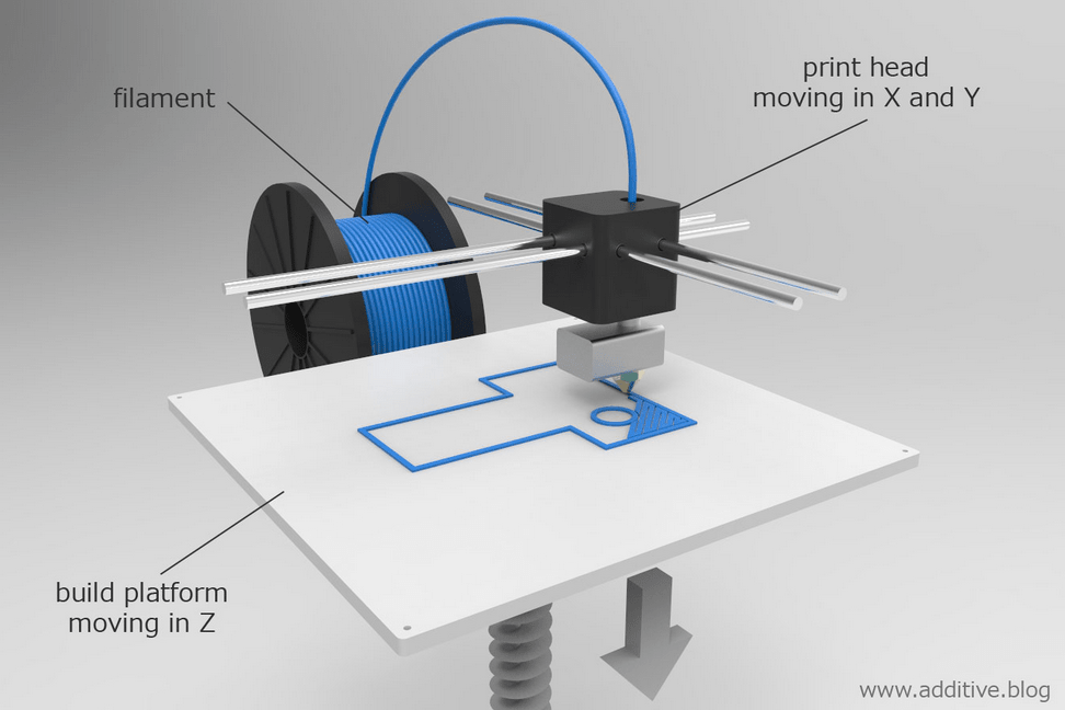
Fused Deposition Method(FDM) or Fused Filament Fabrication(FFF)
these are the cheapest 3D printing technology available to use like a plug and play device.like in the picture shown,it used a material reel fed by a controlled motor through a heated nozzle head which is controlled by two motors alongside x,y axis,so which can plot layers with respect to the moving z height controlled by another motor.
Ultimaker 2+ FDM 3D printer
So fab lab kochi has ultimaker 2+,It's a cartesian type FDM 3D printer for Fab academy
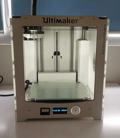
Ultimaker is one of the world biggest commercial 3d printer manufacturer with strong open source communities.The also makes the slicer software Program called Cura which is open source and free for all.
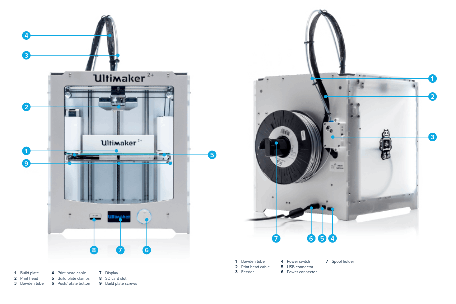
The above figure from Ultimaker 2+'s Guide shows the important body parts of the Ultimaker 2+ for using . For more click here to see the guide.
STL Slicer
3D printers are basically called CNC machines and it can only perform what we instruct to do in the form of G-codes. So in order to create G-code from a 3D file we use a software program called Slicer Program. there are many type of slicer programs available like Cura,simplify3D,Prusa slic3r,Slic3r etc...
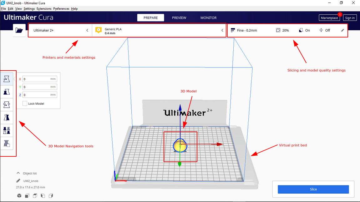
Ultimaker Cura is one of the best user friendly slicer tool which is open source and free to use. We don't want to set anything special to use the software because we are using the 3D printer also from ultimaker. So, just select the company ,printer model number and go and slice. For more refer this Tutorial from ultimaker.com
Test Print : Checking Design rules
In-Order to learn How to 3D print and knowing the machine limits,print tolerance or The design rules we have to print a test print which help us measure and find them.
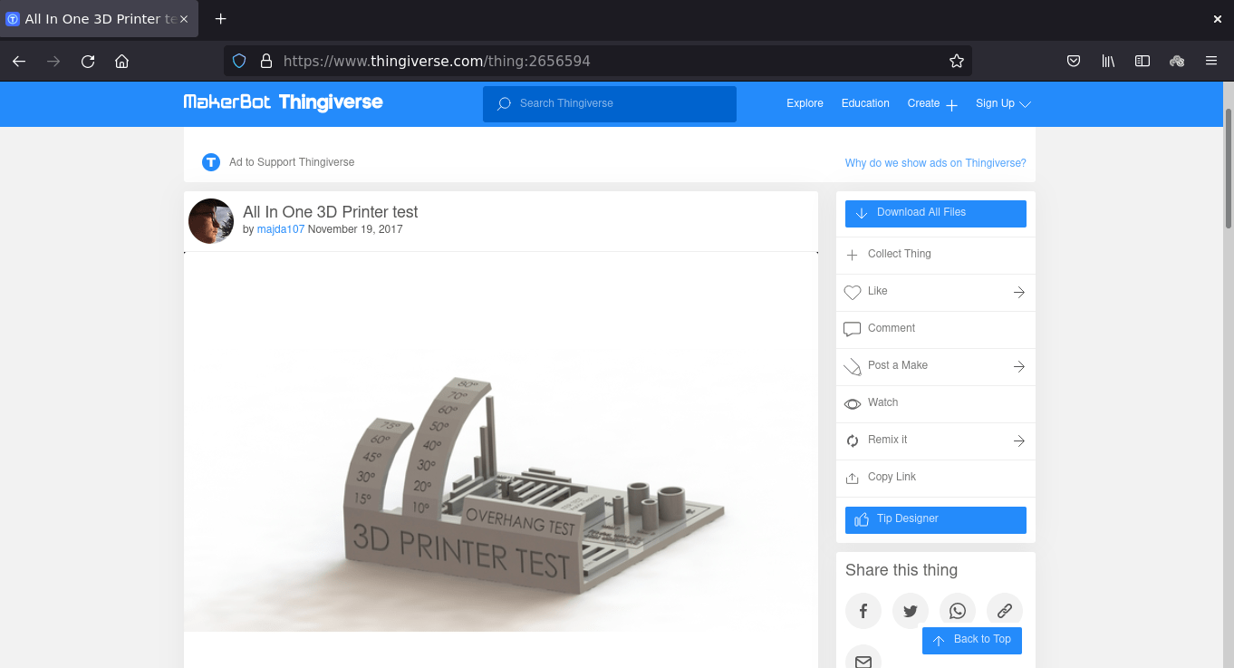
So we found a free '3D printer Test' File from Thingiverse.com which can be use full to know all the tolerance like over hang, shrinking x,y tolerance tower printing and bridge printing etc... Thingiverse is a website where we can get free and open source 3D printable files or Awesome projects.
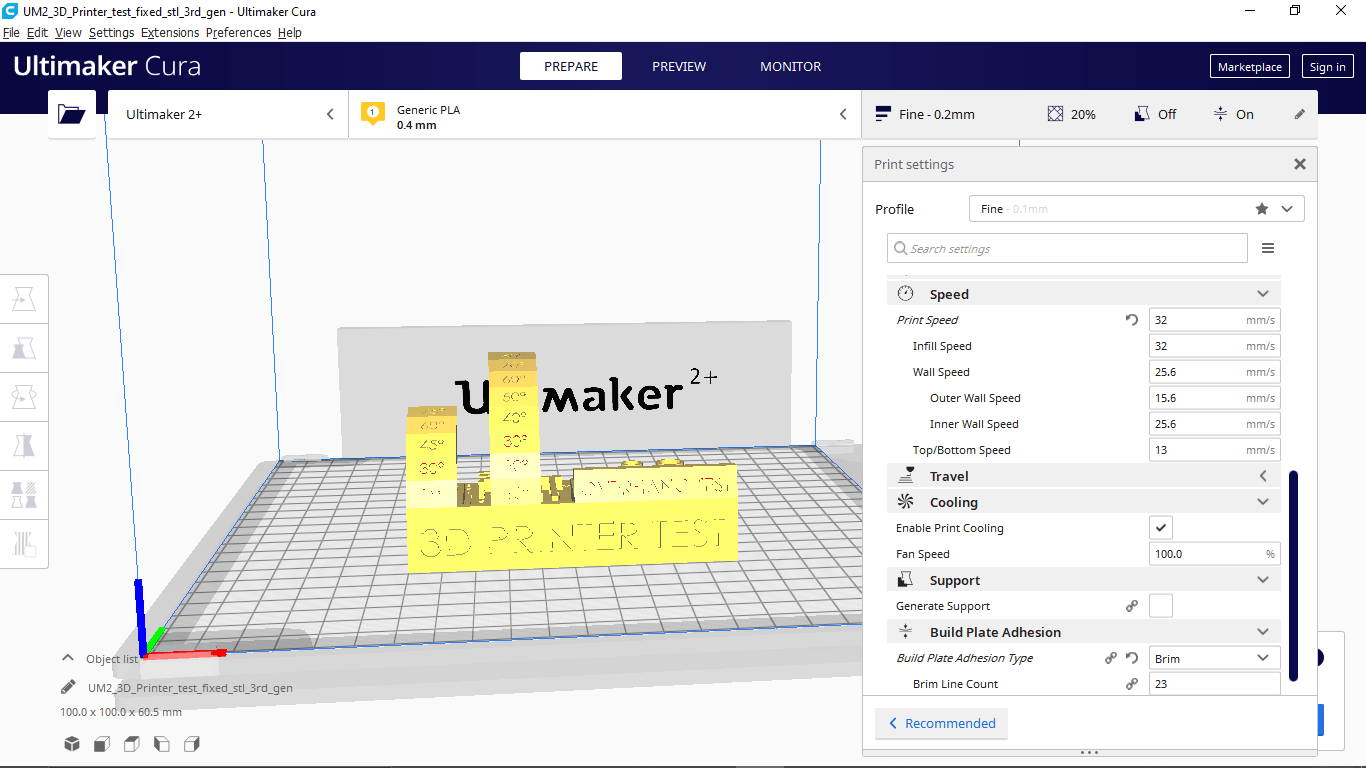
We downloaded the file from Thingiverse and loaded in Ultimaker cura then applied then Print setting without any support in 0.2 mm layer height and 20 % inner infill.
Layer height is the one which results the surface finish quality of the print it can be vary from 0.06 to 0.3 that depends the printer and it's hardware precision.
Infill is defined how much inside fill needs to make the print wright less or rigid while printing this infill print quality can be adjust from 0 to 100 % .There are various types of Infill pattern structure available for making the print structure more mechanical properties.
Cooling is a feature that helps to cool the printed part immediately after the print material came out from the nozzle which can be helpful while printing angled objects,bridges..etc.. .It is possible to adjust the fan speed from 1 - 100% depending on the print material cooling time we leaving it as 100% default for PLA.
Support is used for printing horizontal or angled object in mid air without touch ing the print bed .So the Printer will do thin wall pattern as a support structure beneath the model or part to be printed .The support can be removed by hand or with helps of some tools like knife,nose pliers ..etc..
Build Plate Adhesion.If the print is too small it wont be stick to the bed till the printing or the print bed finish Isn't that good ,In those case this feature can help us to give a Adhesion options like a 'Brim' of a tree which hold the print part without falling of the bed while printing. We selected 'Brim' for this print which is totally unnecessary for this model.
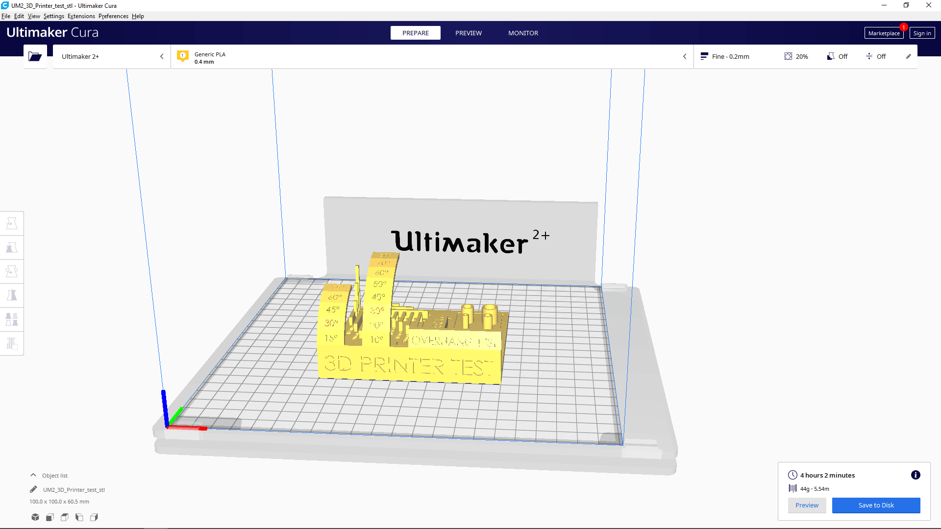
In the bottom corner it shows the time taken and material consumption after we clicked the slice button. If we click the preview shows a simulation of the 3d print layers by layer.
The above video shows how the preview looks like. It's possible to play a layer print head path to see how the print is gonna be.
before start printing we have to make sure the pinter's bed is leveled .so there is an printer settings to check the print bed is leveled or not.If the bed isn't leveled we can set the level using the bed adjust knobs and the rotary encoder of the printer.
The above video from Saxion FabLab Enschede youtube channel explains the whole Procedure of the Bed leveling in Ultimaker 2 3D printer
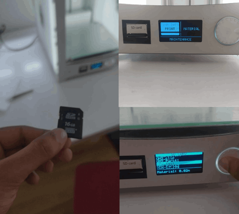
Then we saved The sliced G-code out put from cura software to a SD Card then inserted to the printer and selected Print options that shows the files saved to print.just hit the file name and confirmed to start.
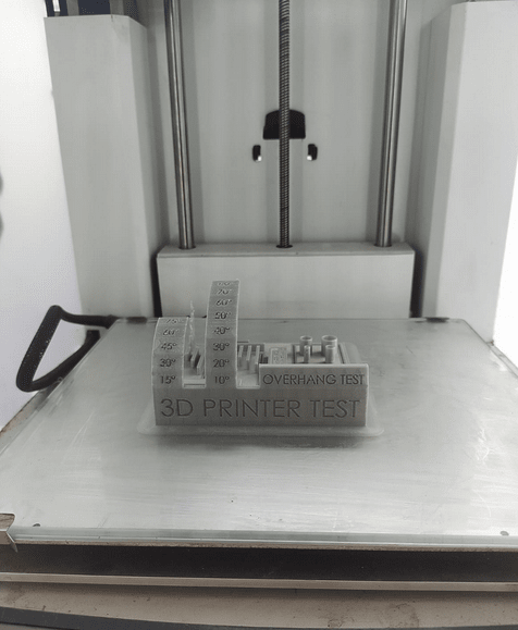
After a long 4 - 5 hour the print is finally completed and ready to take out from the Print bed.
Then we de-attached the glass bed from the printer and removed the printed Object by using a Edge scraper .It is important to make sure the bed is not in temperature while we take out from the printer.
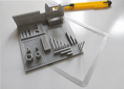
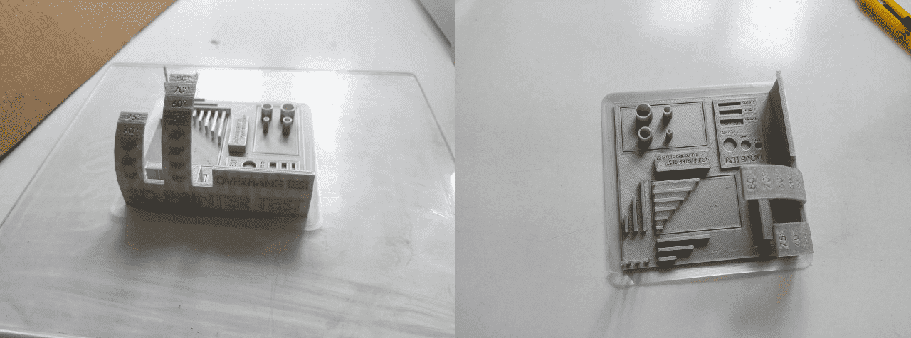
We cuts out the brim layer from the model using a pen knife. then we started to measure and inspect The printed object to understanding the print tolerance
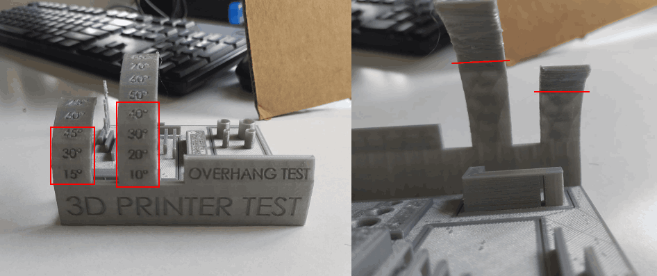
In the Over-hang print results Indicates that it's ok to print upto 45-50 degree angles without any supports and it's also possible to print upto 80 degree but may loose some features or will get a unfinished bottom(area under the angle). 45 is the best.
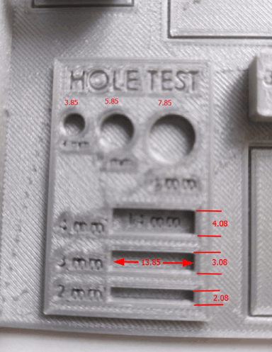
In the hole test we get a tiny error of 0.1 -0.15 along Y axis and 0.8 along X axis The differences we measured is given in the above picture.The machine is almost precise as 0.5 - 0.1 mm from the study
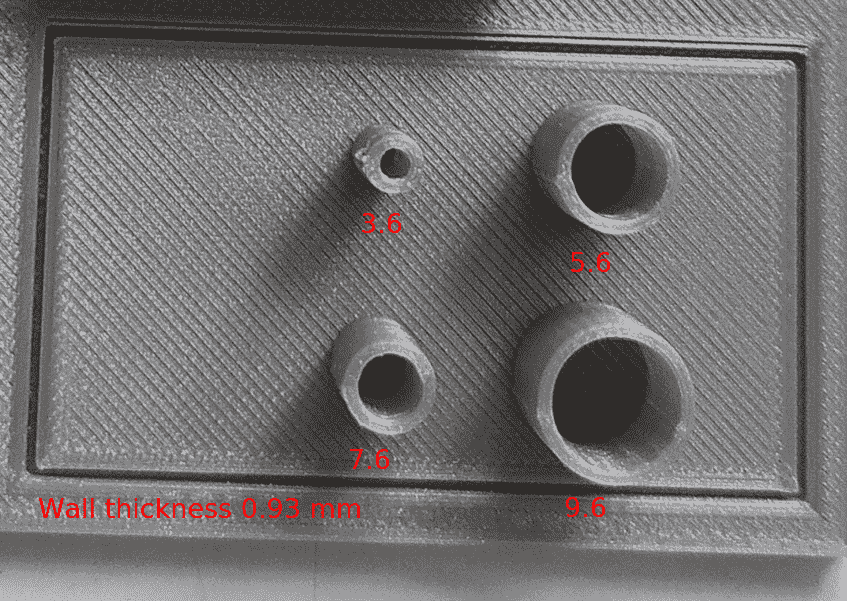
From the cylinder we got up to 0.4 mm differences from the actual dimension. It is probably happened because of the shrinkage of the material.
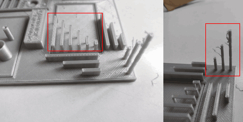
The bridges are printed without anu under support and just using the material cooling technique a Part cooling fan helps the printed material to cool immediately and as follows the bridges are possible without a nice finish It's better to avoid because it's not gonna same in other materials like ABS but PLA it's Ok with the part cooling fan . Also the tower printing was failed at a certain height and That's not a good Idea to print a small diameter tower like a shaft in a 3D printer
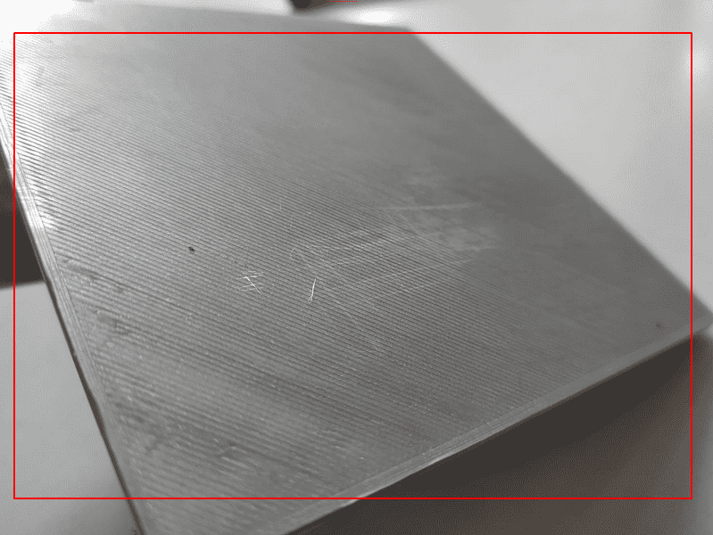
The bottom finish was came out like a glass finished surface because the print bed is made out of glass (Borosilicate glass may be). That's kind of cool for flat surfaces.This also depends each printer's bed technology
Our Observations are:-
- Overhang: Over hang of draft angle 45 degrees could be printed without support
- Bridge width of 25mm is possible without support and 100% cooling
- Max height for 2mm x 2mm column is 12mm
- For cylindrical holes: deviation in diameter=0.12
- For rectangular holes: X-deviation=0.08mm, Y-deviation=-0.15mm
- For thin extruded cylinders: deviation in thickness=0.2mm deviation in outer diameter=0.22mm
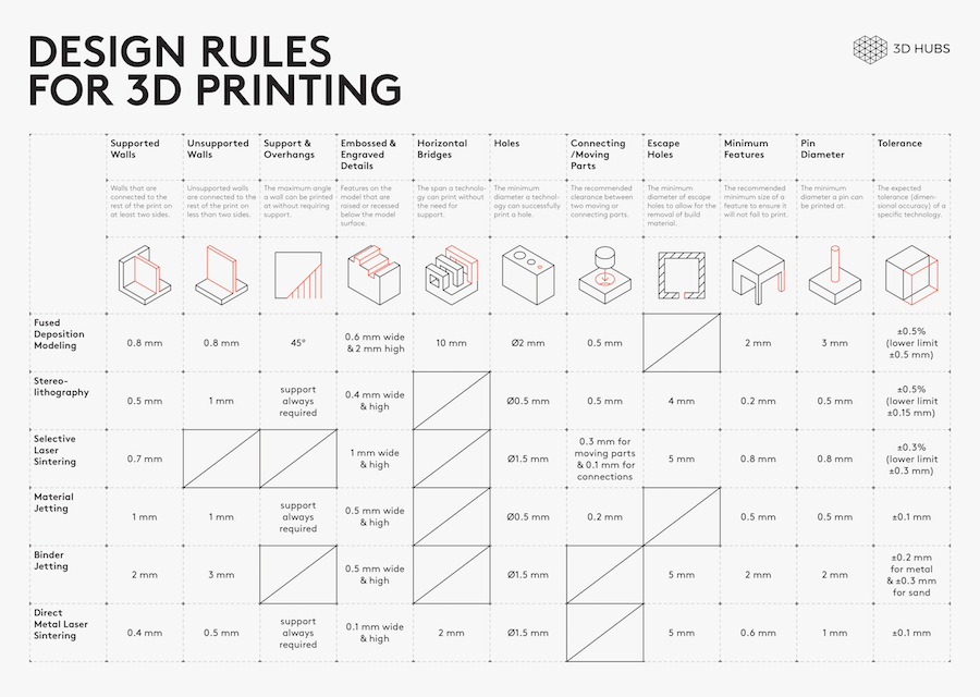
For more this Design rules table from hubs.com will helpful also refer this Tips and Tricks from The university of melbourne