WEEK 6 Electronics Design
Group Assignment
use the test equipment in your lab to observe the operation
of a microcontroller circuit board
This week’s group Assignment is written in here
Individual Assignment
redraw an echo hello-world board,
add (at least) a button and LED (with current-limiting resistor)
check the design rules, make it, and test it
extra credit: simulate its operation
Designing
I used EAGLE 9.6.2 education for designing the board.
Before I start designing,downloading the nesessary libraries is needed.The following are the libraries I downloaded this time.
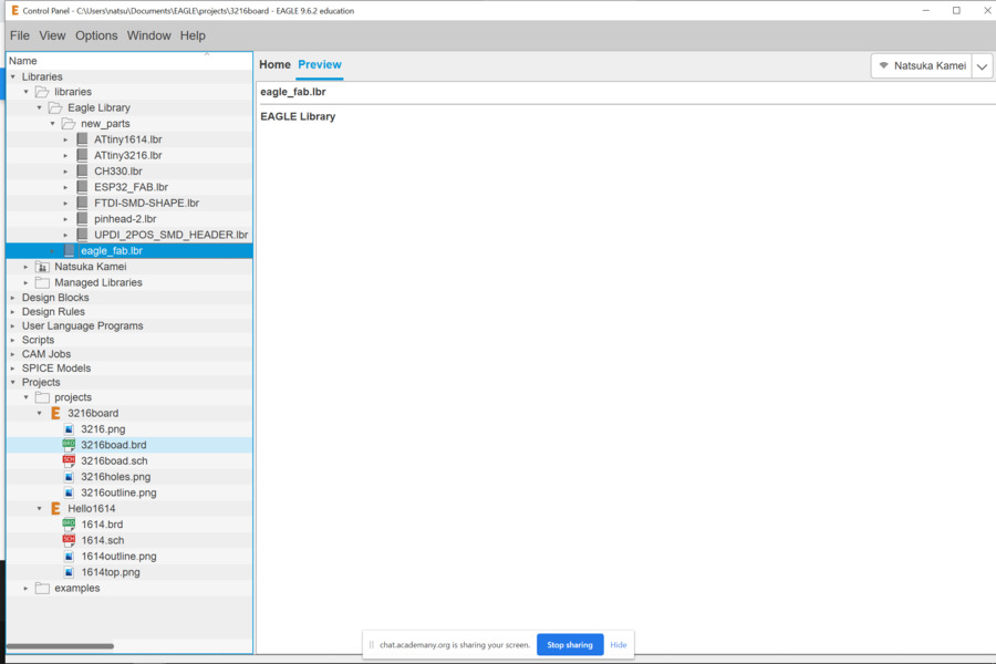
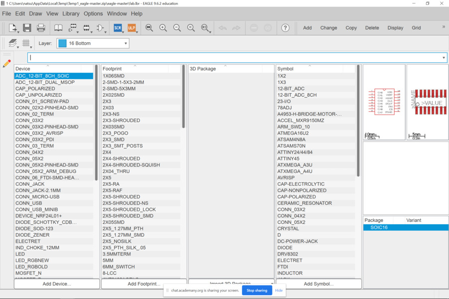
After downloading all libraries I needed, chose comportnents.
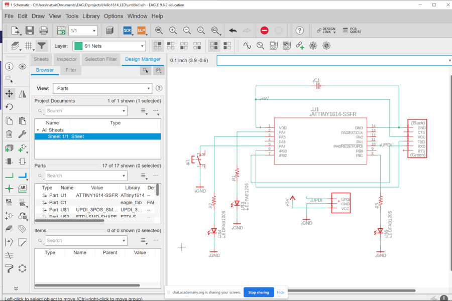
Schematic Design
Then, I could start Schematic designing.Procedure is as follows:
1.Creaate connections between each comportnents.
2.Use Move, Rotate, and Delete commands to adjust and redraw as nesessary.
Board Design
Once designing schematic has done, I move on to design the board(PCB). Procedure is as follows:
1.Open the "board" window to design it.
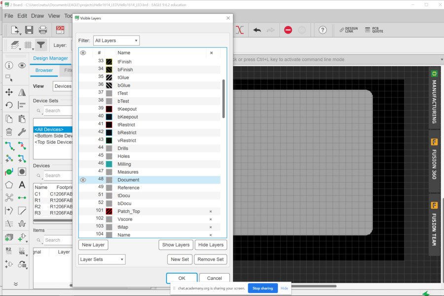
2.Set the design rules as follows from the tab edit > design rules > load.
3.Arrange all the components inside of the PCB board and drew the paths using the Route command.
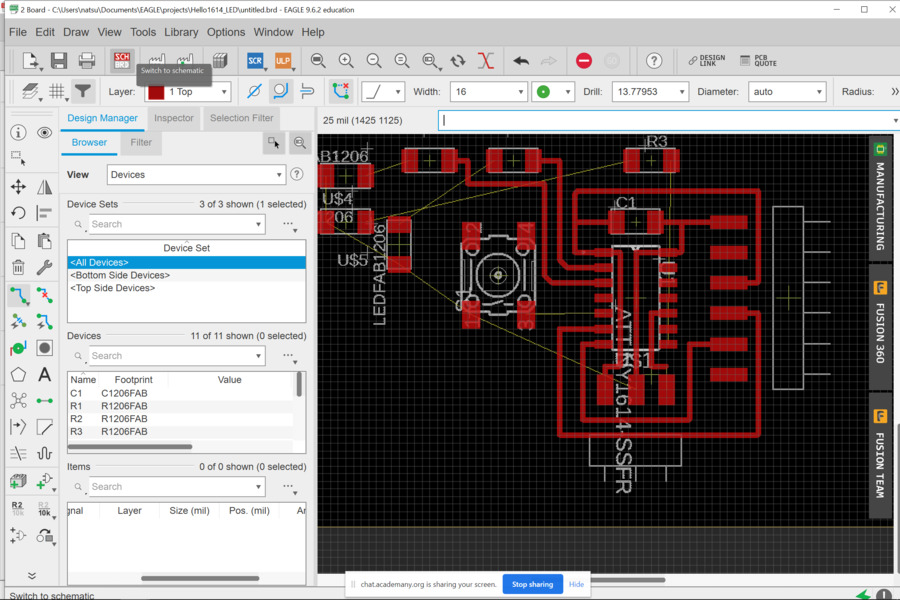
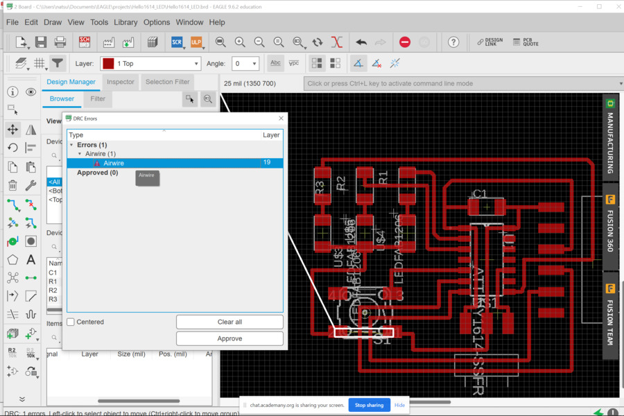
4.Check the design errors by uing Drc command.Fix them as nesessary.
5.Check "48.Document" layer and draw the outline with Polygon function.
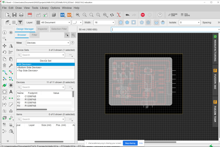
6.Export PNG file. Don't forget 800 dpi and actual size!
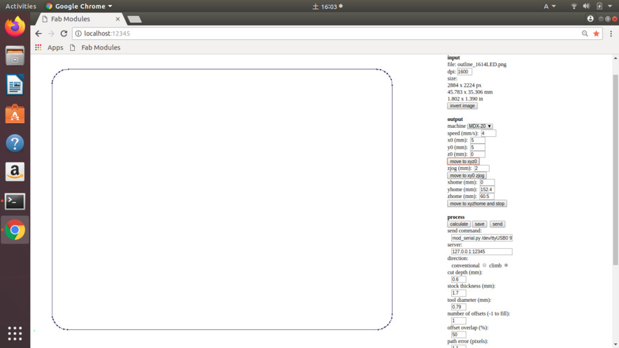
Generating Tool Pathes
Then I made tool pathes through Fab Modules to send milling machine.
For the inside data, I changed cut depth(0.1mm to 0.2mm)and dpi (800 dpi to 1600 dpi)
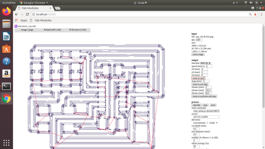
For the outline data, things I changed for the setting were cut depth(0.1mm to 0.6mm)and dpi (800 dpi to 1600 dpi)
Milling
Finally my favorite part, milling!
Soldering
I picked all compornents from Fablab Kannai inventory.
1 x ATtiny1614
1 x 1uF capacitor
3 x FTDI header
6 x UPDI header
1 x Switch
3 x 1k resistors
3 x LED(White Yellow)
Before the local session today I watched tutorial Youtube videofor soldering which my instructor shared. The tips I learned from the video are as below. They made my soldering struggles much better!
・ Use a non-oxidized iron tip.
・ Use a non-oxidized solder wick.
・ Cut used solder wick but remain a little bit solder on it so that it doesn't far apart.
・ Do not heat up the iron tip too much.
・ Do not pressure too much.
・ Separate the sodler wick and the tip in same time.
After soldering, I tested connections of paths with multimerer.
Programming
Work flow for programing were as follows:
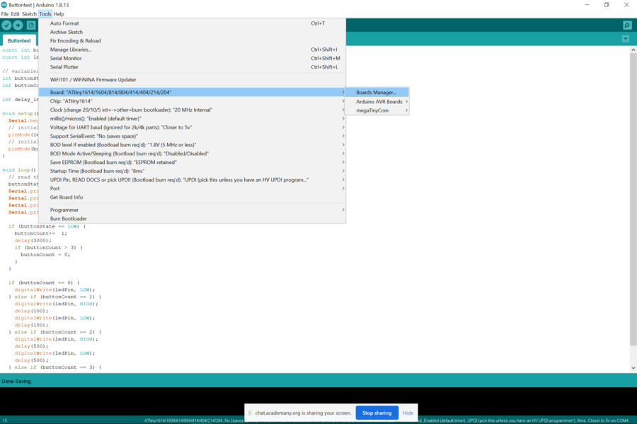
1.Check the environment to use Arduino IDE.
2.Load the Board Manager ATTinyCore.
Select Arduino -> preferences -> Additional Boards Manager URLs -> add http://drazzy.com/package_drazzy.com_index.json
Then select Tools -> Board -> Board Manager -> search 412 -> megaTinyCore -> version 2.2.5 or later.
3.Connect the boards through USB port.
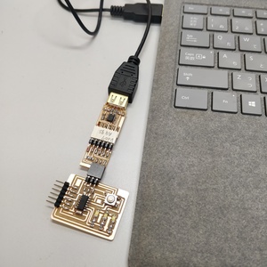
4.Check the connectiong between PC and the board.
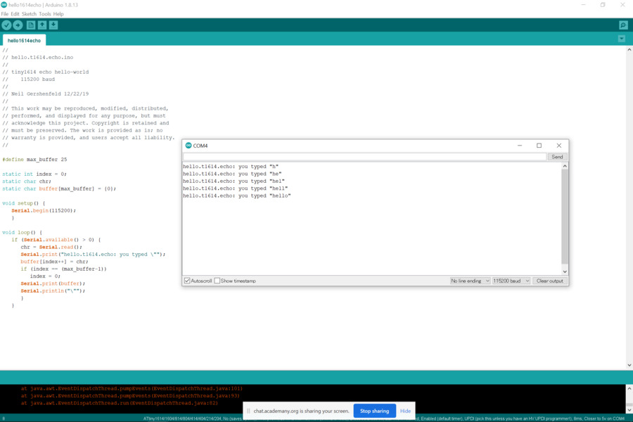
5.Try echo program.
  //
// hello.t1614.echo.ino
//
// tiny1614 echo hello-world
//    115200 baud
//
// Neil Gershenfeld 12/22/19
//
// This work may be reproduced, modified, distributed,
// performed, and displayed for any purpose, but must
// acknowledge this project. Copyright is retained and
// must be preserved. The work is provided as is; no
// warranty is provided, and users accept all liability.
//

#define max_buffer 25

static int index = 0;
static char chr;
static char buffer[max_buffer] = {0};

void setup() {
   Serial.begin(115200);
   }

void loop() {
   if (Serial.available() > 0) {
      chr = Serial.read();
      Serial.print("hello.t1614.echo: you typed \"");
      buffer[index++] = chr;
      if (index == (max_buffer-1))
         index = 0;
      Serial.print(buffer);
      Serial.println("\"");
      }
   }
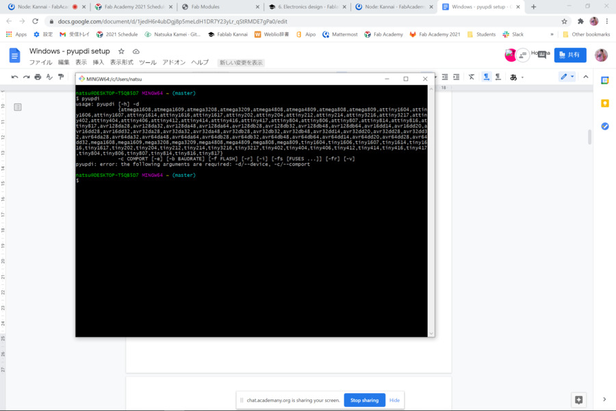
Problem
Unfortunatelly, my in-circuit programmer didn't work although the PC recognize it rightly....
Finally I used my instructor's in-circuit programmer and the echo program worked correctly. We couldn't find the reason for this error this day and I have to keep looking for it.
*Later on, I found out the cause of this error on week8 Embeded Programming. It was due to some part which I couldn't soldered enough.Please refer to week8's documentsfor the details.
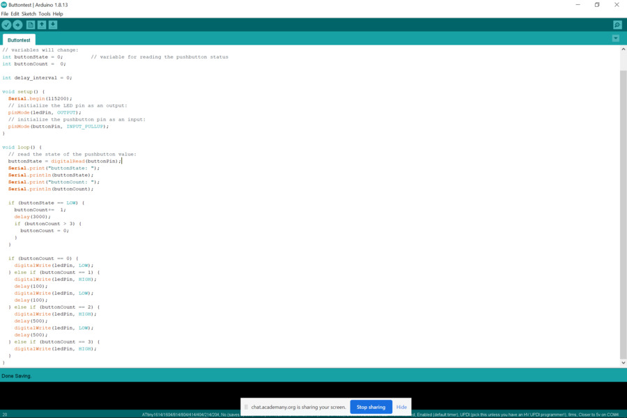
6.Try LED program.
  const int buttonPin = 3;     // the number of the pushbutton pin
  const int ledPin1 =  0;      // the number of the LED pin
  const int ledPin2 =  1;      // the number of the LED pin
  const int ledPin3 =  6;      // the number of the LED pin


  // variables will change:
  int buttonState = 0;         // variable for reading the pushbutton status
  int buttonCount =  0;

  int delay_interval = 0;

  void setup() {
    Serial.begin(115200);
    // initialize the LED pin as an output:
    pinMode(ledPin1, OUTPUT);
    // initialize the pushbutton pin as an input:
    pinMode(ledPin2, OUTPUT);
    // initialize the pushbutton pin as an input:
    pinMode(ledPin3, OUTPUT);
    // initialize the pushbutton pin as an input:
    pinMode(buttonPin, INPUT_PULLUP);
  }

  void loop() {
    // read the state of the pushbutton value:
    buttonState = digitalRead(buttonPin);
    Serial.print("buttonState: ");
    Serial.println(buttonState);
    Serial.print("buttonCount: ");
    Serial.println(buttonCount);

    if (buttonState == LOW) {
      buttonCount+=  1;
      delay(3000);
      if (buttonCount > 3) {
        buttonCount = 0;
      }
    }

    if (buttonCount == 0) {
      digitalWrite(ledPin1, LOW);
      digitalWrite(ledPin2, LOW);
      digitalWrite(ledPin3, LOW);
    } else if (buttonCount == 1) {
      digitalWrite(ledPin1, HIGH);
      delay(100);
      digitalWrite(ledPin1, LOW);
      delay(100);
    } else if (buttonCount == 2) {
      digitalWrite(ledPin2, HIGH);
      delay(500);
      digitalWrite(ledPin2, LOW);
      delay(500);
    } else if (buttonCount == 3) {
      digitalWrite(ledPin3, HIGH);
    }
  }
I added three LED lights on my board so I had to check if all of them work right.
With many helps by my instructor I wrote program like the below.
Hero Shots
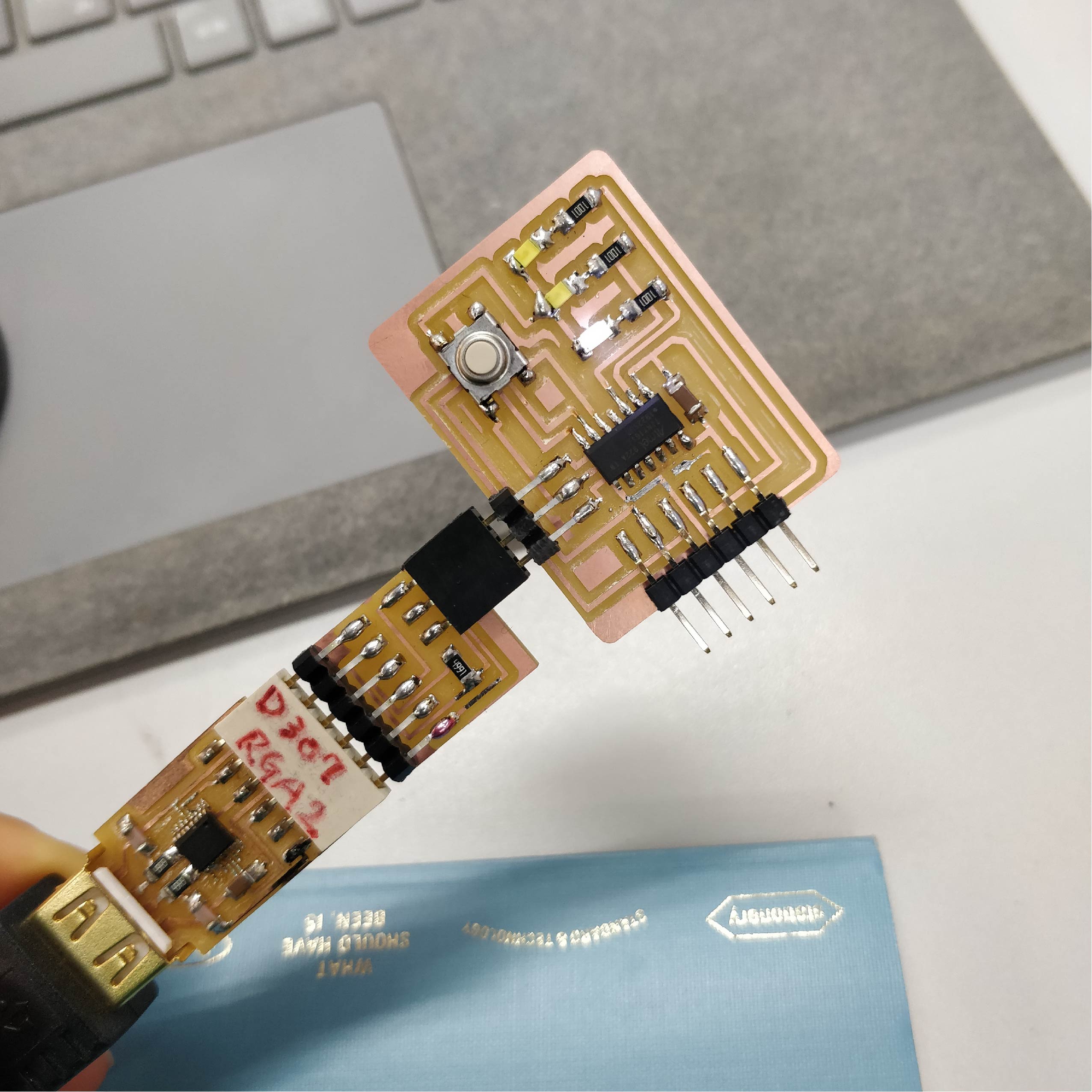
Thoughts
The Connections between PC and the boards are very important. If it doen't work right, I should check connections several time.(I did it for this time but my in circuit programmber didn't work untill the end...)
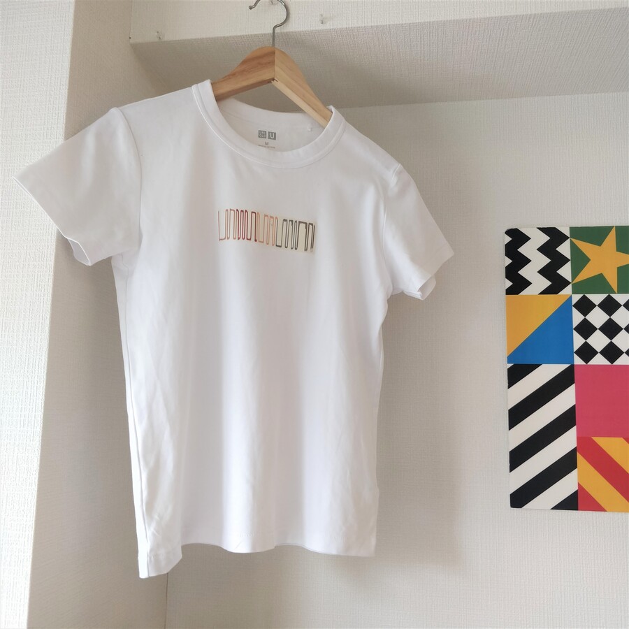
Spin-Off...Just for Fun!
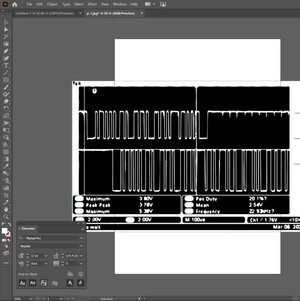
Through the group assignmen I used oscilloscope. I was impressed with amazed by binary concepts and the waveform shape on the monitor which I can read the letters from it. It was like cryptography and I felt like I can use this misterious waveform for texitle design to tell somebody hidden message…!
So I created this "Binary Hello T-shirts "in spare time.
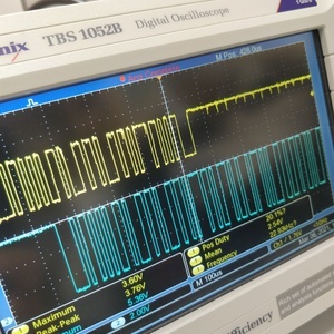
The waveform on the monitor of oscilloscope when I typed "hello".
Trace screenshot with Adobe Illustorator.
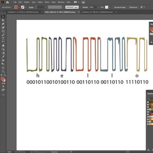
Check which part each letter is. Then separate shape to each letter by coloring .
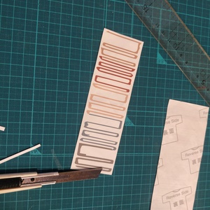
Print on Inkjet Iron On Transfers Paper. Cut it.
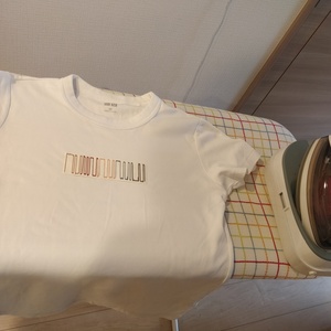
Transfer image to T-shirt by ironing.

DONE!
Files
PNG FILE(top_1614LED.png)
PNG FILE(outline_1614LED.png)
EAGLE FILES(Hello1614_LED.zip)