WEEK 8 Embedded Programming
Group Assignment
compare the performance and development workflows for other architectures
This week’s group Assignment is written in here
Individual Assignment
read a microcontroller data sheet
program your board to do something,
with as many different programming languages and programming environments as possible
Reading Data Sheet
Myboard was ATTINY1614, so I downloaded the datasheet from here
From the datasheet I could learn such as….
1.“ATTINY 1614” means… (page.1)
- 16KB-flash
- 1-series
- 4(14pins)
2.Pinout (page.14)
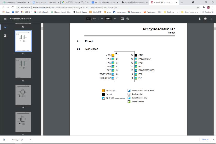
3.Pinname (page.14)
Pin names are of type Pxn, with x being the PORT instance (A, B) and n the pin number. The notation for signals is PORTx_PINn. All pins can be used as event input.
Ex.PA0 means
- PORTA
- Pin number 0
Debugging My In-circuit Programmer
Problem1 In-circuit Programmer
On week6, I made my in circuit programmer but it didn’t work, so I had to fix the problem at first. I tried the new microscope which my instructor got to find out the error part on my board. As I magnified my in-circuit programmer with it, I could tell that some part of FT230XS was not touched to lead. So I resoldered it then it worked!
What I found convenient was that I could take the screenshot on the microscope.
The following are the screenshots of BEFORE/AFTER resoldering.
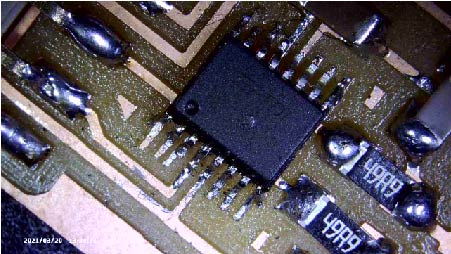
Before
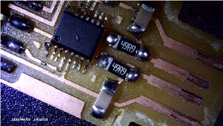
After
Programming My board
I was very happy to move on to programming with my own in-circuit programmer.
TIPS
There are useful tips to make understanding easier.
To comment out the specific lines , use the code below.
(1)if it's single line
Add // before the line.
(2)if they are multiple lines
add /* before the first line
and add */ after the last line
Environment Settings
1.Add Boards Manager URLs http://drazzy.com/package_drazzy.com_index.json from File>Preferences>"Additional Board Managers URLs" text box \ in Arduino.
2.Add “build.path=C:\Users\natsu\Documents\Arduino\build” in preference.txt
3.Select “megaTinyCore” from Tool>board>Board manager
4.select appropriate COM port from Tool>Port
Programming Environment 1.pyupdi
For the first program environment, I tried pyupdi.
$ cd ~/Documents/Arduino/build
$ ls
Buttontest.ino.hex
$ pyupdi -d tiny1614 -c COM4 -b 57600 -f Buttontest.ino.hex
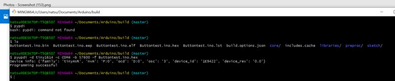
For Buttontest.ino.hex, I used the program that my instructor Homma-san made in the past.
Programming Environment 2.Arduino IDE (megaTinycore2.2.9)
Second, I tried Arduino IDE megaTinycore2.2.9.
The procedures were as follows.
1.Install megaTinycore version 2.2.9
1-1.Select Tools > Boards > Board Manager
1-2.On board manager window, search for"megaTinycore", then select "2.2.9"from version pull down.
1-3.Push "Update"
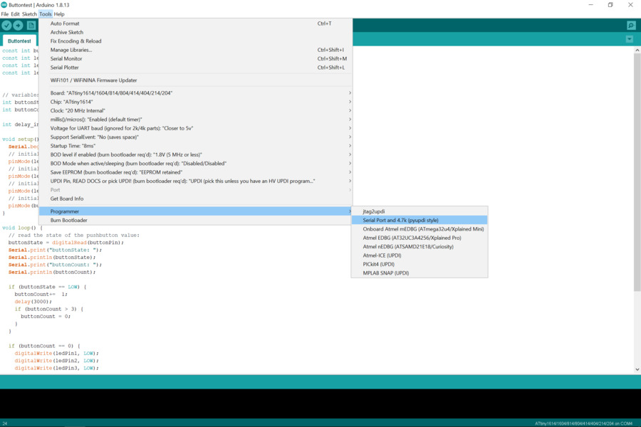
2.Chose Tools>Programmer>Serial Port and 4.7k(pypi style)
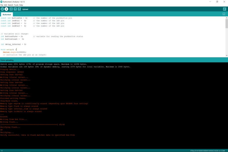
I added three LEDs on my board, so programmed to make all the LEDs shading depending on the times to push the buttons.
I could get the same results from two types of programming environment.
Programming Language 1.Arduino
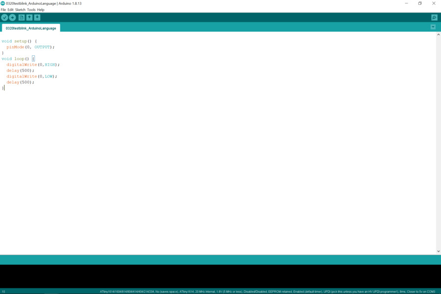
First programming language I tried was Arduino Language.
Test1: To make only one LED blinking.
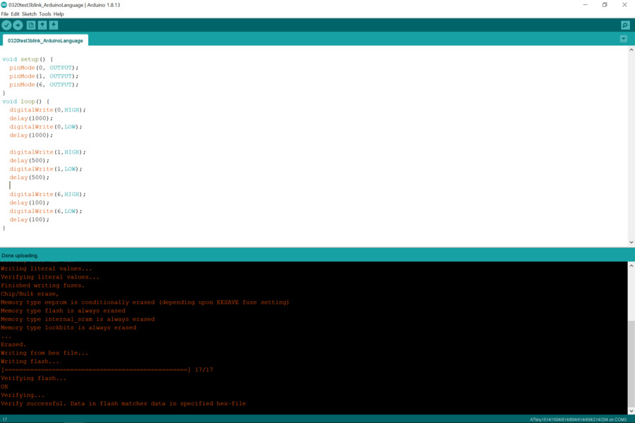
Test2: To make all three LEDs blinking in order.
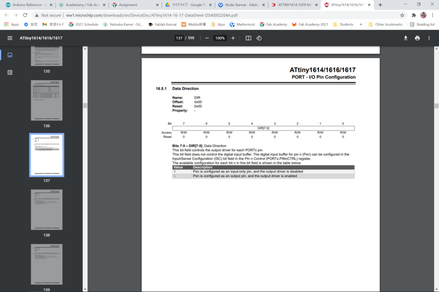
Programming Language 2.Operating from register
In this way, I needed to use binary, so I checked the page 137 “16.5.1 Data Direction”of the datasheet to convert pin number to binary from decimal.
Test1: To make only one LED blinking.
problem 2 code error
I wrote like the below firstly and it didn’t work.
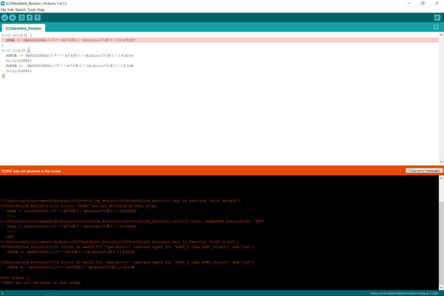
so I checked the datasheet and refer to “16.5.1 Data Direction”
Then I rewrote my code like this.
void setup() {
PORTA.DIR |= 0b00010000;//portA 4 pin(Arduino 0 pin)is OUTPUT
}
void loop() {
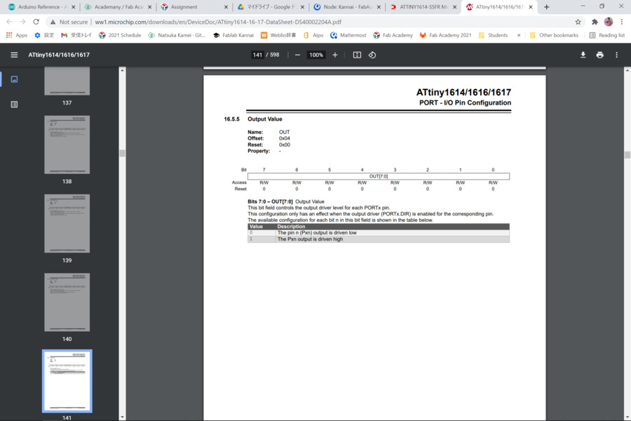
PORTA.OUT |= 0b00010000;//portA 4 pin(Arduino 0 pin)is HIGH
delay(1000);
PORTA.OUT &= ~0b00010000;//portA 4 pin(Arduino 0 pin)is LOW
delay(1000);
}
Test2: To make all three LEDs blinking in order.
  void setup() {
    PORTA.DIR |= 0b00110000;//portA 4 pin(Arduino 0 pin)is OUTPUT
    PORTB.DIR |= 0b00000010;//portB 1 pin(Arduino 6 pin)is OUTPUT
  }
  void loop() {
    PORTA.OUT |= 0b00010000;//portA 4 pin(Arduino 0 pin)is HIGH
    delay(1000);
    PORTA.OUT &= ~0b00010000;//portA 4 pin(Arduino 0 pin)is LOW
    delay(1000);

    PORTA.OUT |= 0b00100000;//portA 5 pin(Arduino 1 pin)is HIGH
    delay(500);
    PORTA.OUT &= ~0b00100000;//portA 5 pin(Arduino 1 pin)is LOW
    delay(500);

    PORTB.OUT |= 0b00000010;//portB 1 pin(Arduino 6 pin)is HIGH
    delay(100);
    PORTB.OUT &= ~0b00000010;//portB 1 pin(Arduino 6 pin)is LOW
    delay(100);
  }
Results
I could get the same results from two types of programming Languages.
Test1
Test2
Thoughts
Microscope made debugging much easier and it was fun to use!
If I know the way to write code by operating a register, I can make my program shorter and more efficient to speed up the processing time.
Files
0320Buttonfading.ino
0320Buttontest.ino
0320test3blink_ArduinoLanguage.ino
0320test3blink_Register.ino
0320testblink_ArduinoLanguage.ino
0320testblink_Register.ino