The following is information of the Lasercutter used at Fablab Kannai.
 Universal VLS 2.3
- Work area is 406x305x102mm(16"x12"x4")
- 30W CO2
Focus
A lense of our laser cutter was 2.0” (25.4 x2 = 50.8mm).We chose 3.0 mm plywood for our experiment, so jig on the table at the beginning was z=3.0mm.
We tried to cut the vector line by changing the focus by up/down key from +1.2 to -0.7 by 0.1mm
.jpg)
surprisingly we couldn't find much difference by changes of 0.1mm.
.jpg)
Next we changed forcuses by every 0.5 mm then the differences got more obvious!
Power,Speed,Rate
The best setting for 3mm cardboard was Power80%,Speed10%,Rate250PPI
We used this file for the test.First we checked the best power and speed with the changes of the parameters by every color.
 SVG file
From the result of last year, we knew that we can cut with 50% power and 4% speed. If we speed up to 10%, we needed 80% power but still we could cut nicely.
Second we investigated the rate by fixed speed. 250 pp was enough for 3mm cardboard.
Kerf
Kerf for our machine is 0.16mm
The left image is the data to clearfy the kerf for our lasercutter .
To reduce errors when measuring with calipers, we tried to find the 9 times value of actual kerf by mesuring 9 sticks.
90mm(width on the data)-88.5mm(width measured with caluper)=15mm
15mm/9(the number of sticks)=0.1666...(kerf)
Joint clearance
0.1mm joint clearance is the best for our machine to cut 3mm cardboard.
With this data, we made the joint for the clearance test.Before we set the para, needed to measure the actual thickness of cardboard and it was 2.78mm.
For the parameters, we set the following.
t3(thickness):2.78mm
kerf:0.16mm
pitch(joint clearance):0.1mm
len30(hights):30mm
w5(width of each sticks):5mm
For each sticks, we gave different joint clearance by 0.1mm then, found out that 0.1mm joint clearance is the best fit for 3mm cardboard.
Also I figured out 2.58mm is the best width for the slit for my construction kit.
2.78mm(actual thickness of cardboard)-0.16mm(kerf)-0.1mm(joint clearance)=2.58mm
Files for Group Assignment
- Focus test file
svg
cdr
- Power-Speed-Rate test file
svg
cdr
- Kerf test file
stl
f3d
- Joint clearance test file
stl
f3d
Individual Assignment 1 Construction Kit
design, lasercut, and document a parametric construction kit, accounting for the lasercutter kerf, which can be assembled in multiple ways,
and for extra credit include elements that aren’t flat
My Idea
I got inspiration for my construction kit from the shape of tree.Trees are an example of a natural fractal object ...because each branch is repeated by using the original shape of the trunk and each time is rotated and down-sized. I was amazed that the nature has not only right-brained beauty but also left-brained beauty.
ref:Fractal Tree
Make mock-up
For my construction kit I wanted to mix some ramdomness into geometric design. So I decided to add some little flowes and leaves to my fractal tree.
Before I start designing with softwares, I needed to test how it looks like. But it was late night and I didn't have nice material for my mock-up...
.jpg)
Finally I
used styrofoam from fish tray to make my mock-up..!
(I just made my prototype by hands with scissors to check the construction.
Styrofoam is not suitable material for my laser cutter.)
.jpg)
It was not fancy but played a role.
Design(Vector)
Next I made data with Adobe Illustrator and convert the AI file to dxf data for parametric design with fusion 360..
My instructor told me that the image size might change when importing dxf file to fusion 360. So I made the test file and check how it goes.
(There wasn't any change this time with illustrator 2020,however it might differ by the version)
Design(parametric)
I got confused by operation of fusion 360 due to my inexperienced skills and got many many help by my instructors.
In the parametric data,I used the kerf and joint clearance which I found out in the group assignment.
Kerf for our machine was 0.16mm and joint clearance was 2.58mm.

Lasercut and Assembly
Next one was fun part!Laser cutting.
I tried to use Deepnest but after I installed it my computer freezed....I'll try it again another time.
.jpg)
The followings are procedures we should follow to use our laser cutter.
1.Settings on CorelDRAW
We use CorelDRAW on our computer connected to the laser cutter.
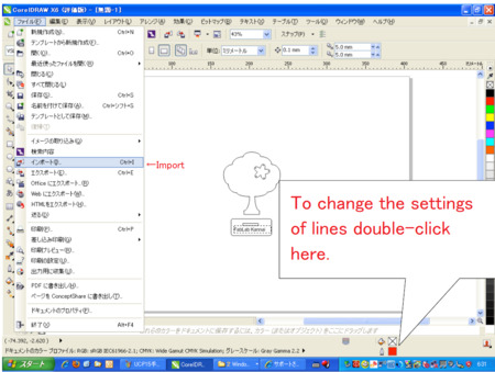
1-1.Save the file as illustrator CS if you use Adove illstrator of newer version than CS.
1-2.Import it into CorelDRAW from “File”Tab >”Import”.
1-3.Change the settings of drawing lines from the bottom of the screen as follows.
1-4. Print it to “Universal Control Panel”
Line width :Hairline
Line color : Red (255,0,0)
2.Settings on Universal Contorl Panel
Universal Control Panel is where we can change the settings for the laser cutter.
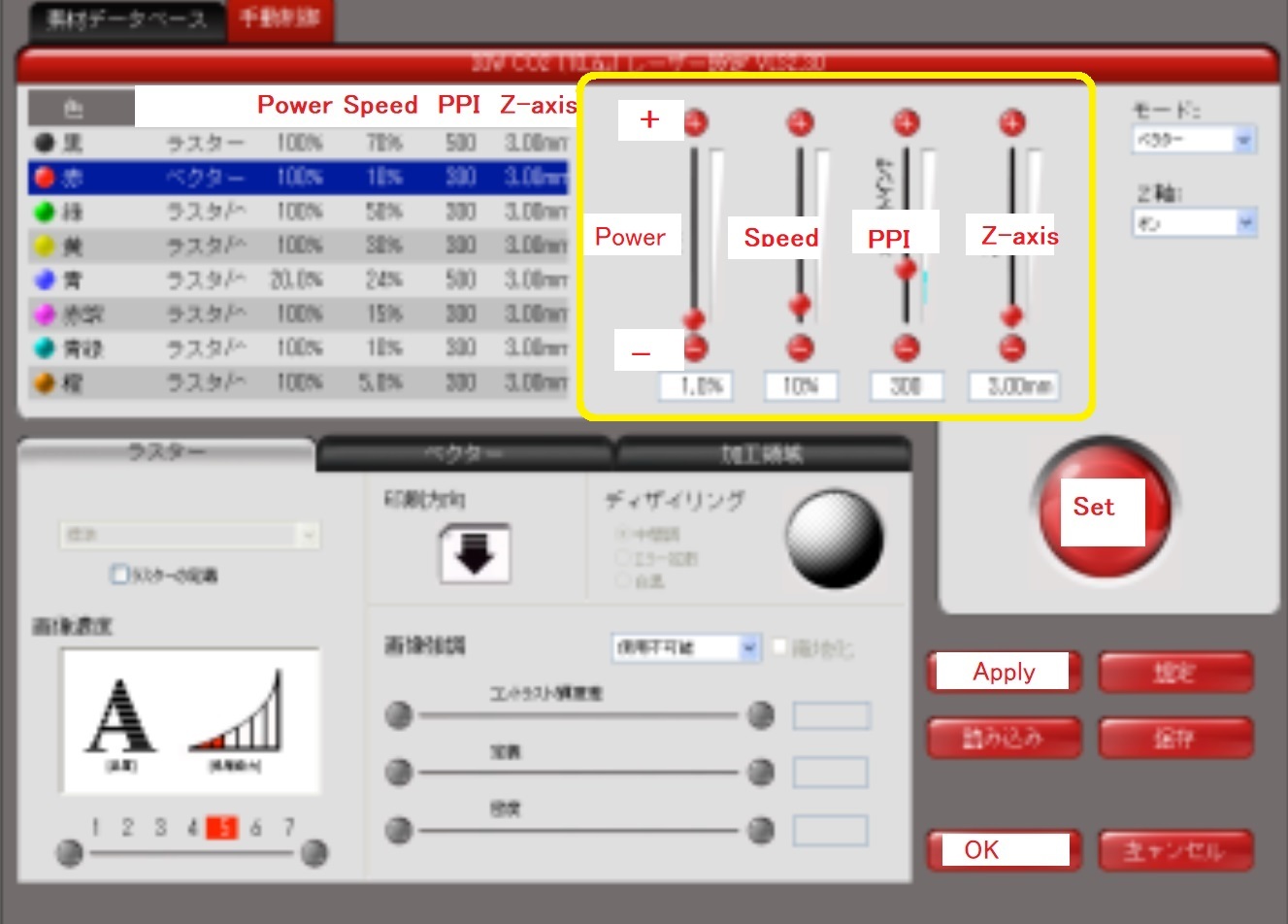
2-1. Change the parameter from the part boxed with the yellow line on the screenshot. Then press "Set">"Apply">"OK".
This time I used the parameter I found out through the group assignment.
In group assignment, we did the test to find out the best parameter for 3mm cardboard. we I tried various power,speed, and PPI and learned that the best parameter for 3mm cardboard was Power 80%,Speed 10%,Rate 250PPI.
So I used this results to lasercut my construction kit and it worked well.
.jpg)
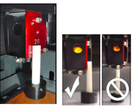
2-2.Set the forcus.By clicking the “Focus Point”botton on the screen, move the pointer of the laser cutter on the materials.
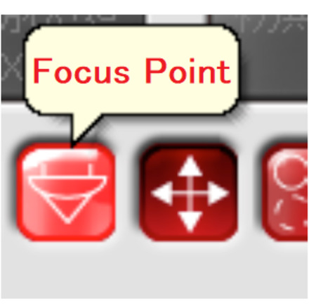
With the forcus tool in the image below and the UP/DOWN key of the laser cutter, adjust the focus.Don’t set the focus tool under the pointer like the image on the right.
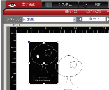
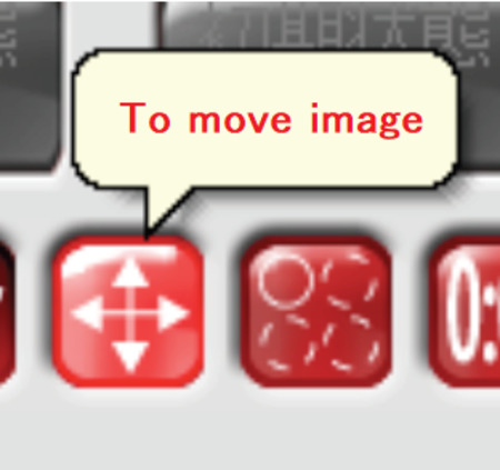
2-3. Move the image to the right place from the “Move the image”button on the screen.
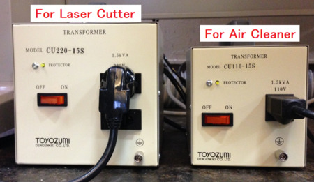
3. Turn on the systems
After all settings on the computer, now turn on the switches of the systems.
One is a power transformer for the laser cutter, and another one is for the air cleaner.
Since those systems make big sounds, don’t forget to turn off them once you finish laser-cutting.
4.Finally start cutting by the “▶”button on the screen!
.jpg)
Cutting...
.jpg)
Some mistakes in right bottom part.
.jpg)
my hands got dirty by soot of cardboard...
Assemble
Thanks to many test in group assignment(to figure out the best parameter,kerf,and joint clearance), my construction kit fitted well.
One thing I would like to change next time was the design of the slit. The length of the slit was a bit too short so fitness was weak.
My hero shots

(Behind the hero shots...😛)
.jpg)
Fablab Kannai has a little photoshoot studio!
.jpg)
Serious moment...
.jpg)
With today's hero,Universal VLS 2.3!
Individual Assignment2 Vinyl Cutting
cut something on the vinylcutter
My Idea
For this time my inspiration comes from this masterpiece of Banksy.

Design
I took picture of me in the my cellphone and trace it through Adobe Capture CC. Then I made this vector image of silhouette.

Cut
This was the first time for me to use vinyl cutter. Our vinyl cutter was Silhouette CAMEO
.jpg)
The followings are the procedures I followed to use it.
1.Install Silhouette Studio which is the software for the Silhouette CAMEO.
2.Export my vector data into a DXF file. on the Adove Illustrator.
3.Import it into Silhouette Studio.
4.Adjust size or alignment of data for cutting in design view of Silhouette Studio.
5.Set the parameter as follows from clicking on “SEND” button on the top of the screen.

Materials : Cutting Film Gross
Action : Cut
Tool :Ratchet blade
Cutting pressure :4( Don’t forget to change it from the both of setting on the software and adjuste dial of the machine)
Force :10
Path :1
6.Then cut!
I was worried about small parts in my design, but in spite of my worry the first cut went smoothly and had no trouble!I was surprised it was much smaller and quietter than laser cutter...
Sand blast
Luckily I got chance to experience sand blast!This was the most exciting moment of this day.
.jpg)
Covering with masking tape.
.jpg)
Inside of the sandblast machine.
.jpg)
Another serious moment....
My hero shots
There is tiny gimmick for this glass cup...only if you use this as flower base...


.jpg)
Shine the p>light on the glass with flowers inside ....then..

Shadows will apear on the wall:)
Files
-Construction kit 2D design file
dxf
ai
-Construction kit parametric design file
stl
f3d
-Construction kit laser cutting file
svg1
svg2
ai1
ai2
-Vinyl Cutting design file
svg
ai
DXF