WEEK14 Networking and Communications
Group Assignment
send a message between two projects
Individual Assignment
design, build, and connect wired or wireless node(s)
Basic Info
I2C
From the classI learned many kinds of networking and communcations, but this time we chose to try I2C.
For I2C communications, we need to decide Masterand Secomdary first.
SDL (Serial Clock) SCL(Serial Data), VCC ,GND are necessary pins to connect for the communication.
10kΩ pull-up resisters for SCL and SDA are assembled inside of OLED, so even my ATTiny 3216 board has no pull up resistor, OLED by I2C worked normally.
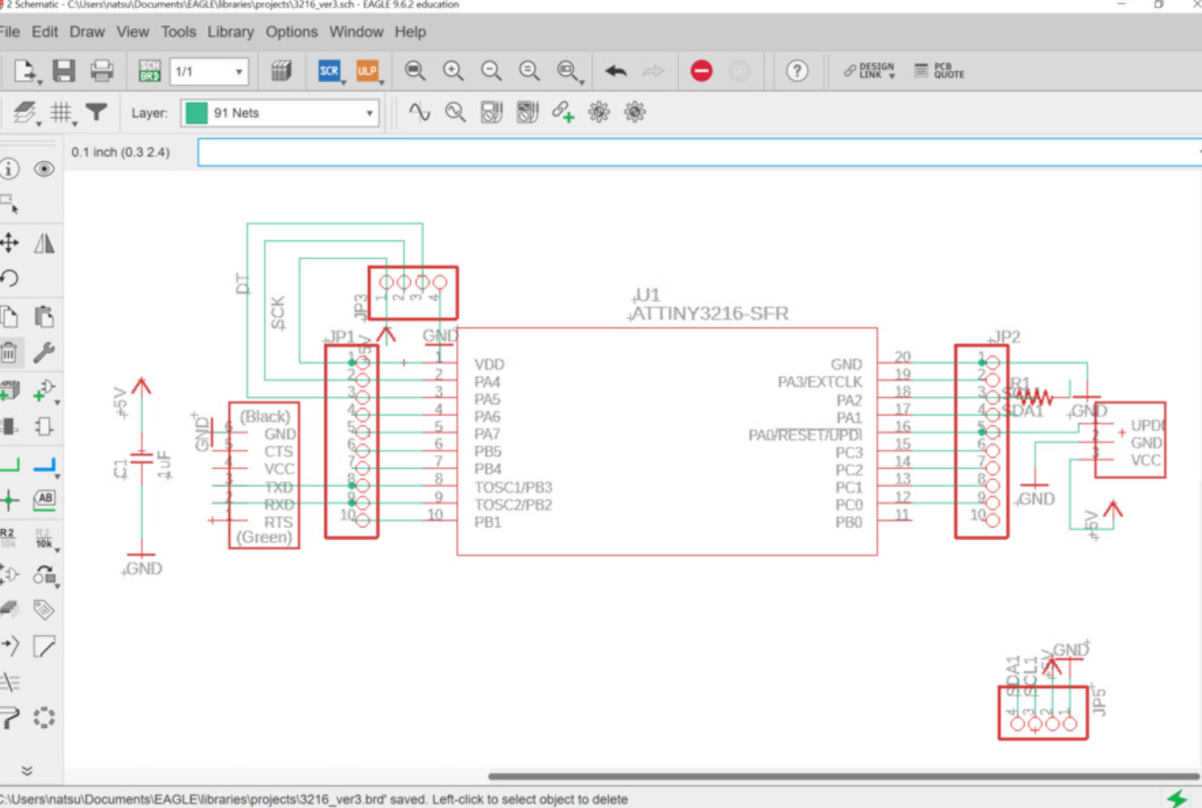
I decided to use ATtiny3216 breakout board I have made before for master, and OLED for Secondary this time.
Device
128x64 OLED (Ref:Amazon)
- Size: 0.96 inc
- Resolution: 128 x 64
- Color: Blue & Yellow
- Visible angle: 160 degrees or more
- Support platforms: arduino 51 series, MSP430 series, STM32/2, CSR chip, etc.
- Ultra low efficiency consumption: normal 0.04 W.
- Wide voltage support: DC 3.3V-5V
- Drive Chip: SSD1306
- Communication Method: IIC, I/O ports only 2
- No font: take software word
In the local session,we followed the instructions which my instructor made.
1.Install NecessaryLlibralies
My client environment was Arduino IDE 1.8.10.
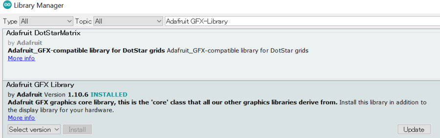
I installed the following two libraries from Arduino IDE > Tool > Manage Libraries…
Adafruit SSD1306 ver. 2.4.4
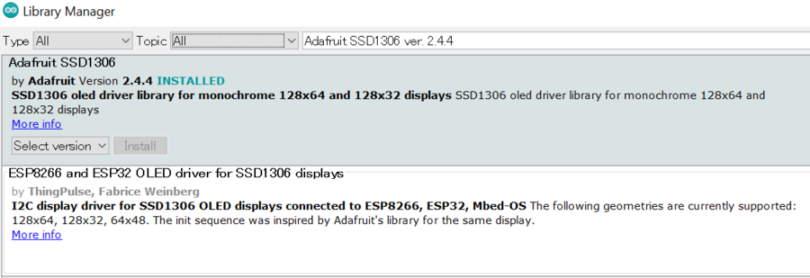 Adafruit GFX-Library ver. 1.10.7
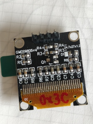
2.Check I2C addres from the back of the OLED
My OLED was the type that doesn’t have the position of 0Ω resister on the back of the display.
If it has, I can check and adjust I2C address by the position of 0Ω resister.
My address was 0x3C
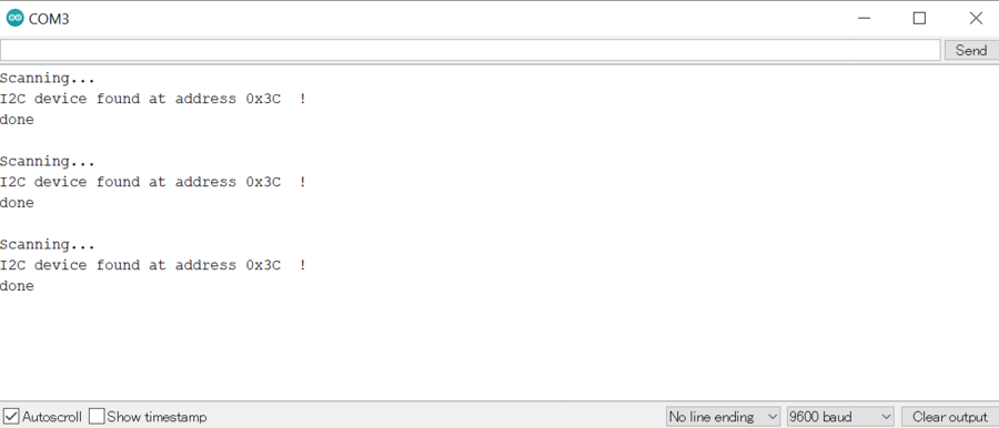
3. Get the I2C communication working.
The sketch below scanned the I2C-bus for devices. On the serial monitor, my device was found.
05012C_Adress_Scanner.ino
4.Connect the pins
Watching out for the the order of the pins , I connected the pins as follows.
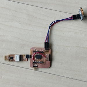
From the top, GRN(red),VDD(blue),SCK(red),SDL(blue)
5.Progmramming
5-1.Select the Sample Program
Arduino IDE > File > Examples > Adafruit SSD 1306 > ssd1306_128x64_i2c
5-2.Change the line arround line no:35
Before
#define SCREEN_ADDRESS 0x3D
After
#define SCREEN_ADDRESS 0x3C
5-3.Switch SCL/SDA pins
ATTiny 3216 has two kinds of SCL/SDA pins.
Looking back Week11 Input Devices,
I used SCL1/(PA2) SDA1(PA1) for OLED pins.
By adding the code below, I could switch SCL/SDApins to SCL1/SDA1 pins.
Wire.swap(1)
Entire code was as follows:
0501OLED.ino
5-4.Write the program by UPDI
Then write program by “Upload” function.
Before it I needed to check if my setting was right as follows:
- Arduino IDE > Tool
- Board: ATtiny3216
- Port:COM3
- Programmer: “Serial Port and 4.7k(pyupdi style)”
5-5.Results
It worked!!
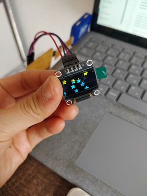
Just for Fun…
Since I’m thinking of using an OLED for my project Automatic Sake pouring Machine, I played with some proggram to show the message….
I haven’t decided the details of the way I use OLED...
0501OLED_youaredrunk.ino
Thoughts
At first I didn't understand the difference between I2C communitcations and the connecting the boards by the wires.I asked questions to my instrutor and they explained the relations of master and secondary.It made sense to me, now I realized the possibility of the networking and communications well.
I have not had ideas with it for my final project yet, but looking forward to make use of it in the future.
Files
05012C_Adress_Scanner.ino
0501OLED.ino
0501OLED_youaredrunk.ino