Weekly Summary
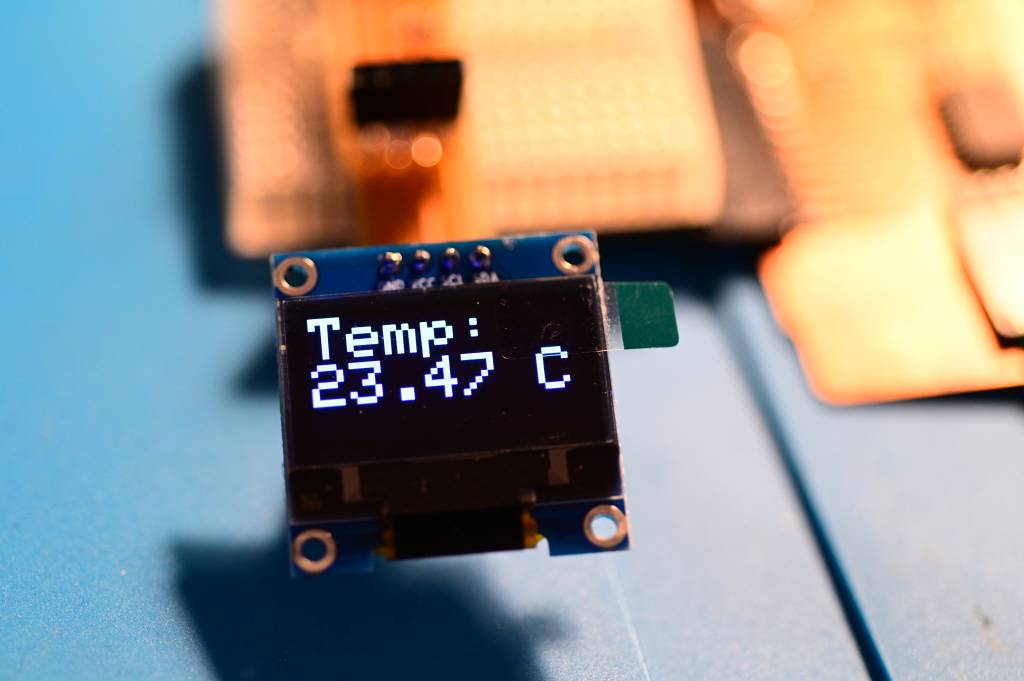
For this week's Output Devices I compared a range of Peltier Devices, and made a I2C break-out board for my 3216 board. I had some troubles getting one OLED to work, but after I got another one, the graphic output and temperature display worked.
Group Assignment
This week's group assignment is to measure the power consumption of output devices.
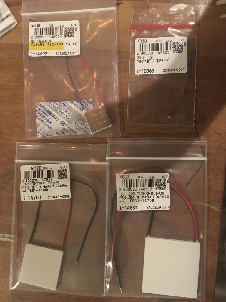
My Final Project will involve heating and cooling, therefore I got a range of Peltier Devices, this group assignment is to find out the power consumption of these different-sized Peltier Devices.
More details on the Output Devices Group Assignment Page.
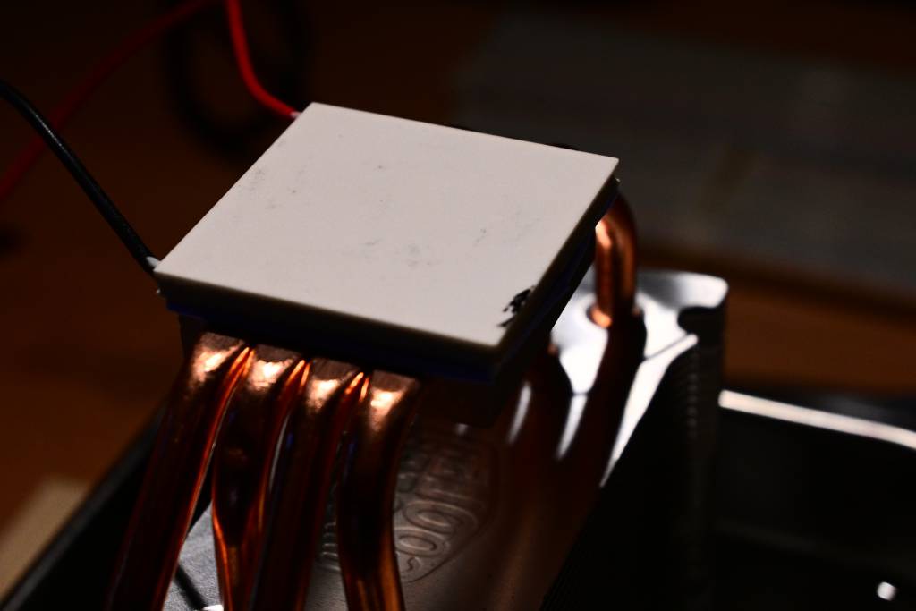
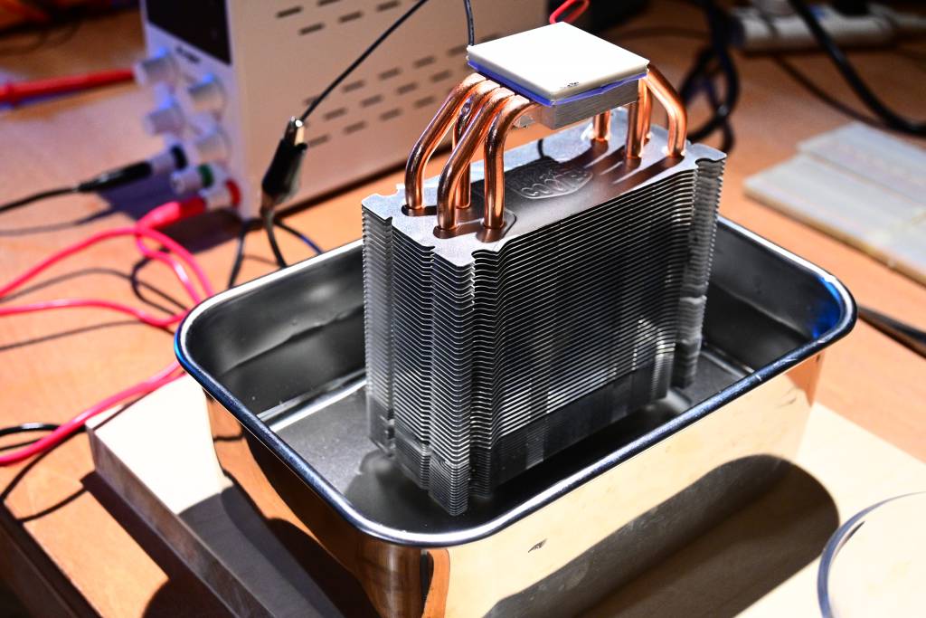
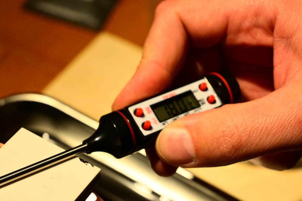
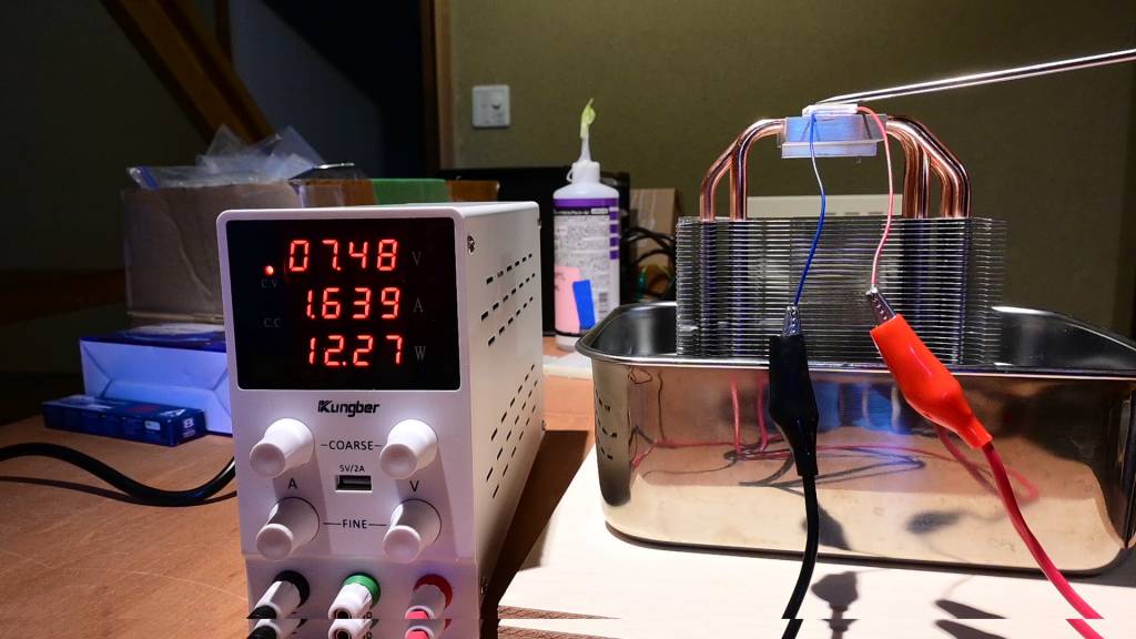
Because Peltier Devices can get really hot, we mounted them on a cooling rig, fixed them with heat-conductive tape - and submerged the cooling rig into water to dissipate the heat.
- P is the power measured in watts
- V is the voltage measured across the conductor in volts
- I is the current measured in Ampere
The relationships between P, V, I and R is shown in detail in the an Ohm's Law Pie Chart.

How to measure the Power?
We have a Kungber Stabilized DC Power Supply at Fablab Kamakura, which can be used to set max values for both Voltage and Ampere, and allows you to observe the power consumption. The Kungber Power Supply has 2 controls for each V and I, allow for coarse and fine control.
The Peltier Device Lineup:
| Name | Size (mm) | Vmax | Imax | Max Δ Temp (ºC) | Links |
|---|---|---|---|---|---|
| TEC1-12708 | 40 x 40 | 15.4V | 8.5A | 66 | Get, Datasheet |
| TEC1-12739 | 30 x 30 | 16.0V | 4.6A | 70 | Get, Datasheet |
| TEC-40865A-00 | 17 x 17 | 8.2V | 2.1A | 67 | Get, Datasheet |
| Melcore-CP1.0-1-05 | 3.5 x 3.35 | 0.12V | 3.9A | 67 | Get, Datasheet |
Decoding Peltier Devices
- TEC1-12708: stands for Thermo-Electric
- TEC1-12708: Either C or S. S for Smaller
- TEC1-12708: Number of Stages, in this case: 1
- TEC1-12708: Number of Thermocouples: 127
- TEC1-12708: Max Ampere Rating: 8
It seems Peltier Devices do not always following this convention.
TEC1-12708
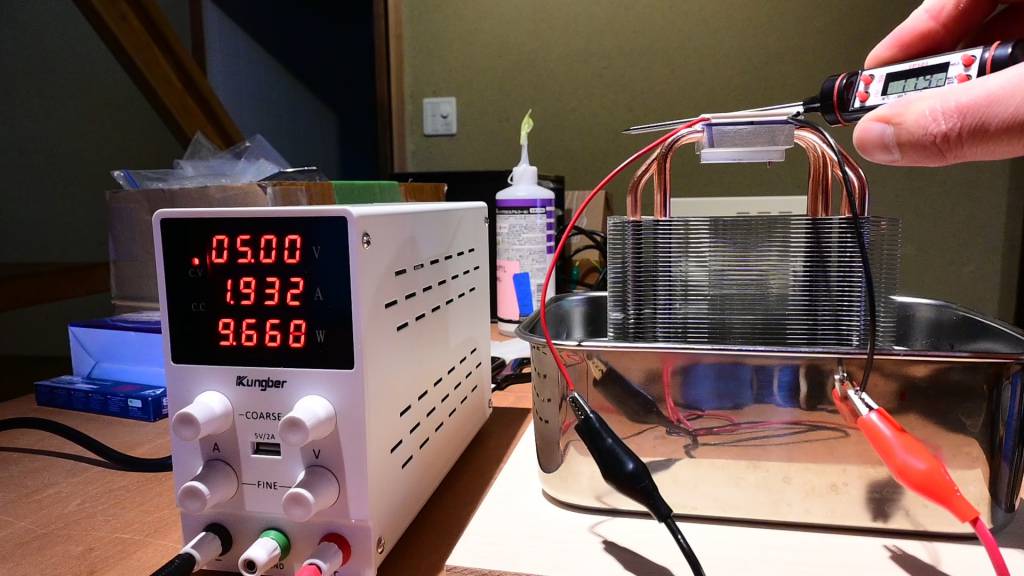
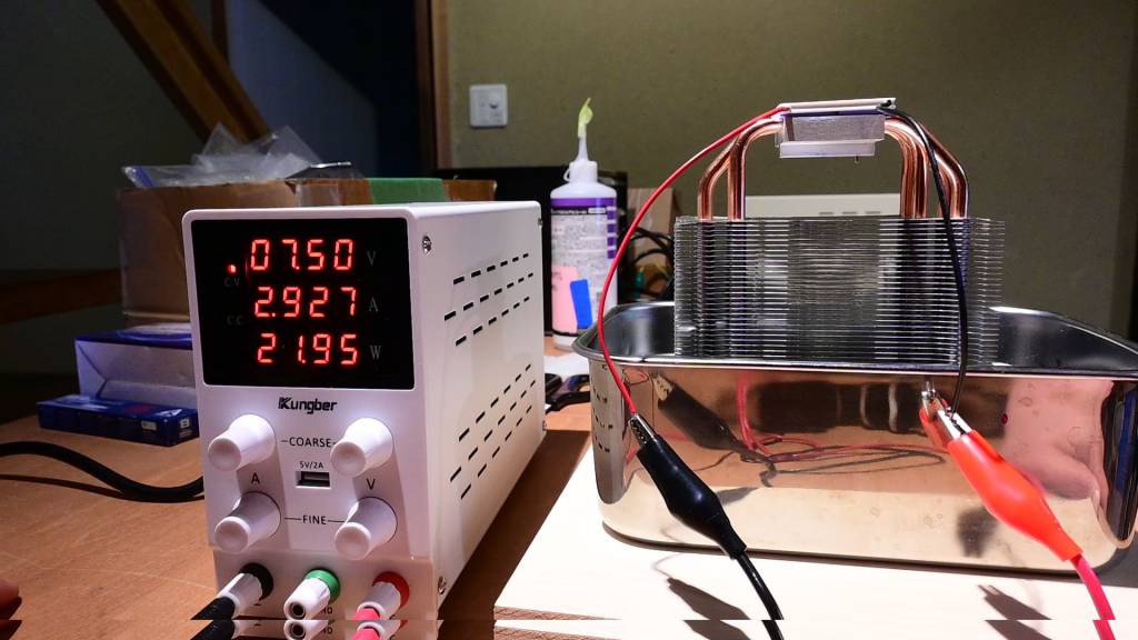
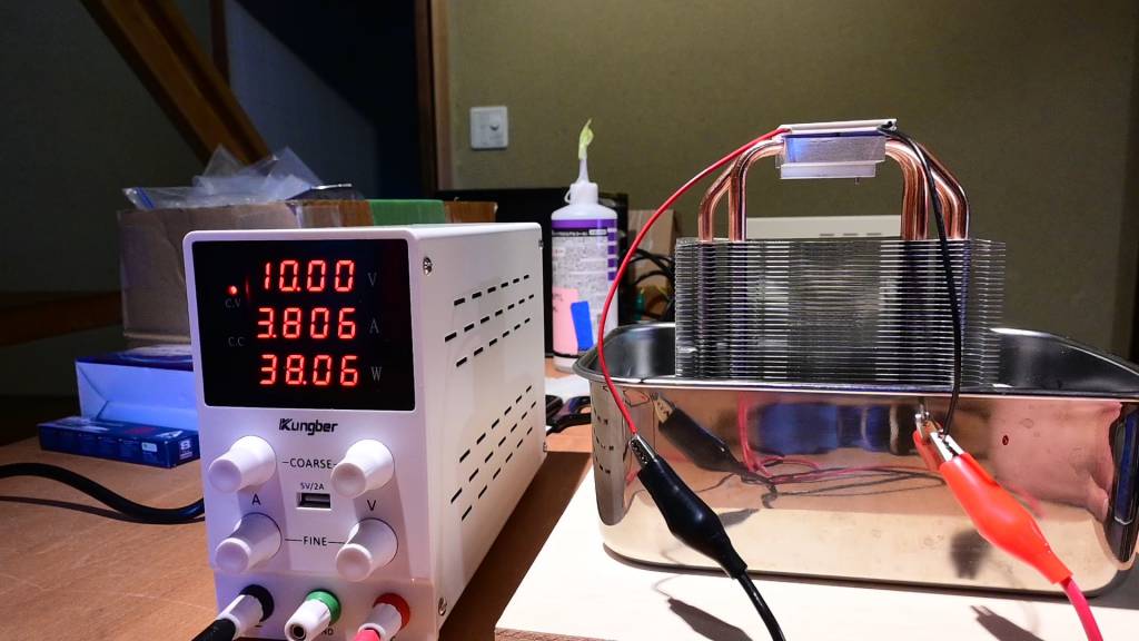
| P | V | I |
|---|---|---|
| 9.66 | 5 | 1.932 |
| 21.95 | 7.5 | 2.927 |
| 38.06 | 10 | 3.806 |
TEC1-12739
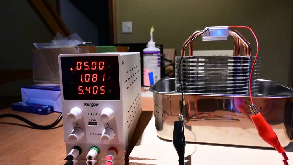
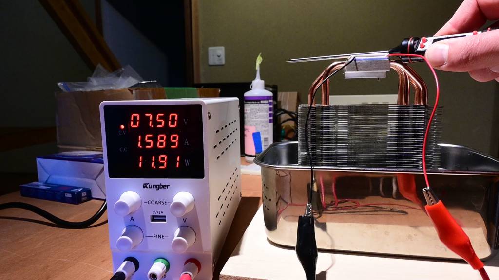
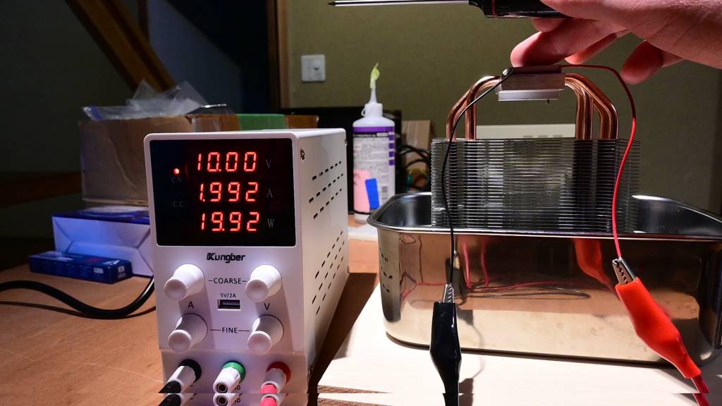
| P | V | I |
|---|---|---|
| 5.405 | 5 | 1.081 |
| 11.91 | 7.5 | 1.589 |
| 19.92 | 10 | 1.992 |
TEC-40865A
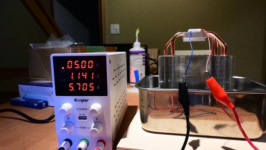
| P | V | I |
|---|---|---|
| 5.705 | 5 | 1.141 |
| 12.27 | 7.48 | 1.639 |
As the max Voltage for this device is 8V, I did not test at 10V.
Melcore-CP1.0-1-05
The Melcore-CP1.0-1-05 has a max voltage of 0.120V or 120mV, it was not possible to test it with this setup, as the power supply could not create a stable output at 120mV.
TODO: Find other ways to measure the power consumption.
Performance
We observed that the more voltage we applied the more the Peltier device cooled. At some point the hot side overwhelmed the cool side and started heated the cool side as well, resulting in a temperature rise of the cool side.
If higher or cooler temperature are necessary, Peltier devices can be stacked.
Further experiments regarding the correct cooling parameter are necessary.
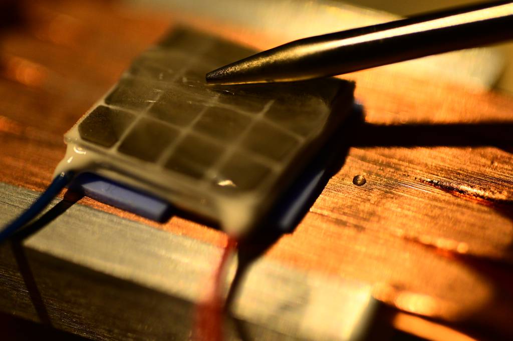
Ice!
We also managed to make (a small amount of) ice!
Reverse Peltier: The Seebeck Effect
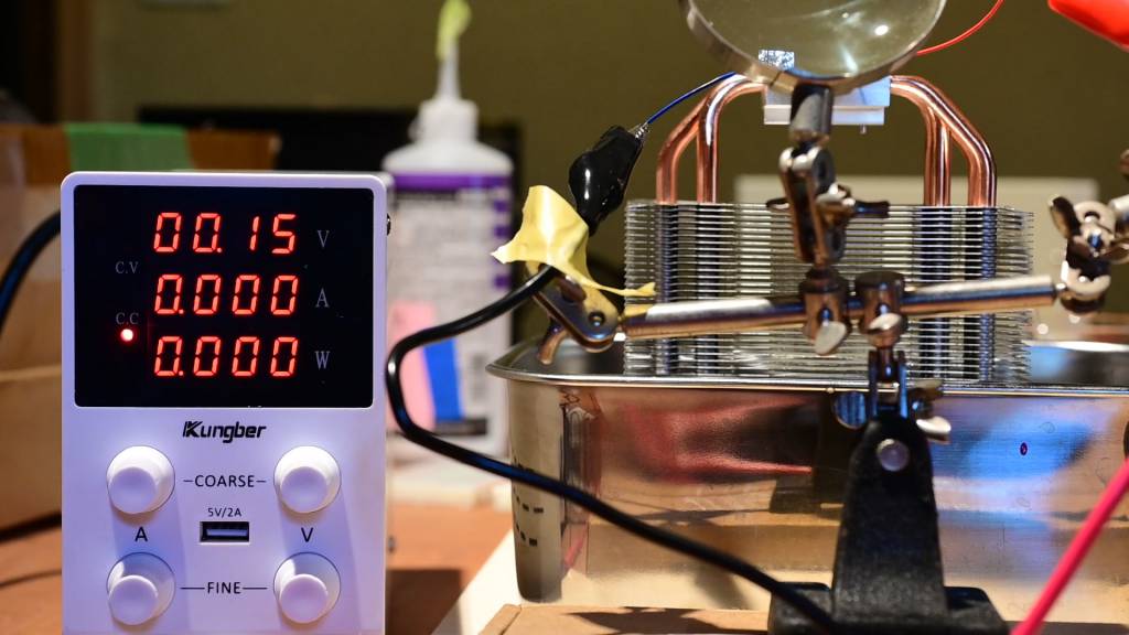
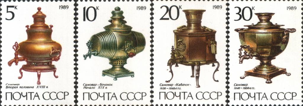
After turning the V and I down, we could observe that the still hold/cold Peltier device was creating electricity. This is the thermoelectric effect or Seebeck-Effect</span, which apparently was discovered (or re-discovered) by Thomas Johann Seebeck in 1821. Seebeck was a Baltic German, which fits into the story I was once told, that Samovars (самовар, "self-brewer", metal container to boil and keep hot water, mainly used in Russia) have been used to generate electricity. Makes sense... If someone has more details, please do let me know.
Individual Assignment
Assignment Work Plan
My assignment plan for this week is:
- Test the Peltier Devices (which I got from my recent trip to Akihabara) ✅
- Make an extension board for my 3216 to allow for the OLED I2C connection - and the temperature sensor. ✅
- Write code to to display temperature data on the OLED ✅
- Investigate how exactly Peltier Devices want to be driven, the candidates so far: ON/OFF, PWM, PWM + Low Pass. ✅
- Make a board with temperature sensors, OLED and Peltier.
I am planning to design the board on Friday, mill, make and stuff it on Saturday during the FabLab Kamakura Lab Session and write & test the code on Sunday/Monday.
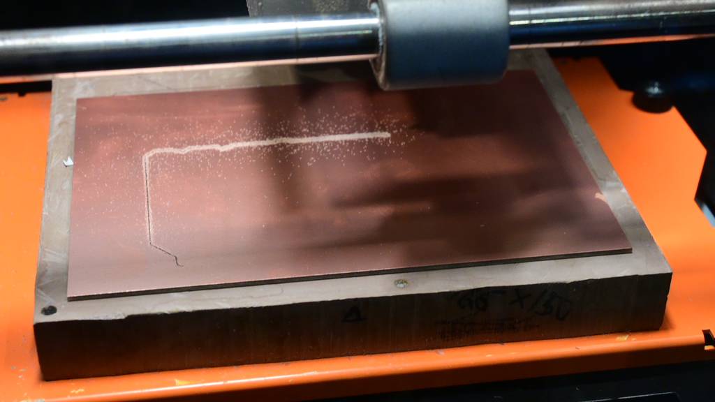
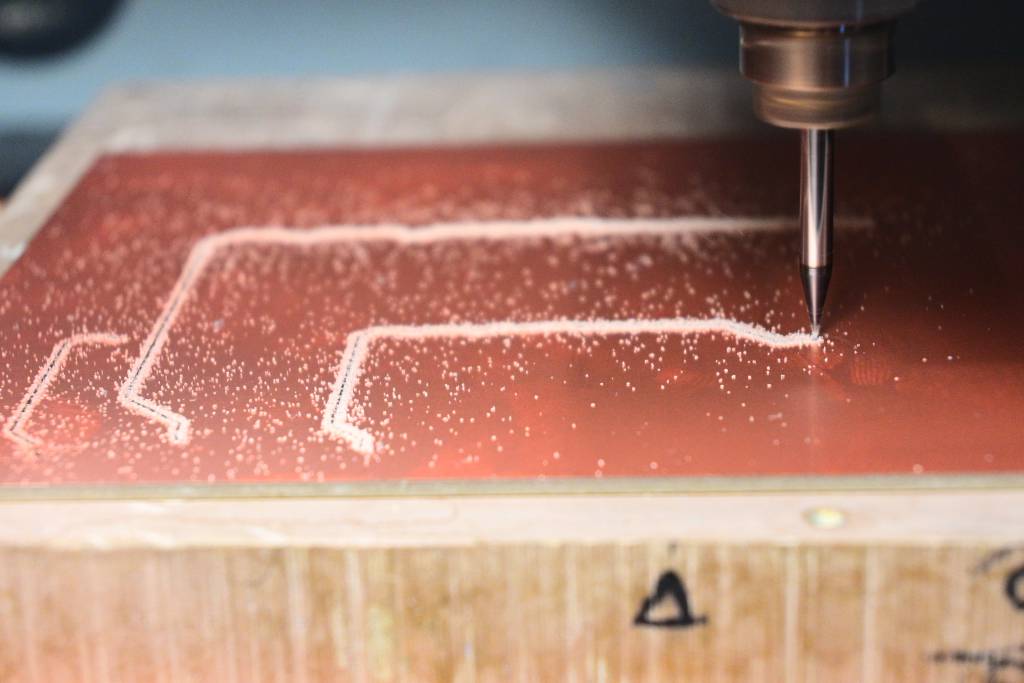
Milling the Board X2
This is a failure that caught me before, and in a time-pressured workflow it came up again:
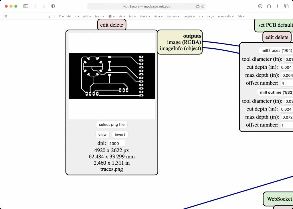
The 2000dpi Problem
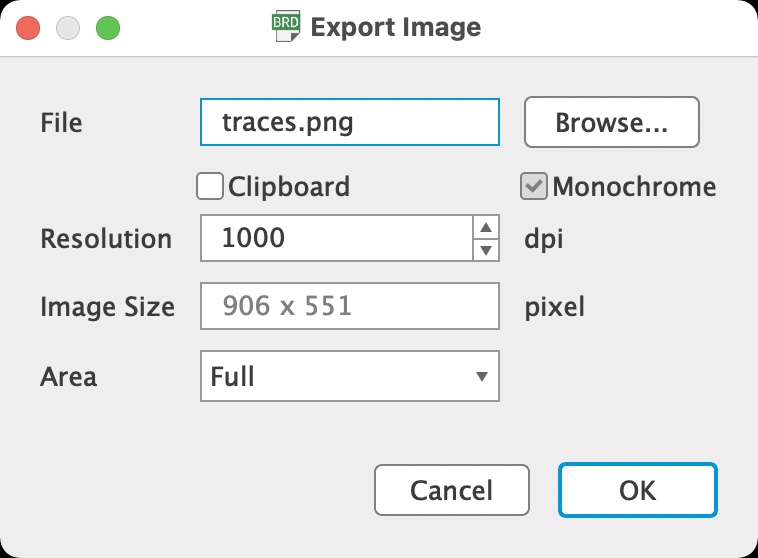
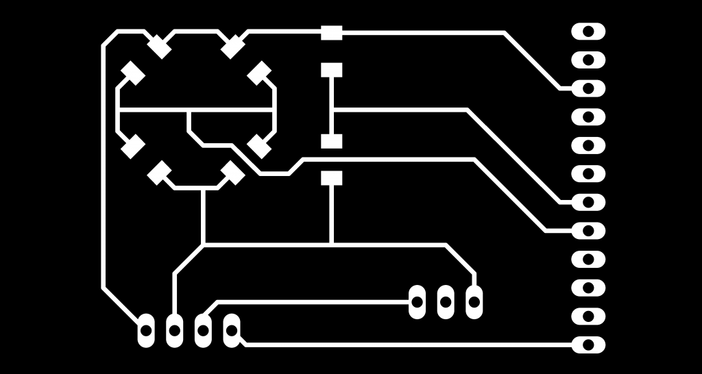
Exporting a 1000dpi Image from EAGLE
Importing to mods
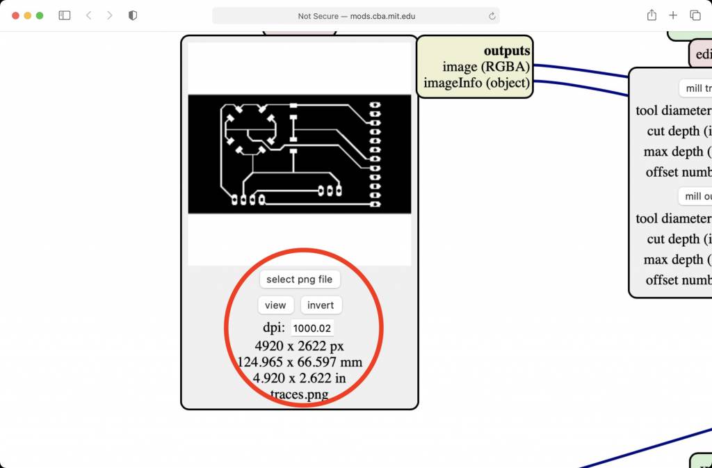
The image is read into mods, the dpi settings seems to be correct - 1000dpi.
BUT: The image dimensions are wrong: The board size of 124mm x 66mm is NOT correct. It should be 62mm x 33mm
OSX, Retina Displays and Physical Pixel Dimensions
-
The PNG format has a setting for Physical Pixel Dimensions, which encodes the absolute or relative dimensions of pixels.
-
Retina Displays have a setting of 144dpi, doubling the standard 72dpi of traditional screens.
-
This doubling of dpi is somewhere interfering with OSX, Eagle Export and mods Import, leading to displaying the correct dpi, but calculating the wrong dimensions.
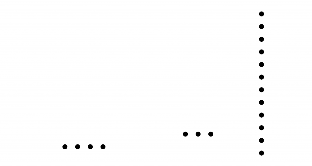
EAGLE and Pins
Where is the space between the pinheads and the edge coming from?

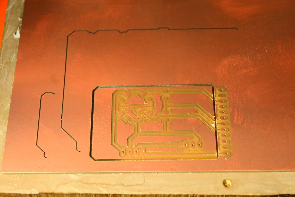
I went ahead an milled it. A mistake.
OLED & Temp Board
Which OLED?
For the output device I wanted to use an OLED, these are available at my favourite shop in Akihabara:
| Name, Type | Voltage | Price* | Address | Pull-Up? | Pin Order | Link & Datasheet |
|---|---|---|---|---|---|---|
| 0.96 OLED, 128x64 P-1580 | 3 - 5.5V | ¥580 | 0x78 (0x7A) | Internal | GND, VCC, SCL, SDA | Akizuki |
| 0.96 OLED, 128x64 P-12031 | 3.3 - 5.5V | ¥580 | 0x78 (0x7A) | Internal | GND, VCC, SCL, SDA | Akizuki |
Basically the same, the P-1580's display color is blue, the P-12031's display color is white. They both use the same internal SSD1306 controller chip, which also corresponds to the Adafruit SSD1306 library.
Temperature Sensors
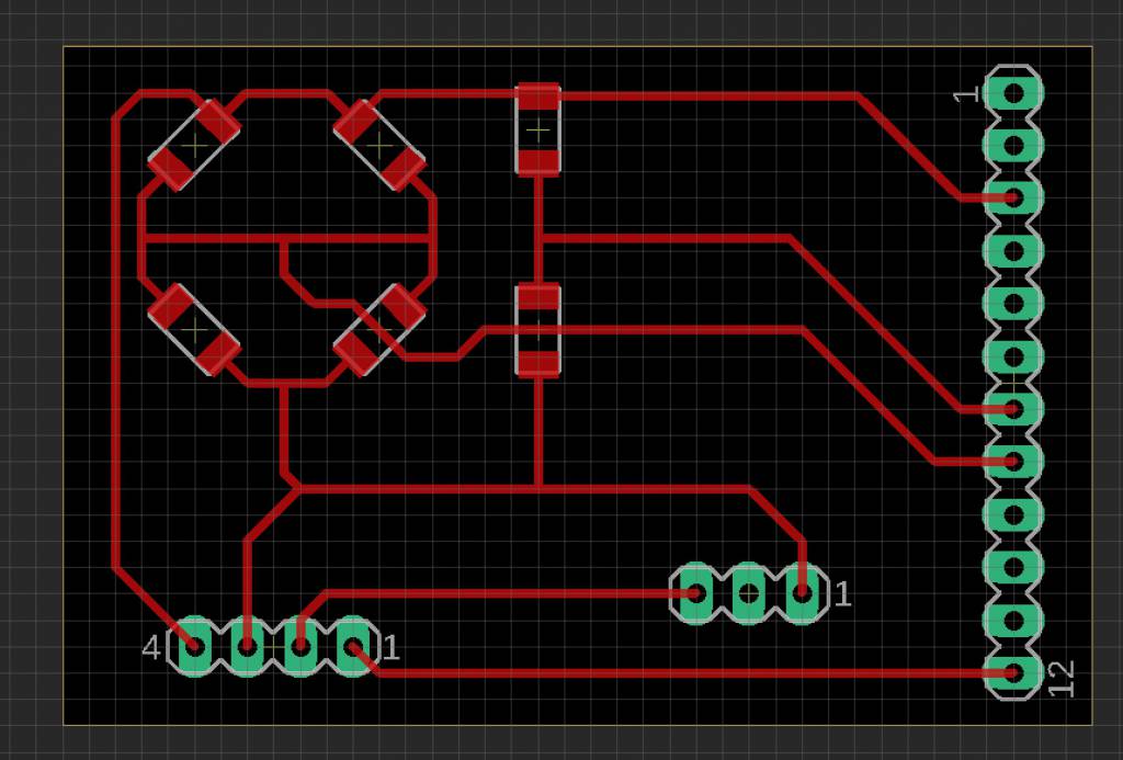
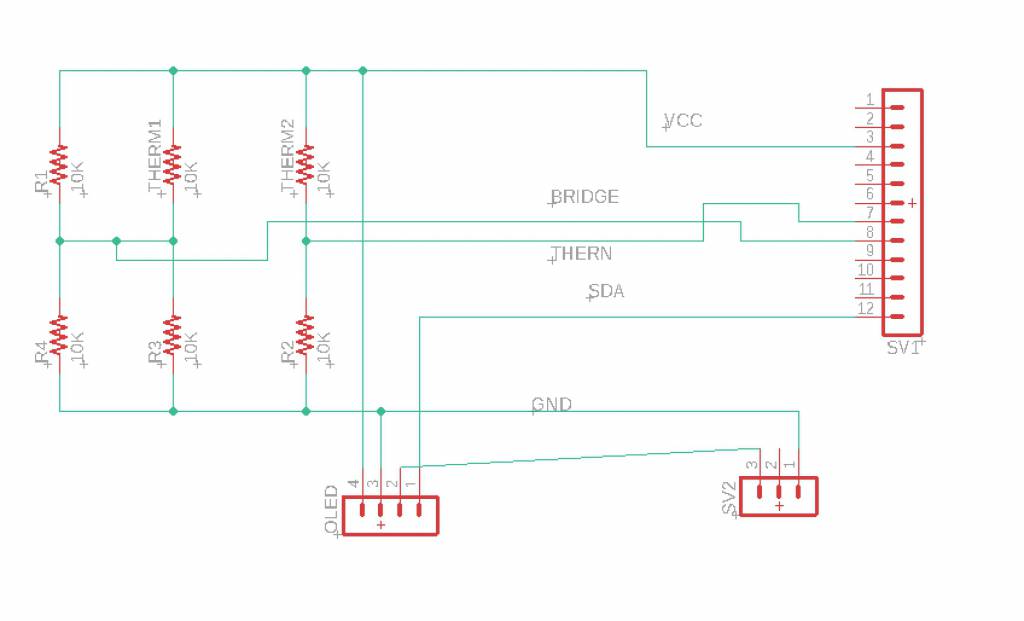
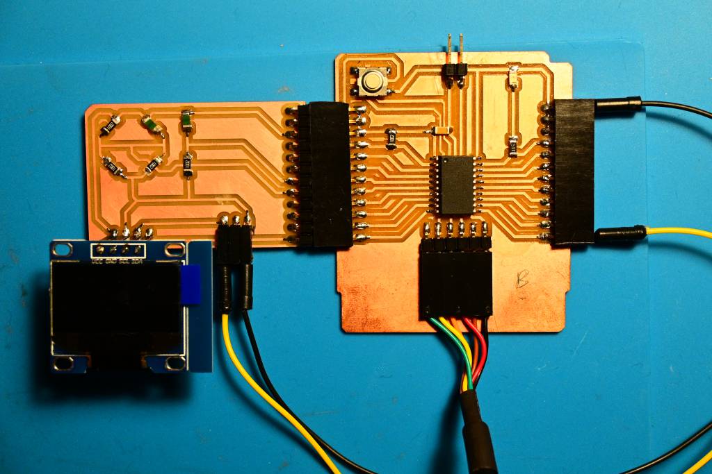
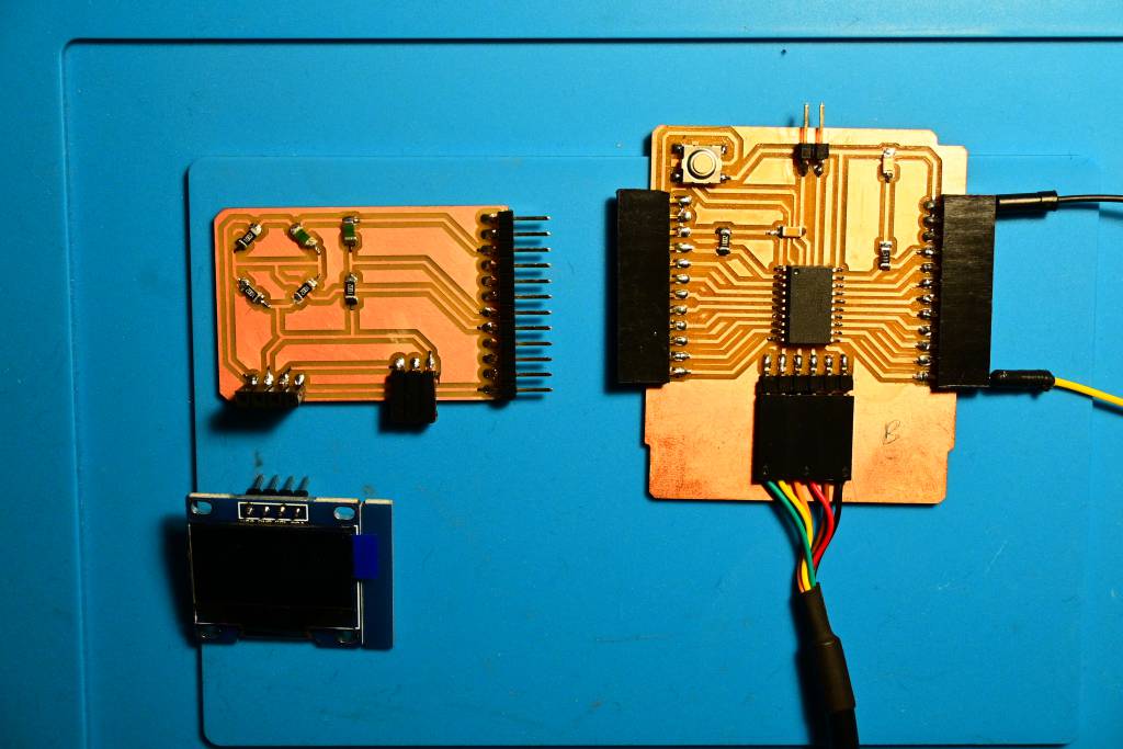
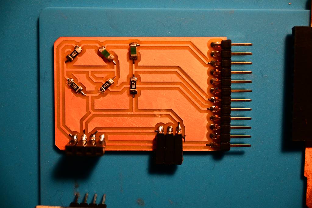
I covered the Wheatstone Bridge in details in Week 11, this breakout board for my ATTiny 3216 contains:
- A Voltage Divider Temperature Sensor
- A Wheatstone Bridge Temperature Sensor
- An I2C Connector for the OLED Display
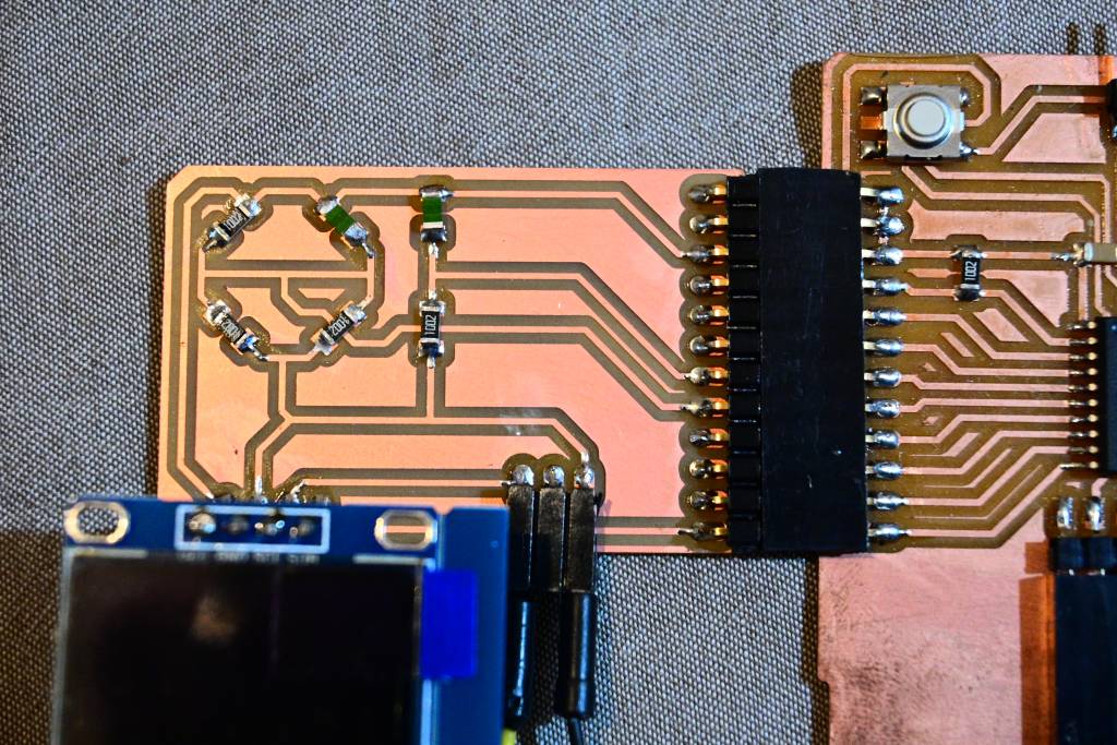
The Temp & OLED Breakout Board


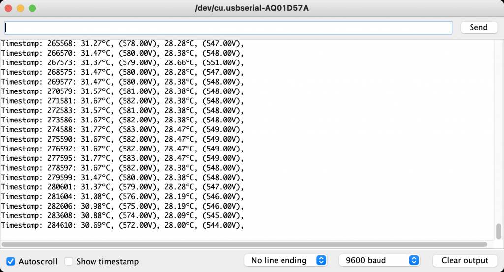
Serial Communication with the Board
I was using the Arduino IDE Build-in Serial Monitor to monitor the board, but the constant switching between the programmer and the board started to annoy me.
Arduino IDE Serial Monitor
Screen
The GNU Screen utility should be installed on your Linux or Unix-like OS. Screen is a full-screen window manager that multiplexes a physical terminal between several processes, typically interactive shells. If it's not installed, and you are on a OX, install it with:
brew install screenAnd call it simply with:
screen /dev/tty.usbserial-D307OEPA 9600/dev/tty.usbserial-D307OEPA is the path to your device, 9600 is the baud rate you want to use for communication.
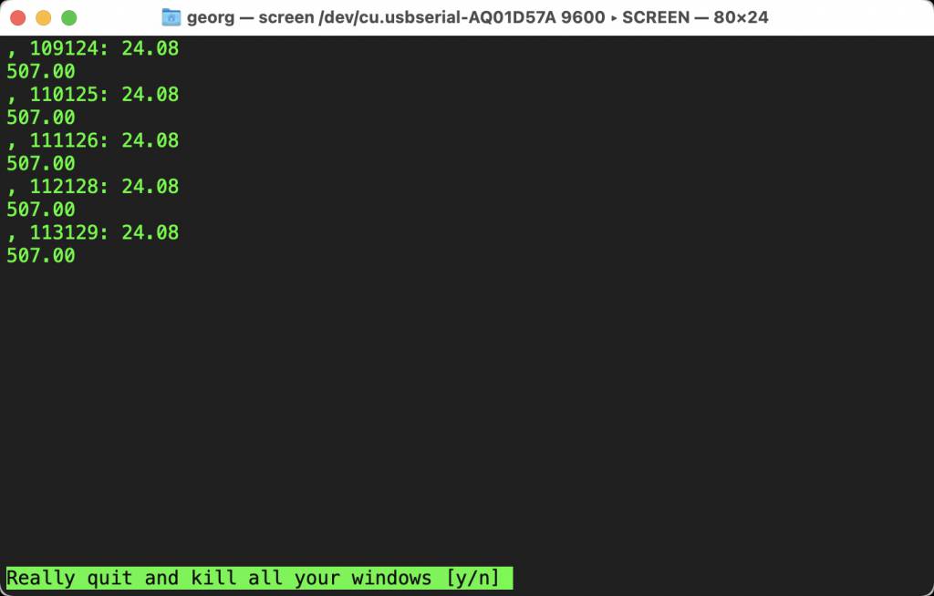
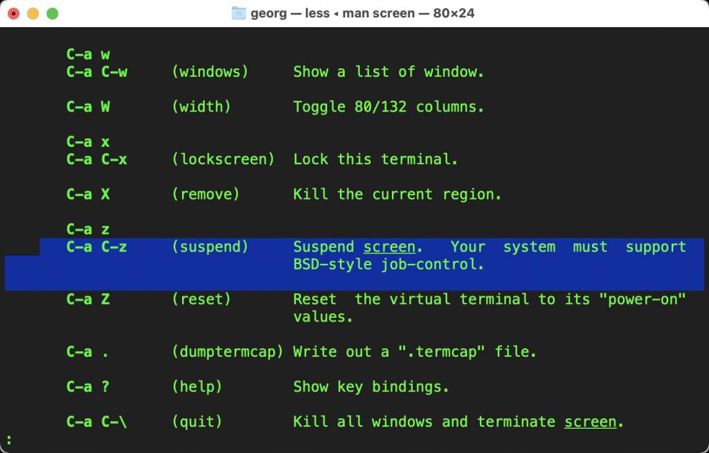
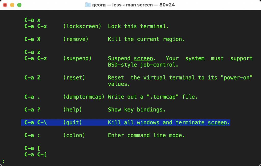
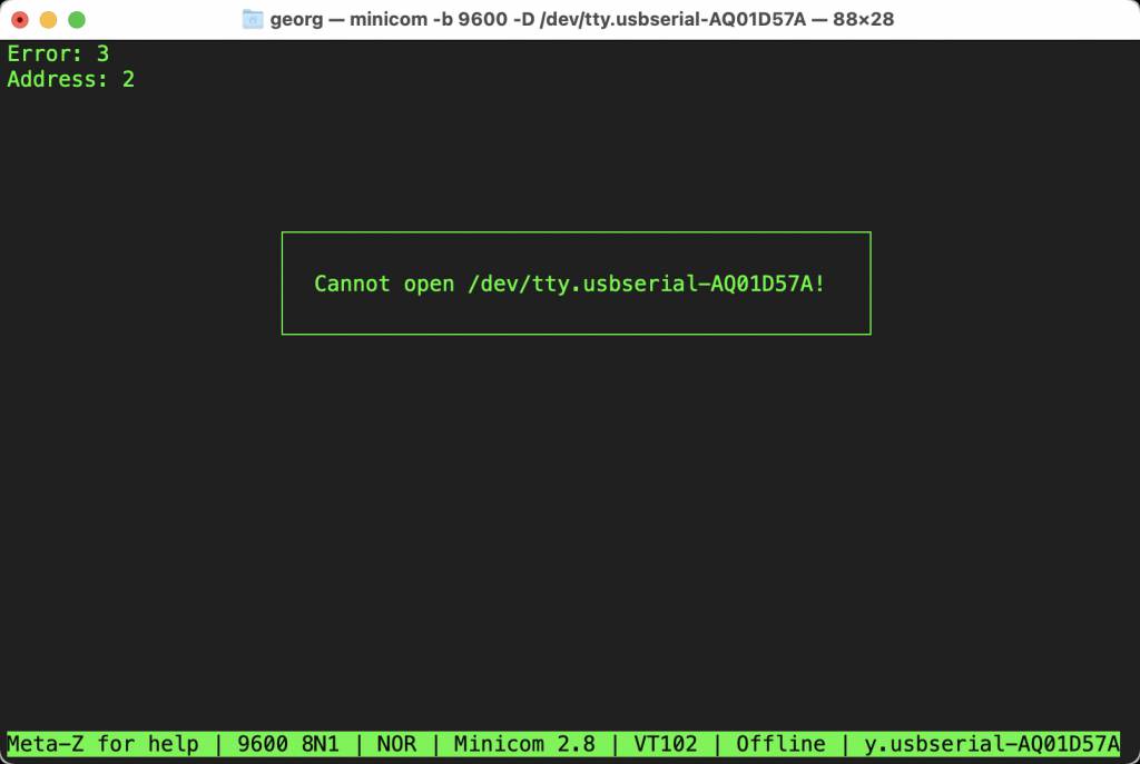
The challenge was to find the exit from screen. Terminating the session would result in an resource busy error, which can be solved by unplugging and replugging the USB connection. Not really ideal.
Minicom
Minicom is another serial monitor, slight more friendly UI.
On OSX install it with:
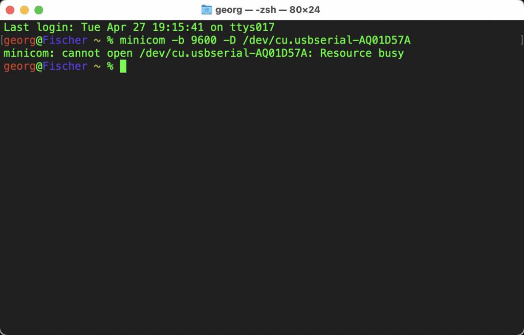
brew install minicomYou need to know which serial device you want to communicate with. Use lsusb to find the device name.
-bsets the baudrate-Dsets the device
minicom -b 9600 -D /dev/tty.usbserial-D307OEPA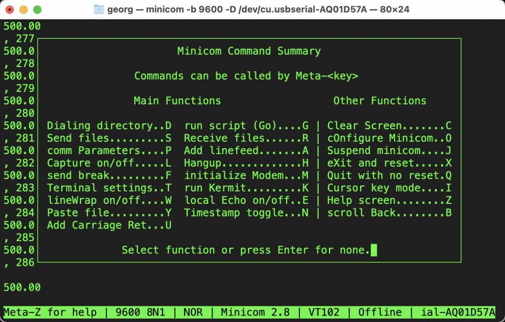
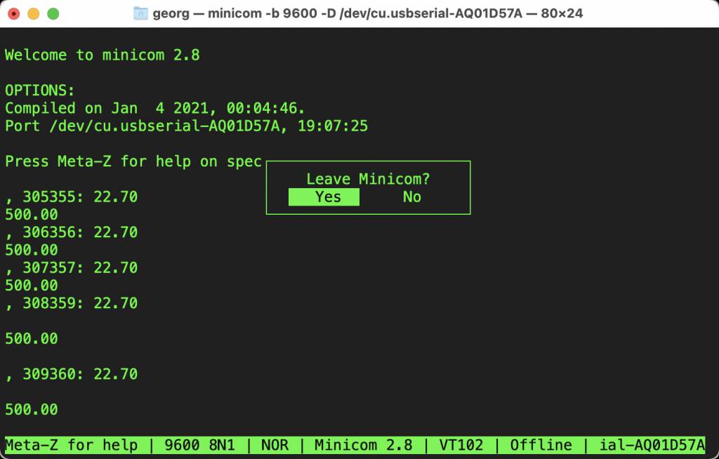
- Minicom can be exited with the standard
Ctrl Z.
Temp Sensing & OLED Output Code
I used the Arduino IDE to connect the Thermistors to the OLED. The code for the Thermistors was developed during the Input Week
#include <Adafruit_GFX.h>
#include <Adafruit_SSD1306.h>
#define SCREEN_WIDTH 128 // OLED display width, in pixels
#define SCREEN_HEIGHT 64 // OLED display height, in pixels
#define OLED_RESET -1 // Reset pin # (or -1 if sharing Arduino reset pin)
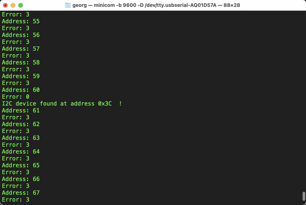
#define SCREEN_ADDRESS 0x3C ///< See datasheet for Address; 0x3D for 128x64, 0x3C for 128x32
Adafruit_SSD1306 display(SCREEN_WIDTH, SCREEN_HEIGHT, &Wire, OLED_RESET);
int Sensor1_PIN = 3; // Voltage Divider
int Sensor2_PIN = 4; // Bridge Therm
int SDA_PIN = 8; // I2C Pin Definition
int SCL_PIN = 9; // I2C Pin Definition
float R25 = 10000;
float B = 3750; // B25/85 3750K
float V, R, T;
float V2, R2, T2;
unsigned long timeStamp;
void setup() {
Serial.begin(9600);
// SSD1306_SWITCHCAPVCC = generate display voltage from 3.3V internally
if(!display.begin(SSD1306_SWITCHCAPVCC, SCREEN_ADDRESS)) {
Serial.println(F("SSD1306 allocation failed"));
for(;;); // Don't proceed, loop forever
}
display.display();
delay(2000); // Pause for 2 seconds
// Clear the buffer
display.clearDisplay();
// Draw a single pixel in white
display.println("FabAcademy 2021");
display.display();
delay(2000);
}
void loop() {
timeStamp = millis();
V = analogRead(Sensor1_PIN);
/* V = 1024.0 - V; // invert V, wrong placement of the thermistor */
R = R25 * (1024.0 / V - 1.0);
T = 1.0 / ( log(R/R25) / B + (1/(25.0 + 273.15))) - 273.15;
V2 = analogRead(Sensor2_PIN);
R2 = R25 * (1024.0 / V2 - 1.0);
T2 = 1.0 / ( log(R2/R25) / B + (1/(25.0 + 273.15))) - 273.15;
// display code for the SSD1306 libray
display.clearDisplay();
display.setTextSize(3);
display.setTextColor(SSD1306_WHITE);
display.setCursor(0,0);
display.println("Temp1:");
display.print(T1);
display.println("Temp2:");
display.print(T2);
display.display(); // actually display all of the above
delay(2000);
}
OLED Troubles & Solution
OLED & 3216
I could not get the OLED Display to work with my 3216 board.
Once challenge I2C has, is the variation in Pin assignment, my debugging process started with checking and double-checking that I connected the correct I2C pins from the OLED to the board.
I did, still not working.
Next step: eliminate another source of error, try to use the OLED with another microcontroller.
OLED & Arduino
I resorted to testing it with an Arduino UNO.
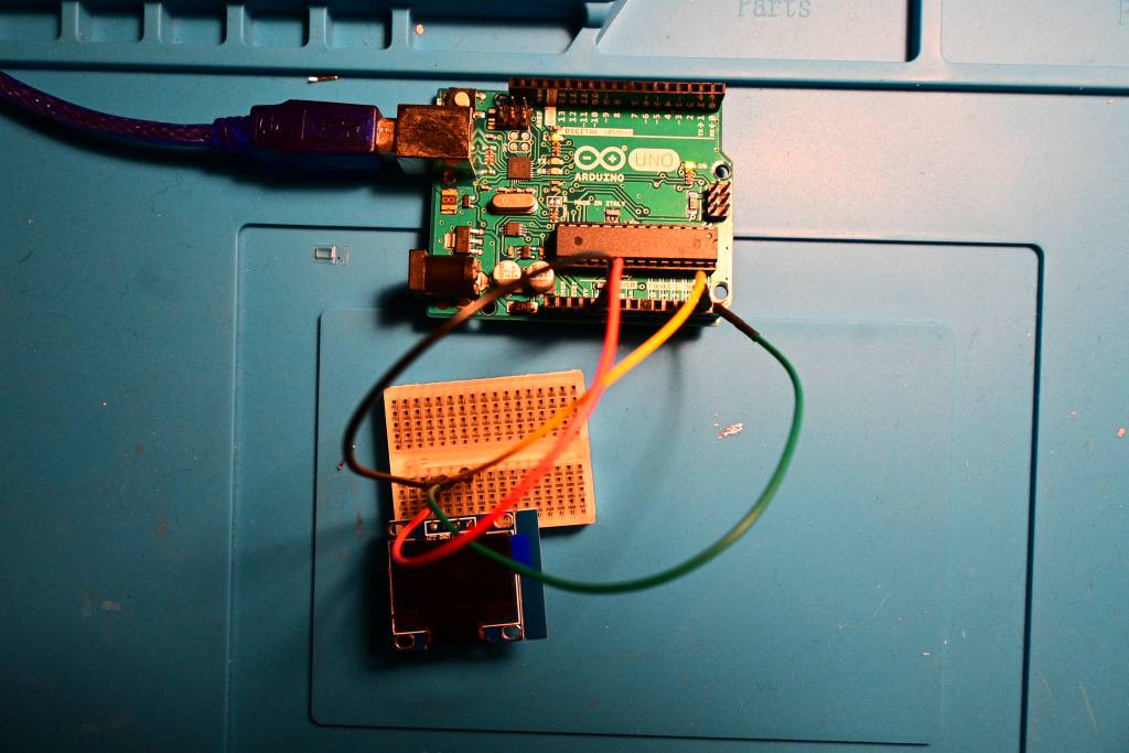
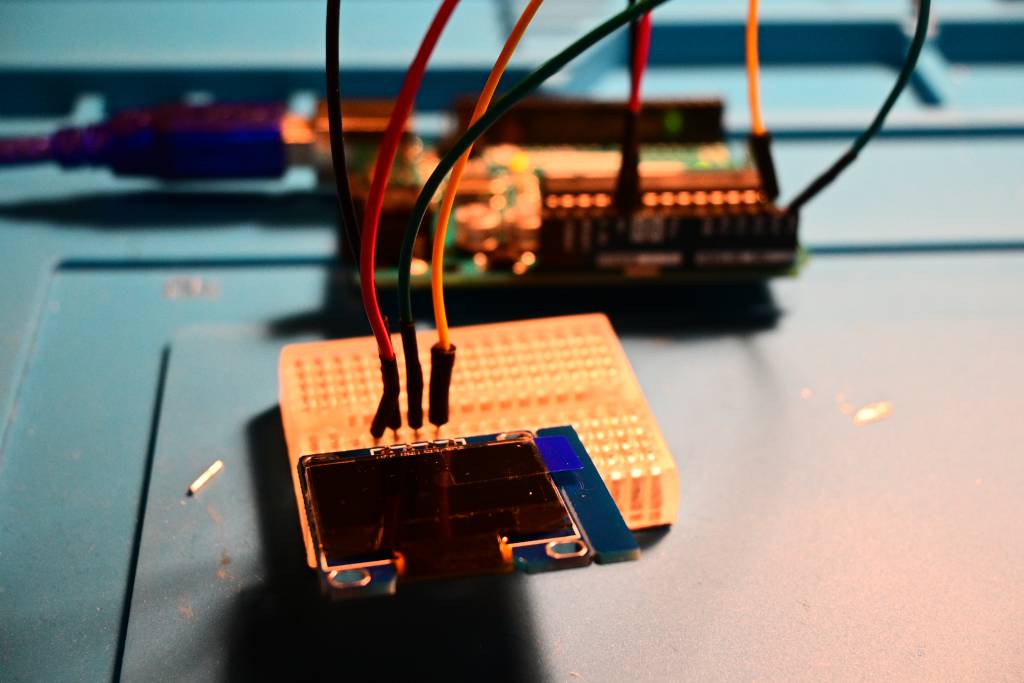
Also did not work.
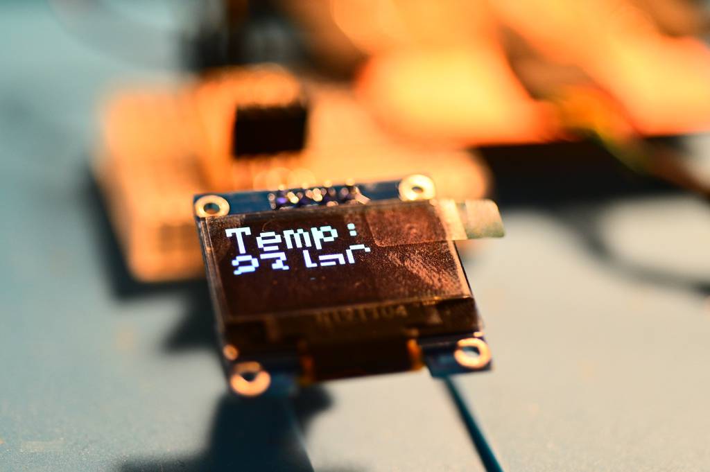
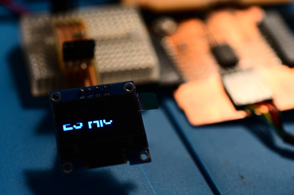
Another OLED Display
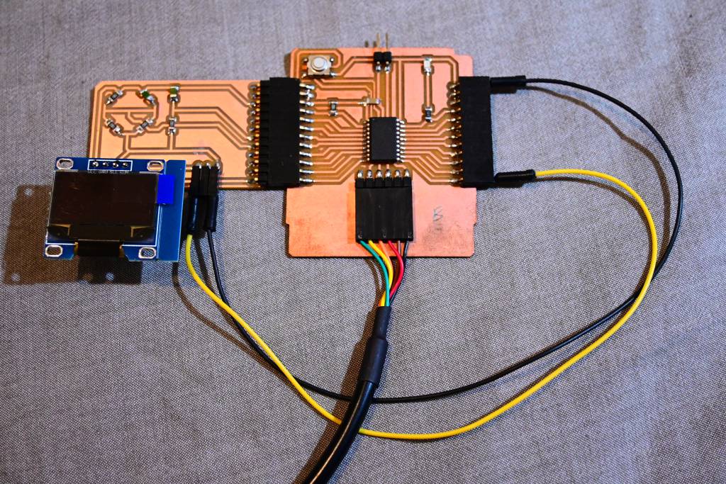
I got another OLED Display.
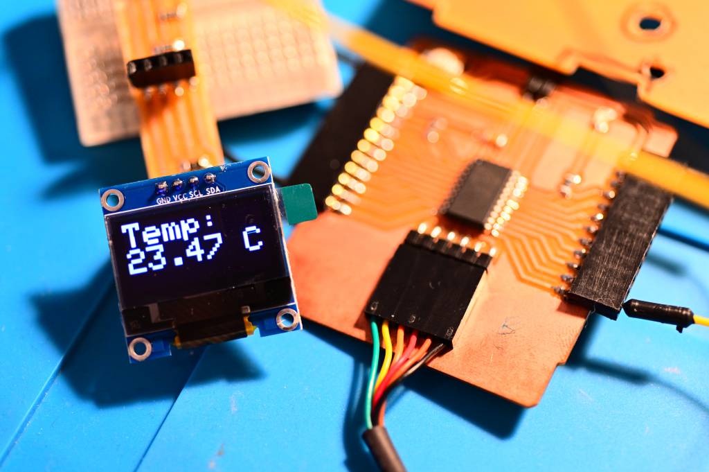
This time it works!
Hero Images
Learning Outcome
This week was Output Week, but it was a minimal test run for my Final Incubator Project. I encountered and mastered some hurdles in the Circuit Board production process, hopefully the last one. I also got introduced to hardware debugging - and learned that you can not trust devices (OLEDs!) to work.
One key thing to remember, is that different output devices have different voltage and current requirements. Always double (triple) check this.