Week 11 : Molding & Casting
☛ Group Assignment
☐ 1. Review the safety data sheets for each of your molding and casting materials, then make and compare test casts with each of them
☛ Individual Assignment
☐ 2. Design a mold around the stock and tooling that you'll be using, mill it (rough cut + (at least) three-axis finish cut), and use it to cast parts
☛ Group Assignment
▸ Safety measures
We began the week by testing different kind of casting materials we have at the fablab : several silicones, epoxy resin, and "liquid plastic". Before that we equiped ourselves with gloves, masks, glasses and a protective suit. These materials are hazardous for our health, they may cause :
- Skin irritation / allergic reaction.
- Eye severe irritation.
- Respitory irritation : these products are toxic
- Breathing difficulties or allergy and asthma symptoms if inhaled.
- If in contact with the skin : Wash your hand/skin in contact with the product with a lot of water and soap.
- If inhaled : Leave the room and go breathe fresh air for a moment.
- If irritations of the skin or of the eye occurs, seek for medical advice. Don't forget the product label.
- If respitory symptoms occurs, call a poison center.
If any of it occurs, some response precautions are to :
When using these products the safety equipment is required, and the ventilation is an important parameter for the place you will cast in. Also those product should be stored in a ventilated place and locked up (particularly if children can access the lab, or the home lab).
▸ Testing casting materials
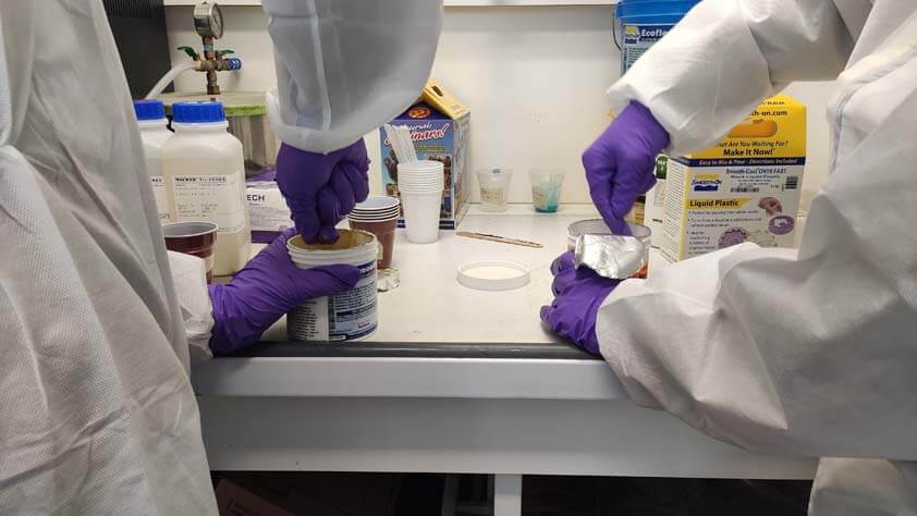
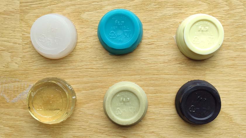
Then we started stirring and pouring 20g for each material into plastic cups in order to practice the casting process, here are the materials and general informations about them :
- Pot life is the time you have to pour it once materials A and B are mixed
- Cure time is the time the material will take to dry, some materials, as reisn, mays require more time to dry completely after this.
- Mix ratios are the ratios to respect when mixing the A and B parts, as the products have different densities the volume ratio and weight ratio are different too.
- Shore hardness is an indicator of the material hardness from 0 to 100, it exists different scale to measure it : The Shore 00 scale measures very soft materials, like the Ecoflex 00-30 we used, the Shore A scale measures several material types (soft, medium-soft, medium-hard and hard), and the Shore D scale measures hard rubbers.
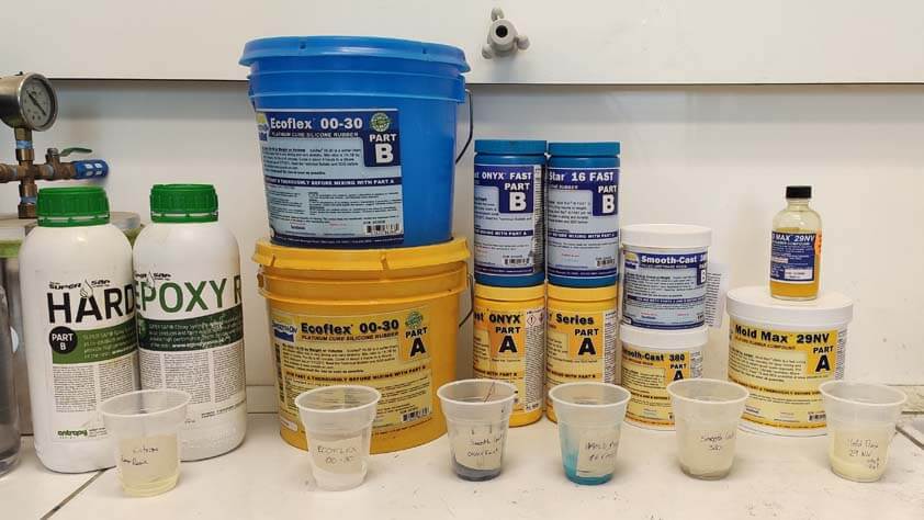
During this session we tried these materials :
| Materials tested | Pot life | Cure time | Mix ratio | Mix ratio by weight | Shore hardness | Color |
|---|---|---|---|---|---|---|
| Ecoflex 00-30 | 45 minutes | 4 hours | 1A:1B | 1A:1B | 00-30 | Translucent |
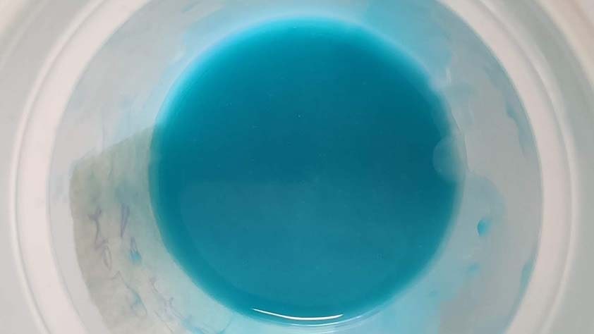
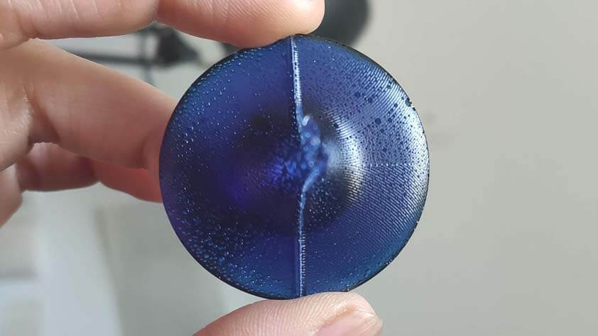
| Mold Star Fast 16 | 6 minutes | 30 minutes | 1A:1B | - | 16A | blue |
| Materials tested | Pot life | Cure time | Mix ratio | Mix ratio by weight | Shore hardness | Color |
|---|---|---|---|---|---|---|
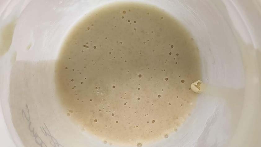
| Smooth Cast 380 | 6 minutes | 60 minutes | 1A:1B | 1A:1B | 82D | tan |
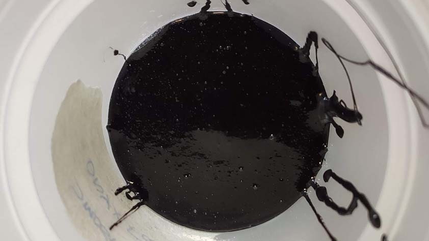
| Smooth Cast ONYX FAST | 2.5 minutes | 15 minutes | 100A:100B | 120A:100B | 82D | black |
| Materials tested | Pot life | Cure time | Mix ratio | Mix ratio by weight | Shore hardness | Color |
|---|---|---|---|---|---|---|
| Epoxy Super Sap | 15 minutes | 4 hours | 200A:100B | - | 70-80D | black |
| MOLD Max 29NV | 40 minutes | 6 hours | - | 100A:10B | 29A | yellow |
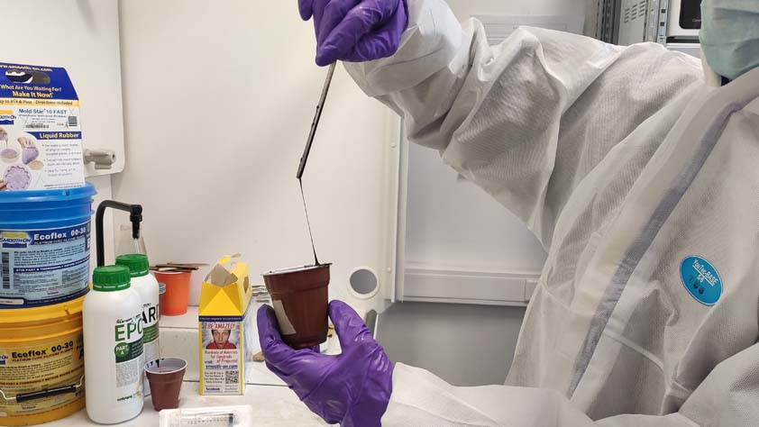
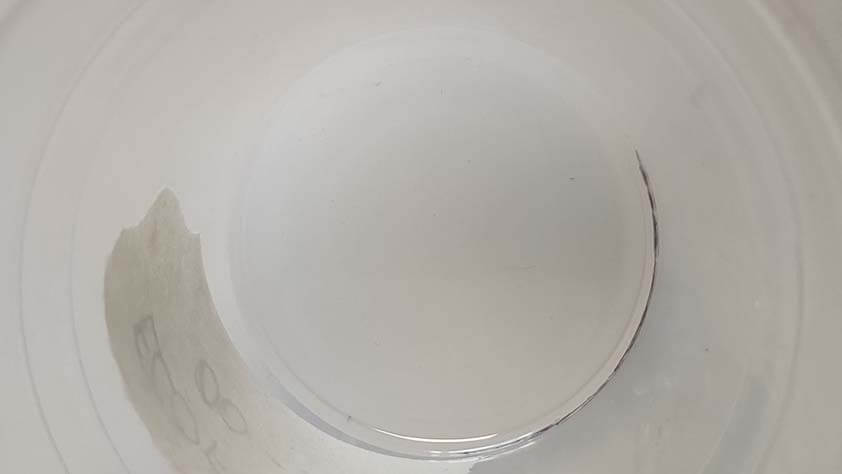
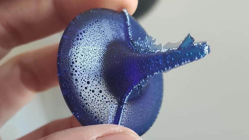
This was fun. And the most surprising mix was the Onyx (super) fast one, as soon as the parts are mixed, there is 2.5 minutes of pot life, the picture above shows the mix already drying as we pull up the stirrer.
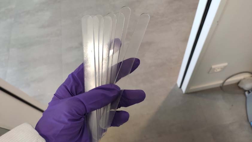
We thought the mixes will take volume, but it didn't occured as stroke we draw on cup after pouring the products was not crossed. And on the image below on the left, this is stirrers we lasercutted in 2mm acryclic as we didn't have enough of it.
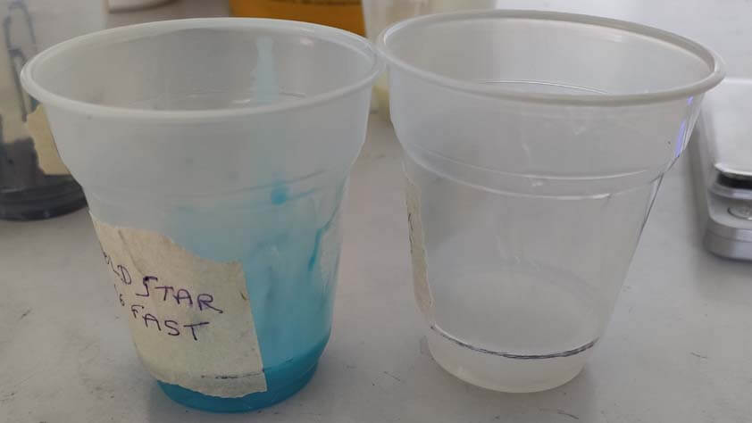
Our tests demolded from their cups.
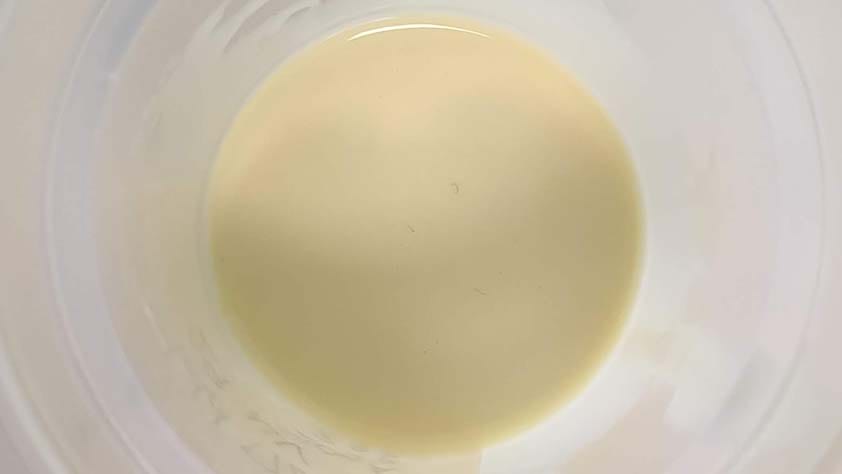
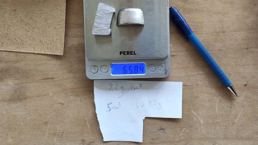
This is a resin that looks like "glass", it used to make jewelry I had at home for several years, here is a sample of it :
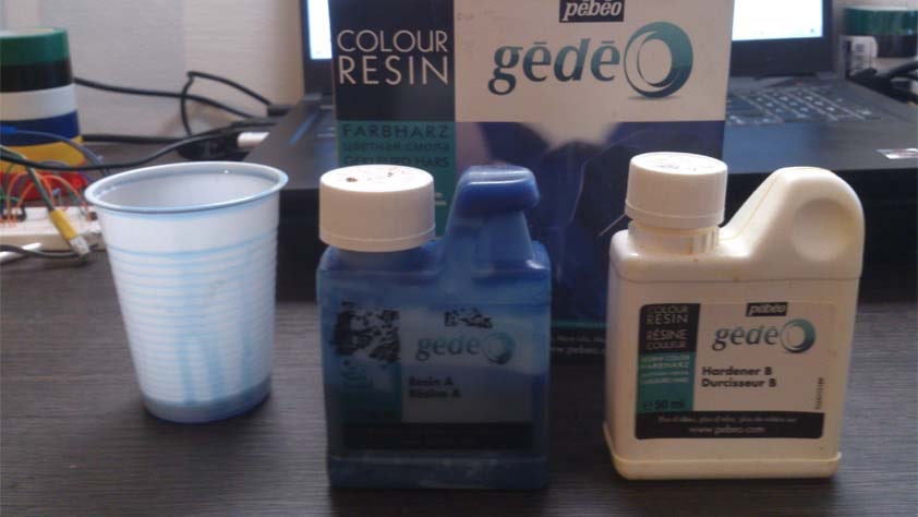
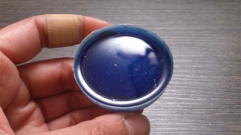
| Materials tested | Pot life | Cure time | Mix ratio | Mix ratio by weight | Shore hardness | Color |
|---|---|---|---|---|---|---|
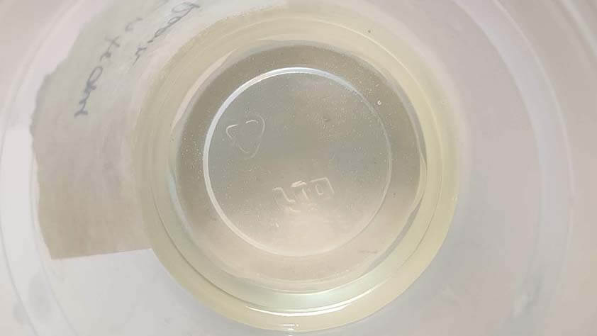
| Gedeo colour resin | ~30 minutes | 24 hours | 2A:1B | - | - | blue |
☛ Designing a mold
Next step is to design a mold to be milled in order to make a mold to be casted, here we go ~
▸ Our Tools
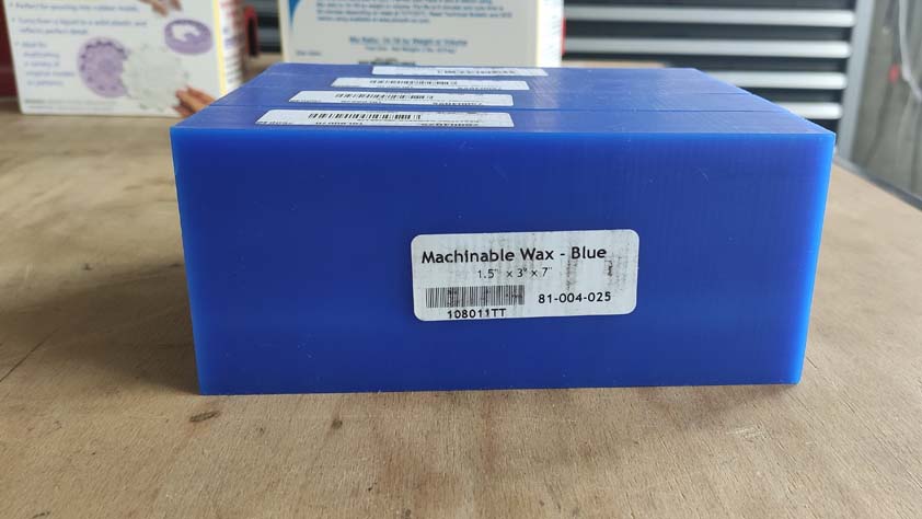
We will use Machinable Wax to mill our molds of molds in. What is great about Wax is that it can be melted and casted into a stock of wax again.
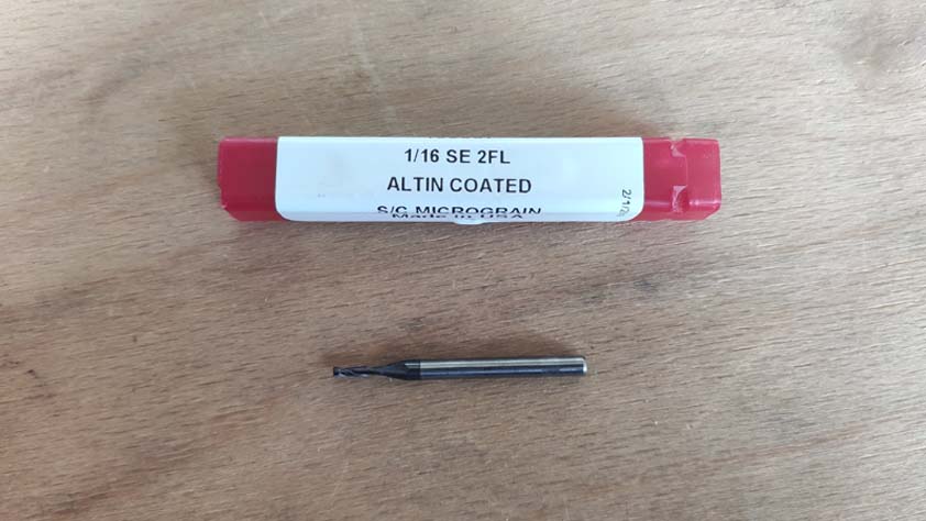
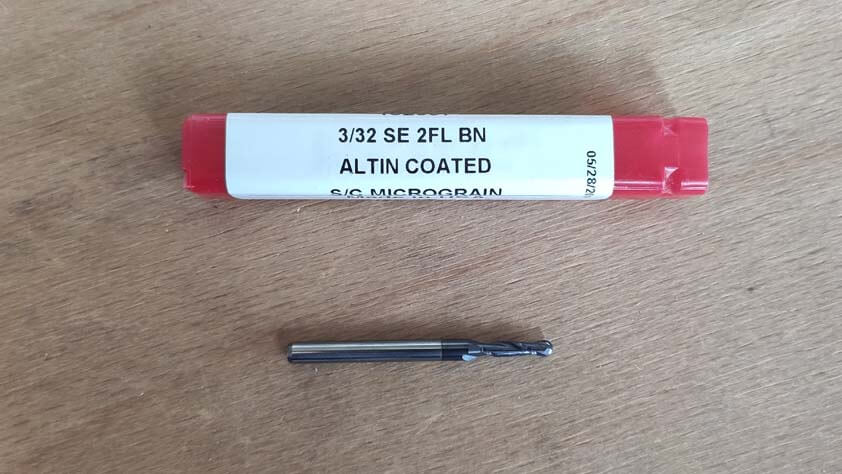
And here are the bits I will use to mill the Wax stock, a flat endmill for the rough mill, and a rounded one for the finish mill.
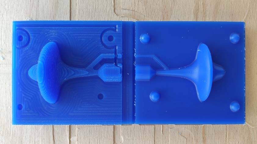
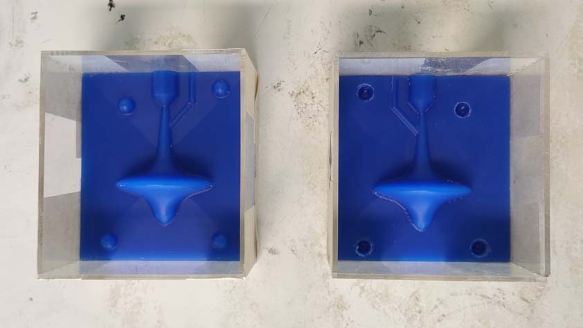
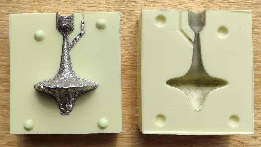
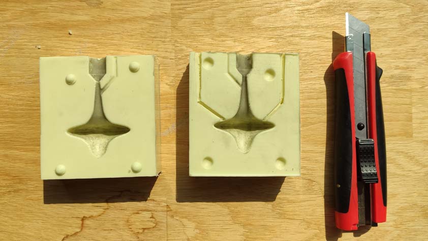
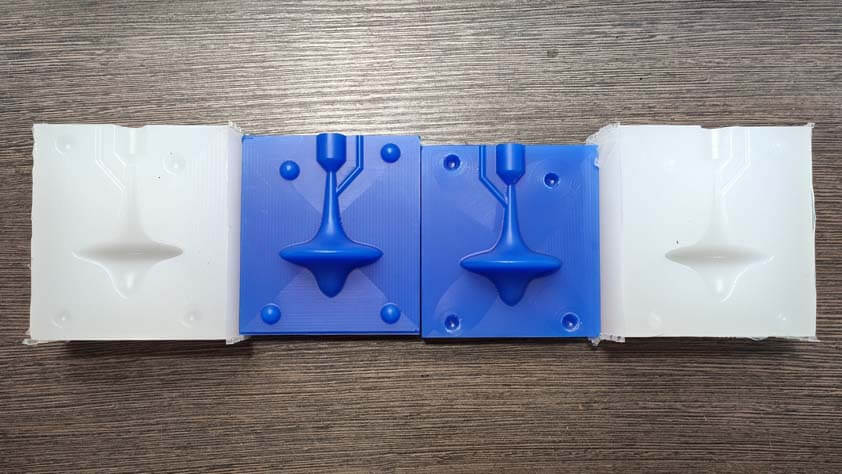
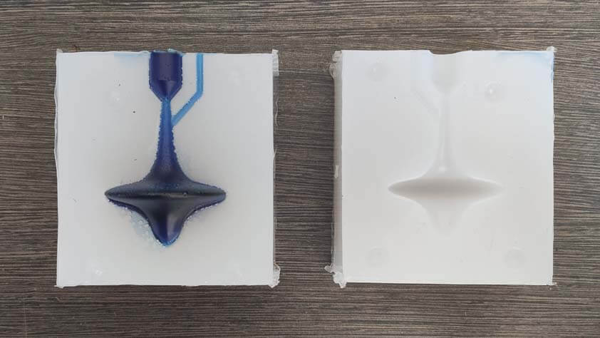
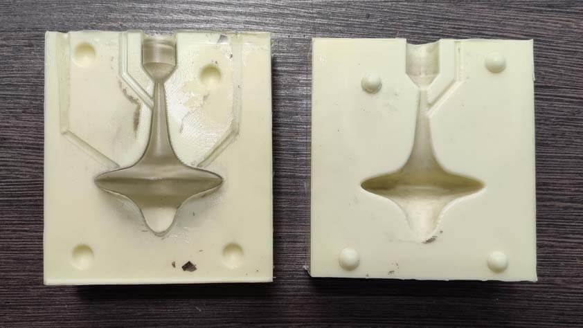
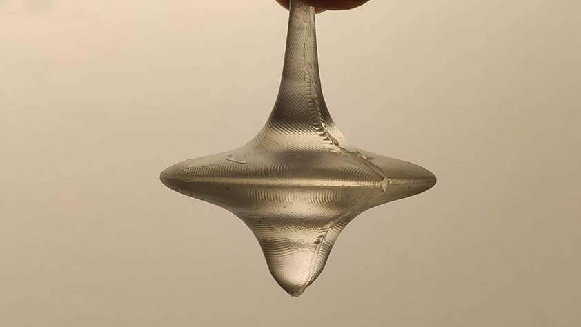
▸ The (not original but still) mold
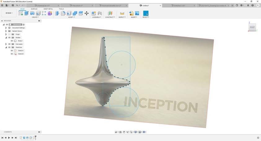
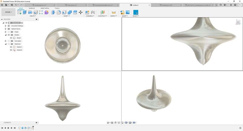
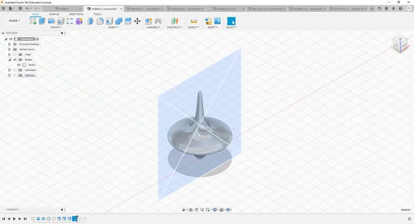
I decided to chose something simple to discover the 3D milling, I wanted to cast Cerrotru, and I thought a spinning top would be cool to try. I took an image from spinning top in Inception, copied its profile and revolved it to obtain the result shown above.
Then I prepared the mold to make my final object :
Create a rectangle in a sketch in the middle of the "final piece" wanted.
Extrude symetrically the rectangle around the final objec so it contains it.
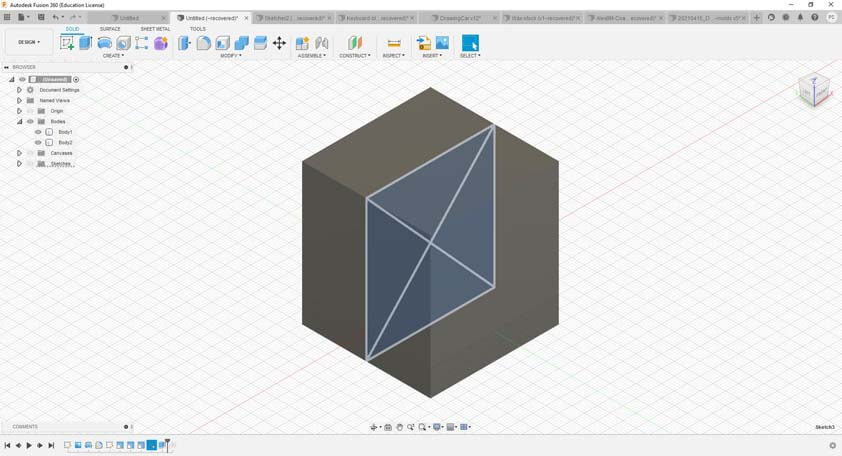
Open the combine menu, select the rectangle, then the final piece, and choose the "cut" option.
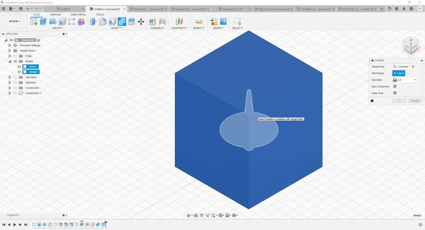
The next step is to create a construction plane and to place it in the middle of the final piece.
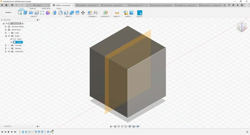
Open the Split body menu and select the construction plane as the cut axis.
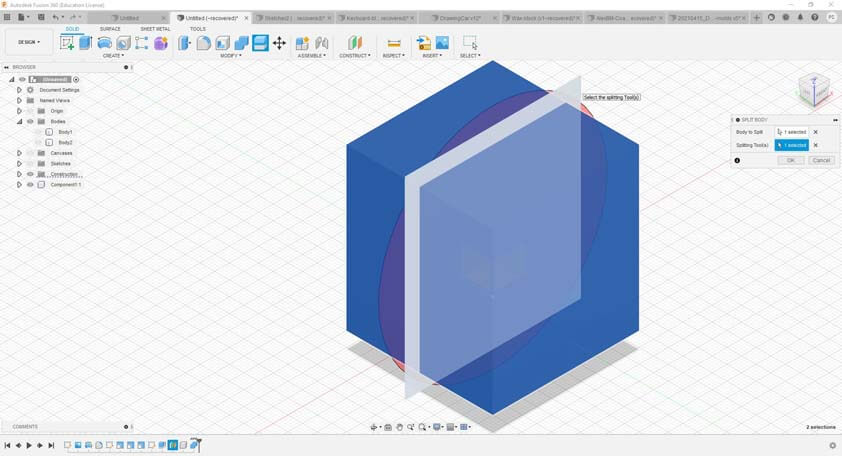
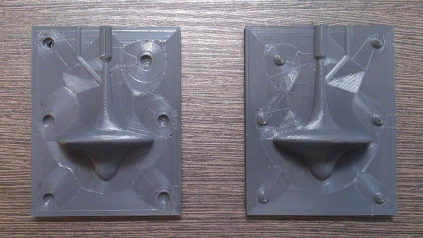
So now, here's a two parts mold, which is missing pipes and registration plot.
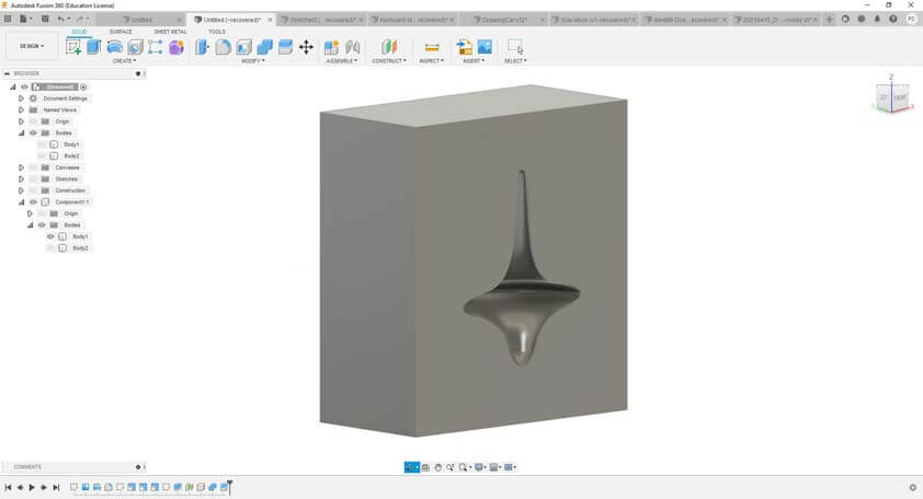
I added the air and pouring pipes, and the registration plots, then I reproduced the proces described above in order to make the mold of mold out of my final mold.
▸ Preparing the 3D Milling
Thankfully, we had a workshop about 3D milling during the Computer Contolled Machine's week, Alexandre Beaudouin explained and showed us his 3D milling practice, and it was a huge help for this week.
When the design is ready, in Fusion 360, you can switch to the Manufacture workplace and prepare your file for the CNC. The first step is to create a Setup, and then to prepares the jobs you want the machine to do.
In the setup, you have to specify the type of tool your using and its size, as it will generate a toolpath for this tool, and the size of your stock and the model(s) to be milled. The very important thing to parameter is the origin of your file, you select it in the "Work Coordinate System", it is different from the origin of the milling machine. The stock to mill has unique measures, therefore it has to be measured precisely.
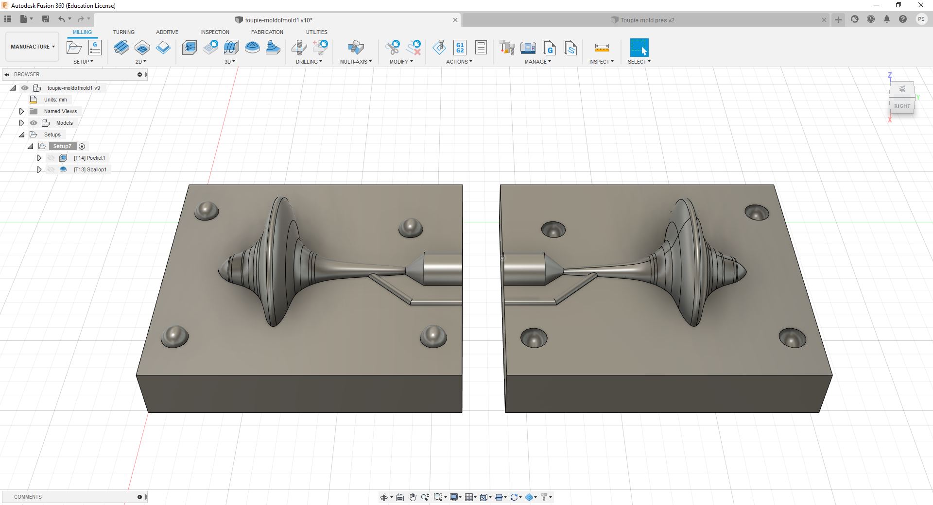
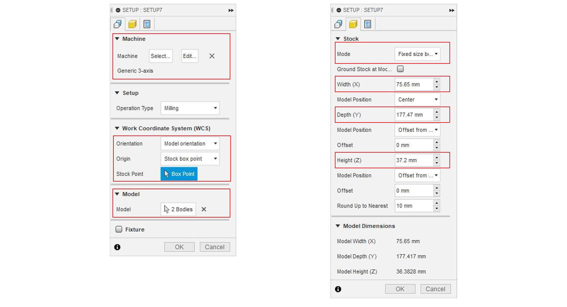
I selected the pocket as a rough mill, and here are my parameters. I had to offset the bottom of my stock so the machine collet won't touch the Wax stock when milling between my molds. In the fourth menu I selected the Manual Step Over and put it to 2mm, I also allowed the machine to leave 1.5mm of stock.
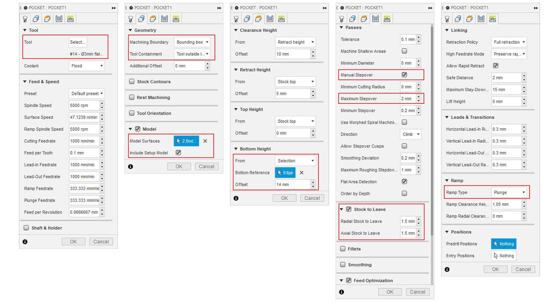
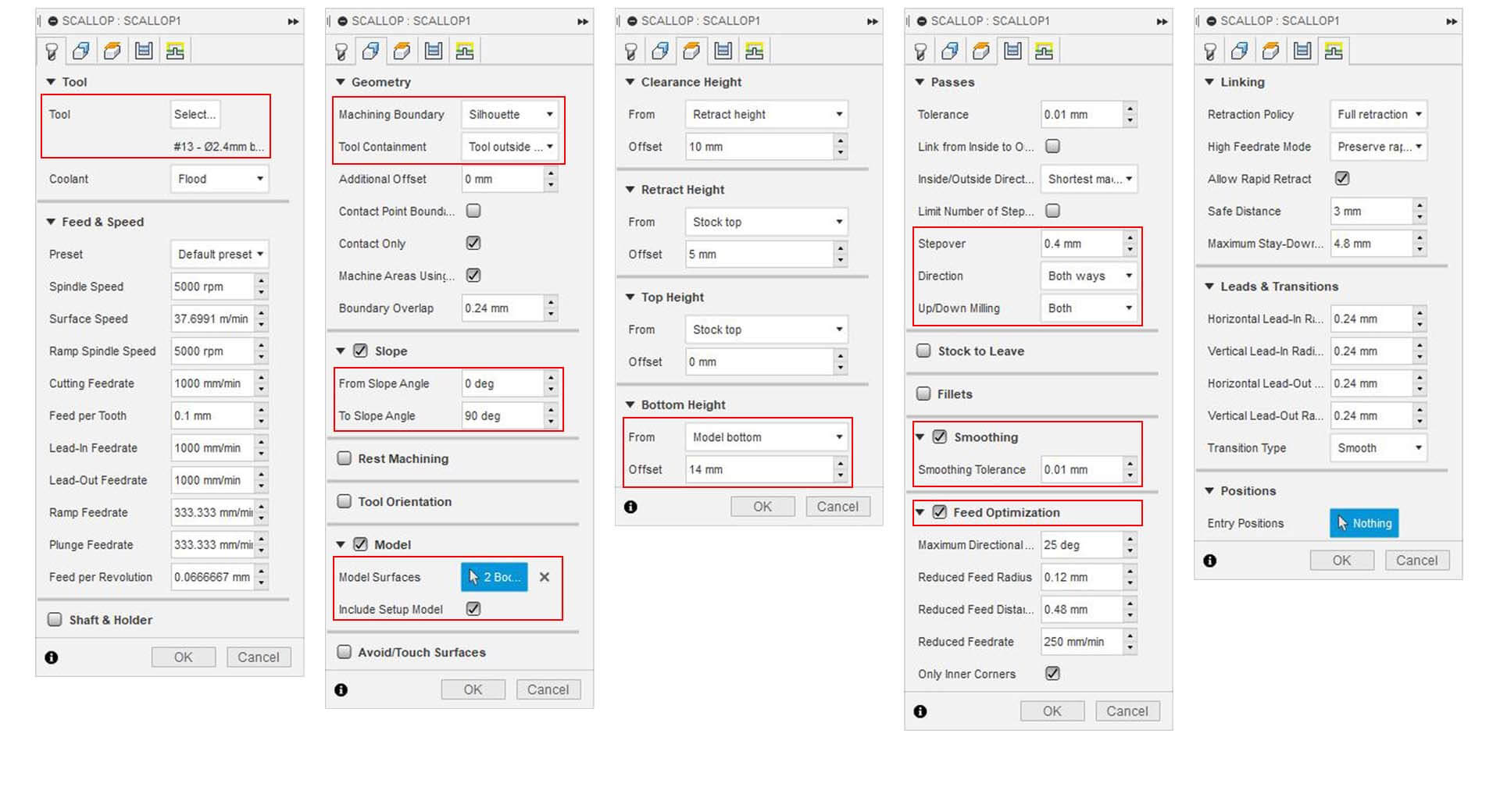
And here are the Scallop job parameters, the important parameter here is the step over which I set up to 0.4mm for a 2.4mm of diameter tool, lower is the step over, smoother is the finish milling result.
A very useful tool from the manufacture workplace in Fusion 360 it to be able to simulate the jobs - so you can have a preview of the work depending of the parameters you choose.
▸ 3D Milling
After the XYZ calibration on the stock (mind the origin and orientation of your piece, the Airpass is cool to verify that everything it set up properly), it's time to mill : Stay around the machine and watch it do its magic. And be ready to stop it if it goes wrong.
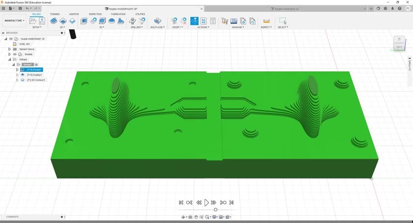
Here is the rough mill in process :
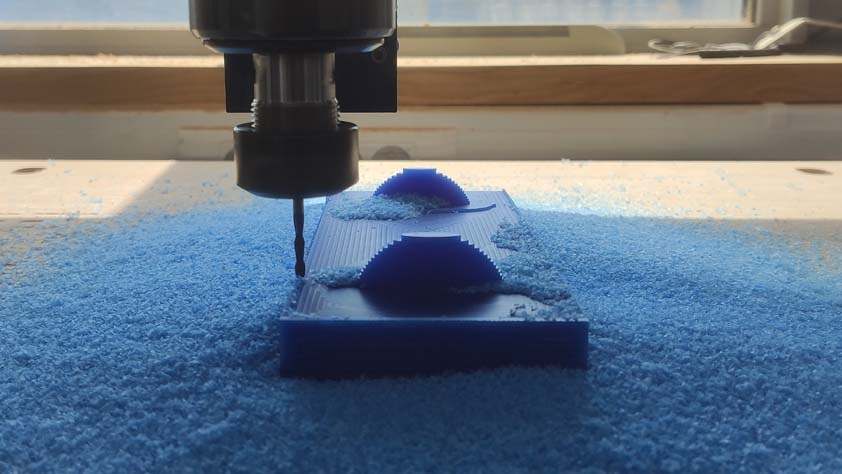
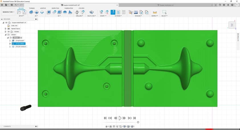
These shapes are so cool, and watching the CNC milling is a satysfying experience. On the image on the right below, the finish process has begun.
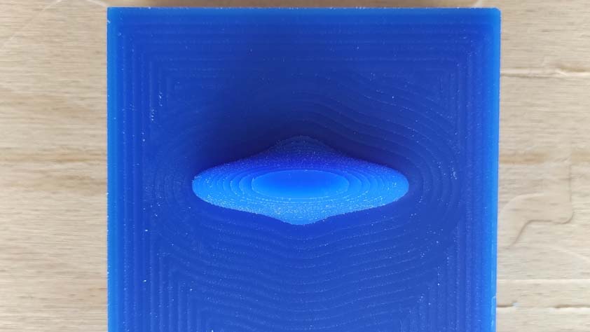
Here is the stock of Wax in the middle of the finish mill :
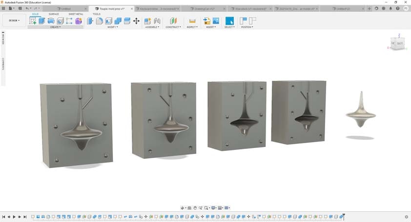
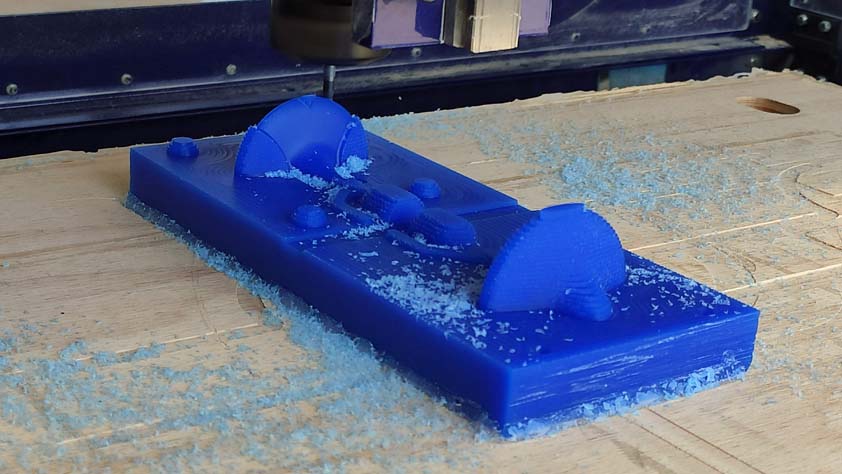
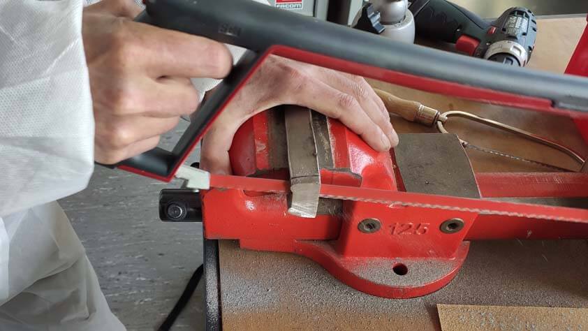
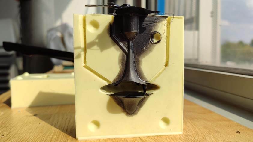
I used a saw to cut my molds out of the stock. I could have done it using the CNC but the rough cut and finish cut had already took 4 hours so I decided to not monopolize the machine more. As a post process, I had to use the Dremel in order to do my registration holes, as I didn't find the right parameters in Fusion 360. I hope this won't cause issues in the casting steps.
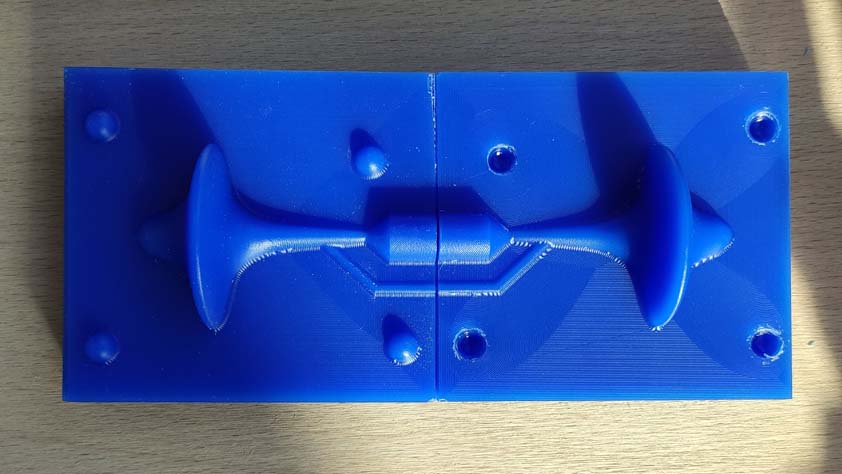
And here is the final result of the 3D milling part :
☛ Casting
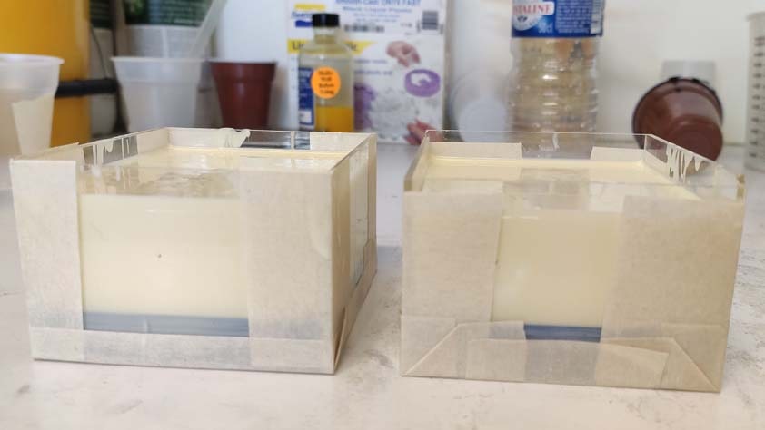
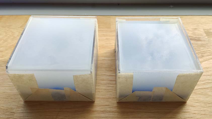
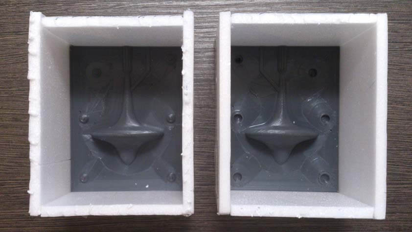
In order to cast my molds I needed to make a box around them to contain the casting materials. I made a box out of acryclic by using the laser cutting machine.
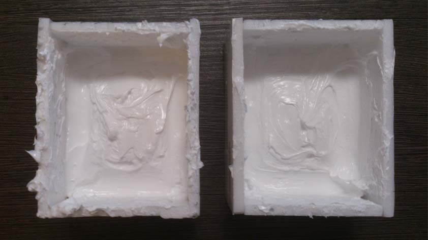
▸ Casting Mold Max 29NV
As I plan to cast Cerrotru I started to cast the Mold Max 29NV material which is a rubber resisting to temperatures up to 204°C or 400°F. The cerrotru melting point is 138°C, or 280°F .
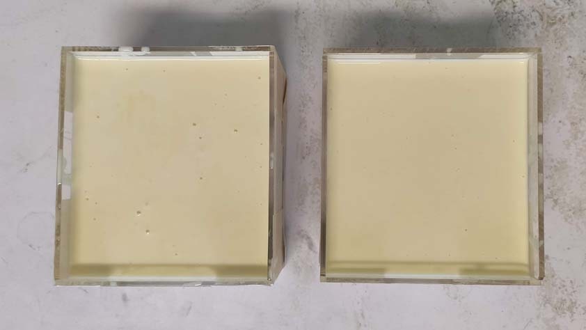
Here is the molds casted with the Mold Max 29NV. A lot of air bubbles appeared when pouring the mix, the data sheet specifies that there is no need to put it in a vacuum chamber, so I poured it and let it be.
Here is a video of the pouring process. Material is hard to pull off the container at the end, more than the falf of the video at the end is me trying to catch the mixture left in the cup.
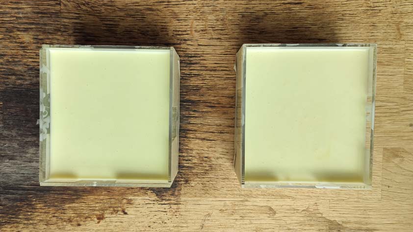
And here is a picture of the rubber that has dry for 12h (6 hours only are needed), bubbles disappeared or became very tiny.
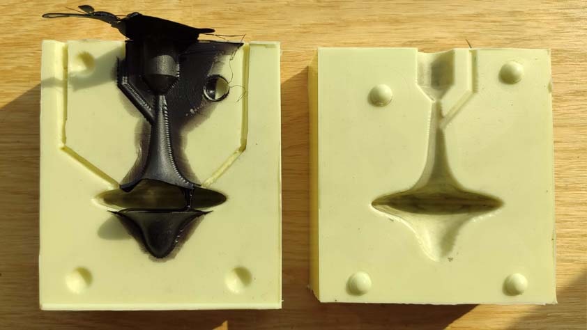
▸ Casting Cerrotru
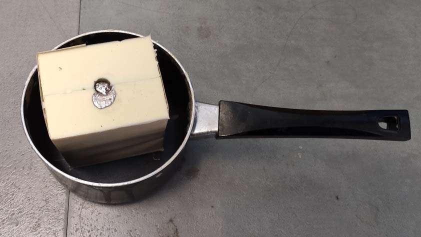
Cerrotru is Eutectic Alloy, its melting point is 138° so it possible to melt it by using a kitchen torch. It is presented as a bar of metal, and has to be cut before use.
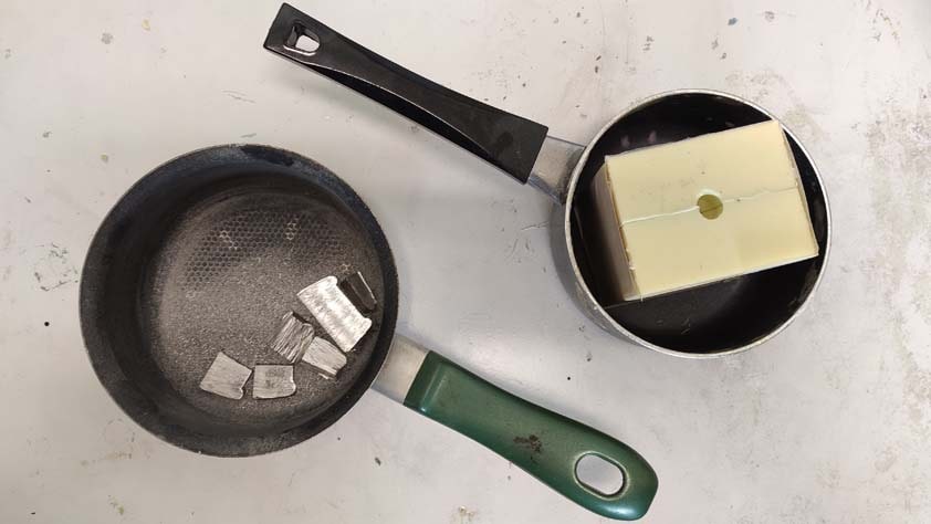
Ambroise helped me a lot during this process, and here are the tools and material we used :
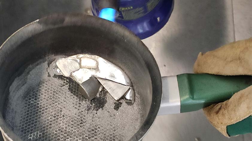
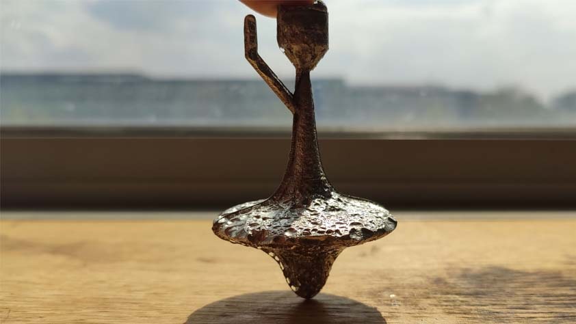
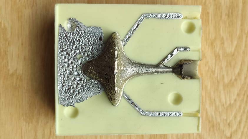
The kitchen torch is used to heat up the cerrotru in the pan, it becomes a liquid and the pot life can't be very high so hurry up to pour it in the rubber mold (with a lot of care, it's 138°C at least in the pan). The viscosity of this melted eutectic alloy is surprisingly thinner than I expected, which is great because I designed the pouring hole and air pipes too thin.
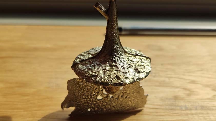
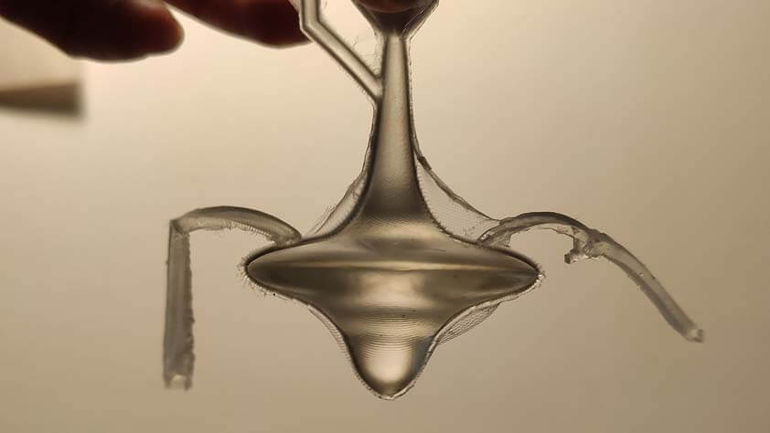
I waited for half an hour to demold the cerrotru cast, I waited for it to cool down so it is safe to remove it. The first result is awesome, but so much bubbles were not expected. I knew my pipes might be too thin and probably not very well positionned for their job, I placed them were they wouldn't hurt the final shape too much (as it is a spinning top, it has to actually spin). But now I realise that designing the pouring hole on the other side of the molds might have given better results, the post process would have been longer in order to model the point of the spinning top. I still have to polish the molding marks.
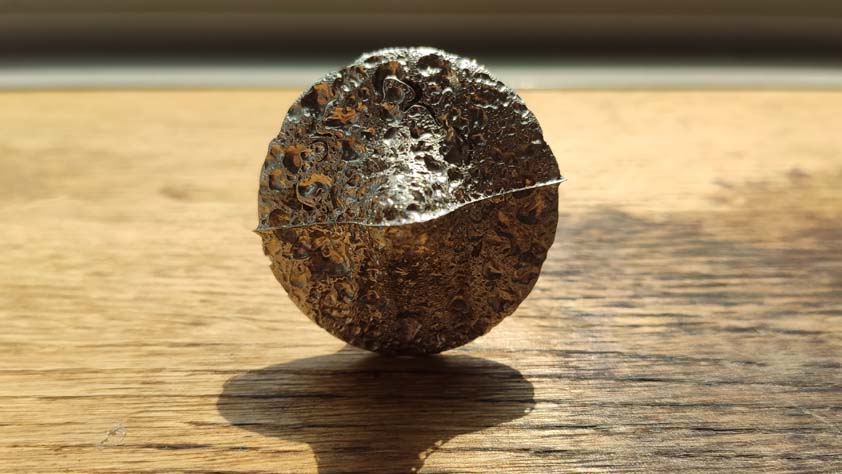
The final object is pretty heavy for its size, here it is spinning :
And here is an alternative link to the video file
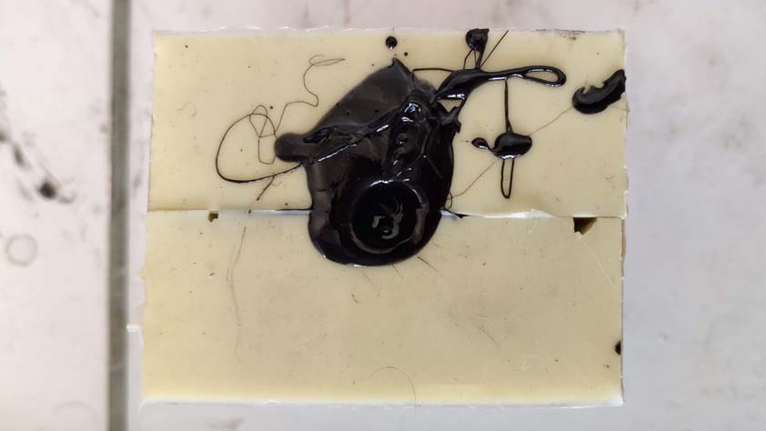
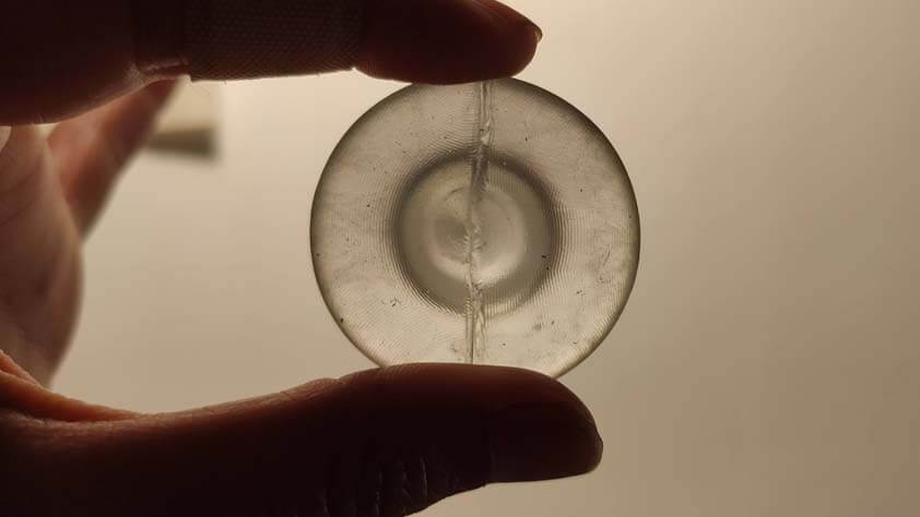
I decided to add air pipes by cutting the rubber with a cutter and to recast the Cerrotru. it doesn't change anything regarding the amount of bubbles, and I pressed the mold too much when taping it, it created space for the cerrotru to go between the molds.
The second try is also yellow coloured because we used a stick of wood to stir the cerrotru when heating it up. We thought it would be great to use the powder created when sawing the bar, but it actually didn't melt very well in the pan.
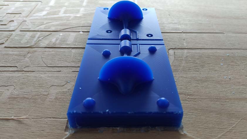
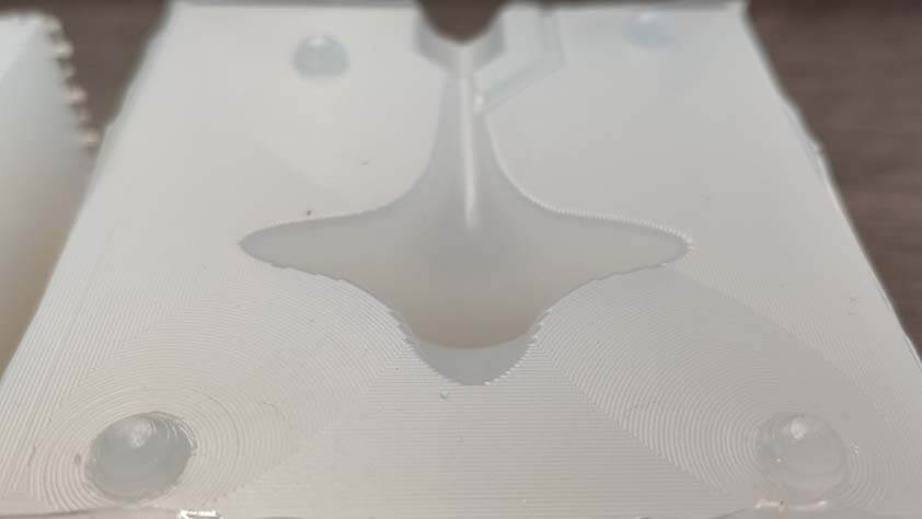
▸ Casting Ecoflex 00-30
Here is another test using the Ecoflex 00-30 very soft rubber which is a skin safe material.
The Ecoflex 00-30 seems to grasp more details from the milling process than the Mold Max 29NV.
I demolded the mold of mold and prepared it to pour the Gedeo Pebeo resin I have at home. Waiting for 24 hours, result on wednesday evening.
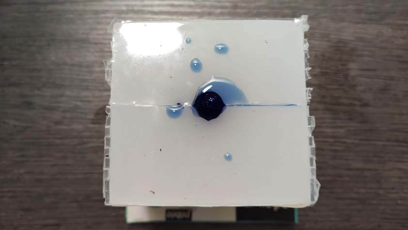
I poured the gedeo resin and it produced a lot of bubbles in the mold. I poured some resin in a cup, this one didn't produced bubbles at all, so this might be related, again, to the size of the pouring hole of the mold.
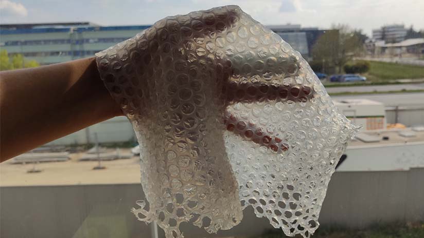
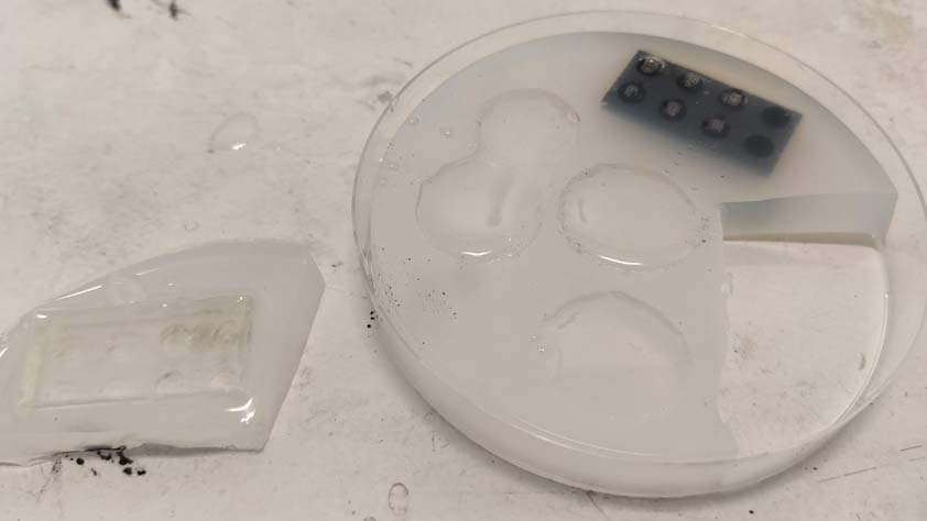
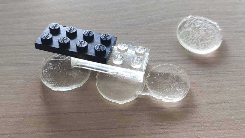
I made way too much of this product because I didn't realised the weighting machine was not weighting properly. So I had a ton of Ecoflex and no molds to cast it in. I poured it on bubble-paper, here is the result, it is elastic and also stick very well to glass.
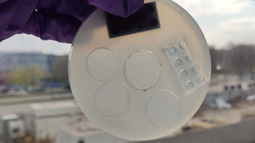
We also poured it into a recipient with coins and lego that Ambroise brought, so now we can make money and legos. (almost). We poured epoxy resin in it_ but the result will be discoverable on thursday.
▸ Casting Onyx Fast
I tried to cast the liquid plastic Onyx Fast in my molds, but the mix was really dense and my pouring hole being too thin, it didn't go through very well, and as it has a 2.5 minutes pot life, it dried super fast. Here is the hollow not spinning top.
to get a better result I would have to modify the diameter of my pouring hole, or to be faster.
▸ Epoxy Resin Super sap
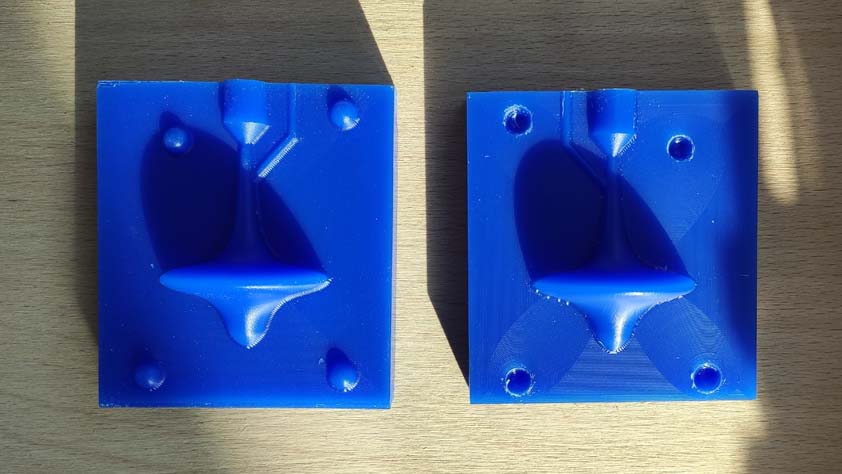
Here is another test using the Epoxy Resin Super sap, poured in the Mold Max 29NV molds. The cure time is specified to be 4 hours, but the recommended drying time is 7 days. It depends probably on the type of casting job. In my case, after 10 hours of cure time, the resin's surface has dried, but the spinning top is stil very flexible.
The milling traces details are well engraved on the surface of the resin. As well as the colour of the previous cast.
☛ Other test with 3D printed molds
▸ Bathroom silicone
I wanted to try the molding and casting process with 3D printed parts, so I 3D printed my molds, made a box around it and put (instead of pour) bathroom silicone in it. I did it on saturday evening, it's tuesday and still, it has not dried yet.
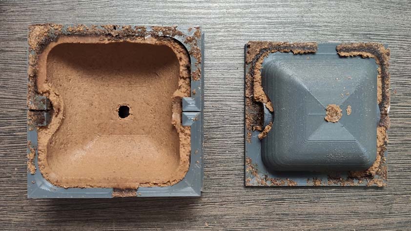
▸ Molds for compressing composites
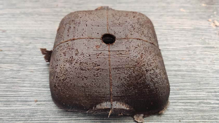
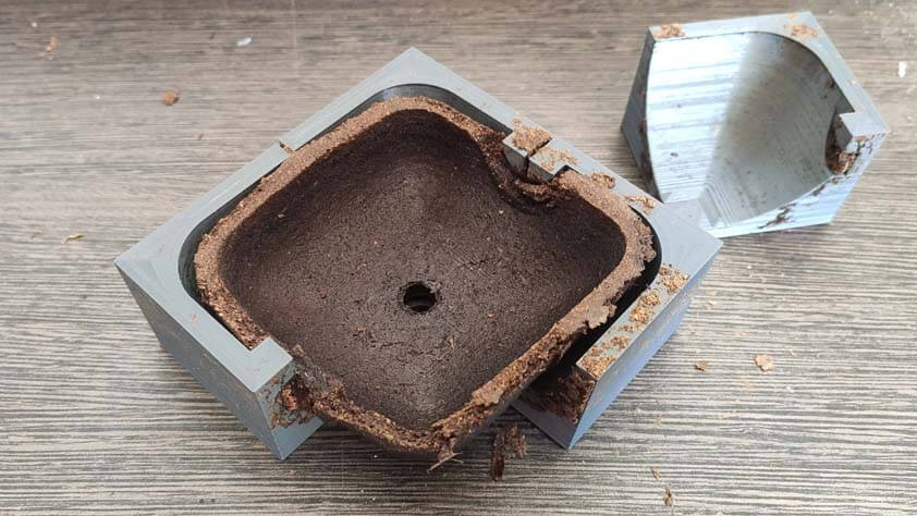
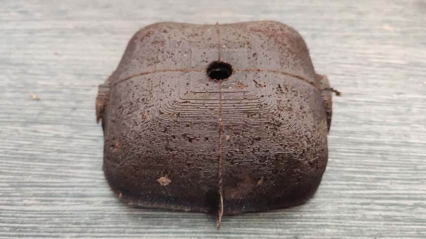
Before I realised this week was about 3D milling, I wanted to make molds for my final project, they are complex and I'd rather print them to test them instead of milling them right away. I would like to make most of my final project parts from composites materials (a mix of sawdust and casein glue that I documented here during the Pre-Fab Academy).
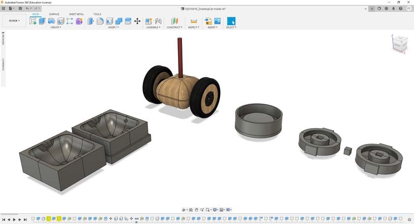
Here is my first test for the body of the drawing car in the sreenshot above.
The process then is to prepare the casein glue, which is made of milk, vinegar and baking soda, to prepare the sawdust, from walnut wood in this case, I make it pass through a colander to use the thinner part of it, and mix both to obtain a desnse clay.
The clay is placed into the molds, in the edges first, and in all the mold, then it is pressed.
After 24h of drying in the mold, it has to be open in order to prevent the mix from rotting in it. Then the next step is to wait for it to dry before demolding it completely.
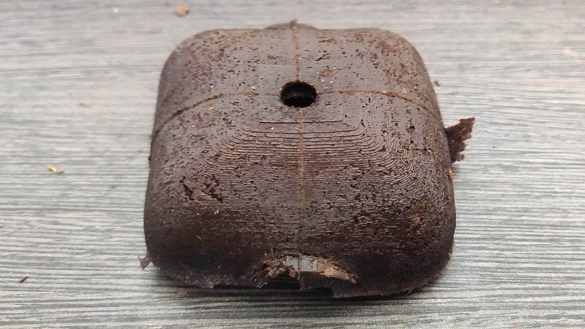
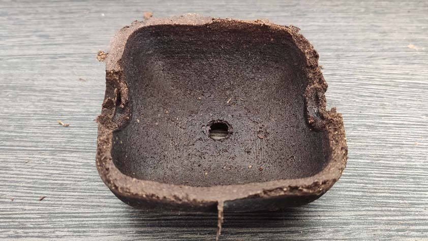
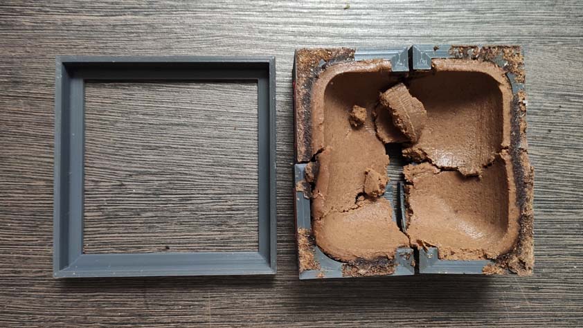
Here is the first demolding test. My error was to be impatient, and to take out the squared ring maintaining the mold when opening it up after 24 hours. At this point I should have let it open and wait for it to dry more before trying to see what it looked like.
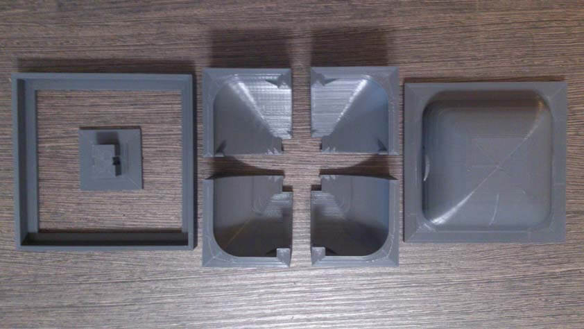
The second part of the body went a little bit better, but the mold has to be modified as important junctions parts of the final piece are too damaged to be useful.
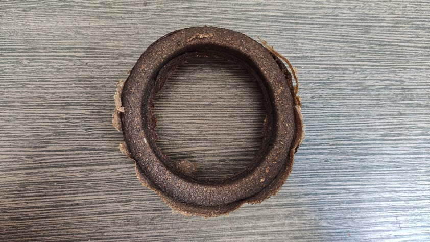
Here is a 3D printed mold for the tyres of the car. It is printed in flexible TPU. It's a first try, and it seems easier to use as it is flexible - the issue might be the risk of deformation as it is pressed.
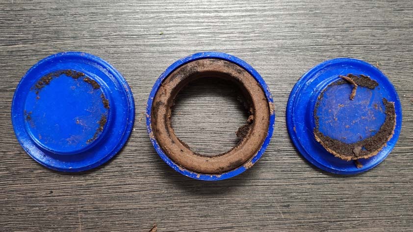
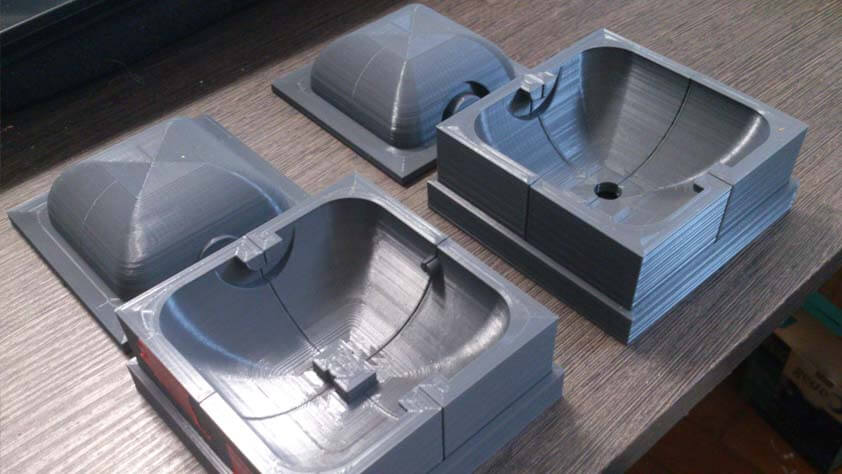
Opening the mold + 36 hours later : here are the demolded parts.
The tyre got deformed, and the junctions details are too damaged, the mold should get some modifications in order to divide it in smoother shapes.
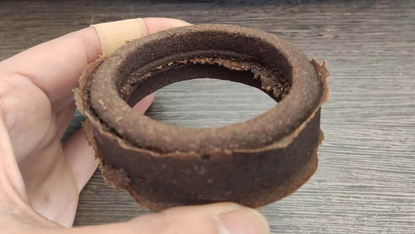
The body part got deformed as well, I think the mixed composite had too much water in in when I put it in the mold, and that evaporation is causing this - but I can't be sure. Here again I will simplify the mold shapes so it is easier to demold without damaging it. I could also print a thinner mold with holes, to replace the first mold when it has to be removed. This might be useful in order to maintain the shape of the final piece while it has to be opened to dry.