The Plan
I had a grand plan to combine several different boards and create a game of telephone between my phone sending a message over bluetooth serial into an esp32 and then connecting to an attiny and then a SAMD and then serial into my computer. I had hoped to have the message get modified slightly on every hop along the way. This plan did not survive first contact with reality.
Bluetooth
I have an esp32 devboard and installed the esp32 arduino board library. I downloaded the serialToSerialBT example program and a bluetooth serial test app to my phone and was able to connect the two and whatever I typed on my phone was repeated over the serial monitor onto my laptop and vice versa. I didn’t have time to mill my own esp32 board so that is where I left bluetooth for now.
I2C and Serial
I wanted to try to connect two boards with I2C and though it would be a good protocol to communicate between different architectures. I wanted to also expose serial lines as a back up incase I2C was harder than I expected. I had planned to make an Attiny based board and an SAMD based board to get them both talking. I made the Attiny board but had some problems that slowed me down so the SAMD board hasn’t happened yet.
Attiny Board Design
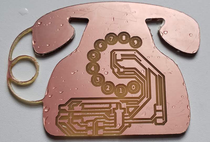
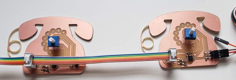
I setup a simple schematic for an Attiny412 board that had headers for updi, power, and ground, an another header for SDA, SCL, TX, RX, power and ground. This would pass I2C, serial, and power between linked boards. I also wanted to play a bit with circuit board art because I’ve been jealous of all the interesting looking boards other people in fab academy have been making. I decided since my boards were going to play a game of telephone the board should look like a rotary phone. I had one extra pin so I added a rotary potentiometer as an input that could be used for some added fun if everything else works.
Circuit Design
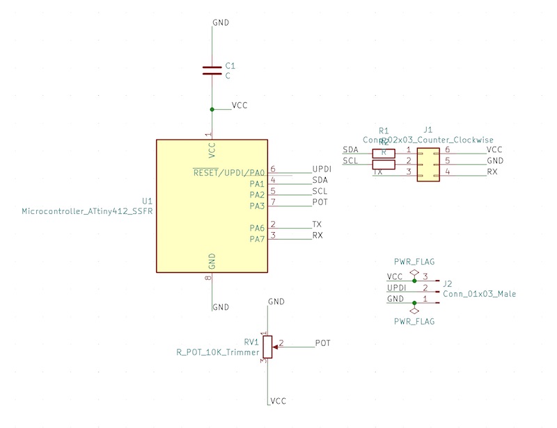
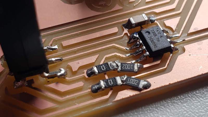
The circuit design for I2C is the only new peripheral for this board. I2C uses 2 pins a data pin SDA and a clock pin SCL. The recommendation is to use 10K pull up resistors between these lines and VCC to hold the line high when not driven. I messed this up and just put these resistors in the line instead of as pull ups but I didn’t want to mill new boards again so I just bodged in some jumpers and 0 ohm resistors where I had mistakenly specified them. I’ve fixed the board design for future iterations.
Board Art
I found some phone clip art online and converted that into a vector graphic with inkscape. I simplified the graphic to just the outline and the numbered circles. I imported the outline as and edge cut layer and the numbered circles as a user drawings layer in kiCAD. I spent too much time trying to route the connectors for updi and communication to sit on the actual telephone speaker and microphone but decided the board was already bigger than it needed to be so I just put them down in the base. I did put the potentiometer right in the center of the numbers incase I had time to add a dial or pointer to select a number (I didn’t).
Milling and Populating
I had ordered some new tapered stub end mills suggested by Dan Meyer. These are great because they are more robust than the 1/32" stub end mill I had been using and can run at much higher speed without breaking. The problem is that I got 0.0150 tipped end mills but they are a 15 degree V bit so at a 0.002" depth of cut they are actually 0.017" which is just a bit wider than the 0.4mm. This meant that when I ran the layout through mods with this size bit some of the traces were too close together and my first iteration of the board had a bunch of merged traces. I re routed the board increasing the track clearance to 0.44mm and re milled it. I made two boards. One still had a few traces too close together so I fixed that with a razor blade.
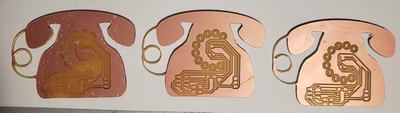
I also realized at this point my mistake about I2C resistors that were supposed to be pull up resistors so I bridged some extra copper to ground and moving the pull up resistors to those bridged copper pads. I placed 0 ohm resistors where I had originally placed them. I modified the board layout to fix this if I need to build more.
I2C Code
At this point I wanted to test these boards before I moved on to make the SAMD board. It was at this point when I realized that I2C probably wasn’t the right protocol for this project. Sparkfun has some good tutorial information. There is also some good info and example code with the Arduino Wire library. Sparkfun has a good note on terminology for I2C, “You may be familiar with the terms “master” and “slave” to represent the relationship between devices on an I2C bus. The terms are considered obsolete and are now replaced with the terms “controller” and “peripheral,” respectively.” I will try to use the controller/peripheral terminology but the Arduino example code still uses the outdated terms.
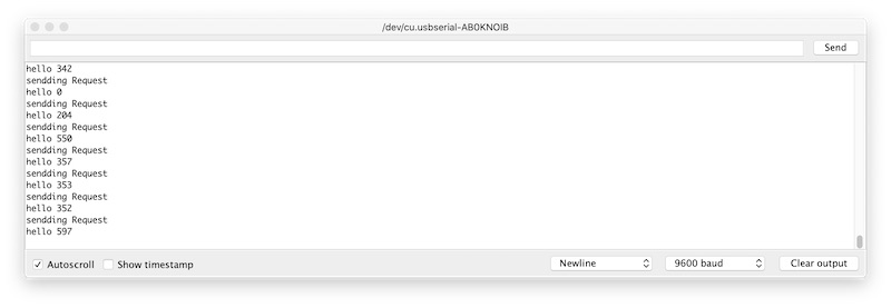
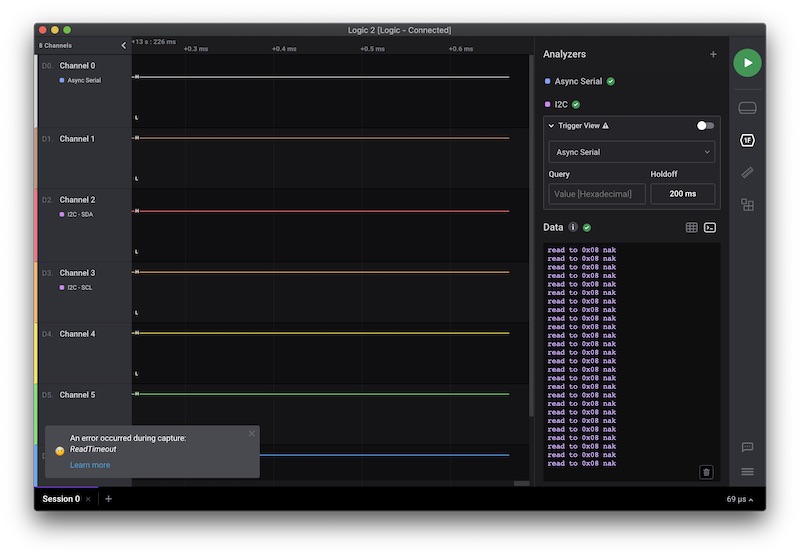
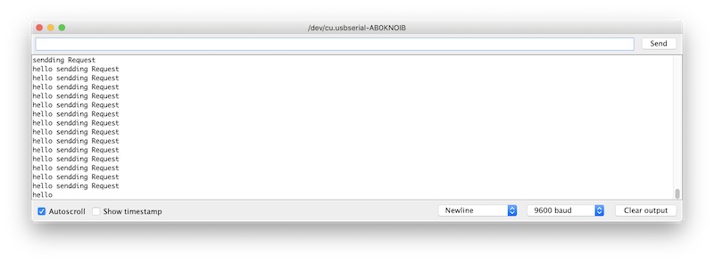
I loaded up the Arduino examples for a reader/writer and loaded one of each onto my boards. I added some serial output to confirm things were running and each board seemed to work fine on it’s own but they wouldn’t talk to each other. I loaded the controller code onto both boards so they would send data. I took out my logic analyzer and plugged into each end’s I2C pins to see where the missing link was. One board looked good but I wasn’t getting anything from the other. I took out my multimeter and found a cold solder joint on one of the I2C lines. Fixed that joint and then it looked good. I put the peripheral code back on one board and they started talking.
I then wasted a lot of time trying to remember how to deal with byte arrays in C to send the value of the potentiometer back across the I2C lines as a set number of bytes. I couldn’t get it working. I don’t miss statically typed languages. I need to setup a board that can run microPython.