Plan and Board Design
My plan for this week is two fold. First I want to figure out why my RGB LED didn’t work during embedded programming week and fix that. Second I also want to control a motor. I’ve got a small pager motor and a larger DC motor. I’m going to start with the circuit I designed for the embedded programming week using the samd11 chip because it has a few extra pins that I can use for an H-bridge motor driver.
I started by looking at the old circuit and the data sheet for the RGB LED. I figured out that I had swapped anode and cathode and had connected the common pin to ground and it should have been connected to power. That was an easy change in the circuit design.
I looked at the reference design in the data sheet for the A4953 H-bridge motor driver. It was pretty simple and included a pair of capacitors to smooth the high voltage power side. I decided to be lazy and omit those since I’d be connecting to a bench power supply I wasn’t too worried about power fluctuations.
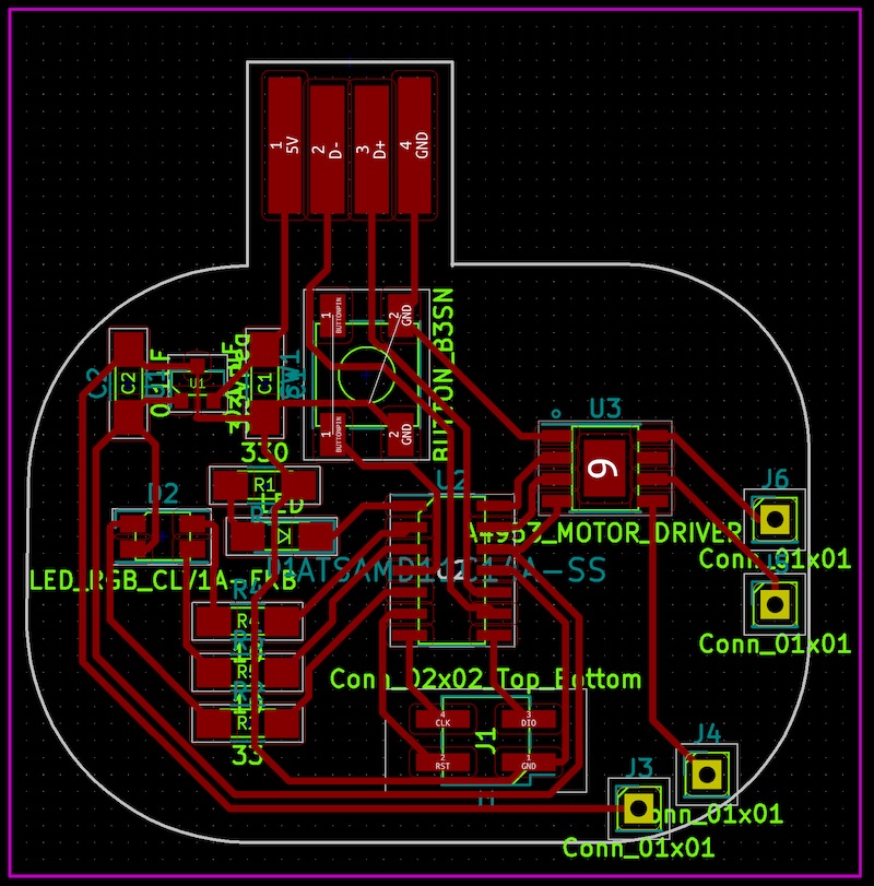
Board Layout
With some minor adjustments to the schematic I laid out the new board. I made a few adjustments to the circuit path. I tried to be tricky and route the ground through the button so I didn’t have to loop all the way around the board. It turned out I wasn’t paying close attention and made some simple mistakes in the layout but it was close enough. I milled the board which had a minor problem. The z height was inconsistent on my mill because the piece of FR1 has been stuck down to it for nearly two months with the same double stick tape and that’s starting to give way. I adjusted the z height and stuck the tape back down and it milled fine.
Population Problems
Zero to Code
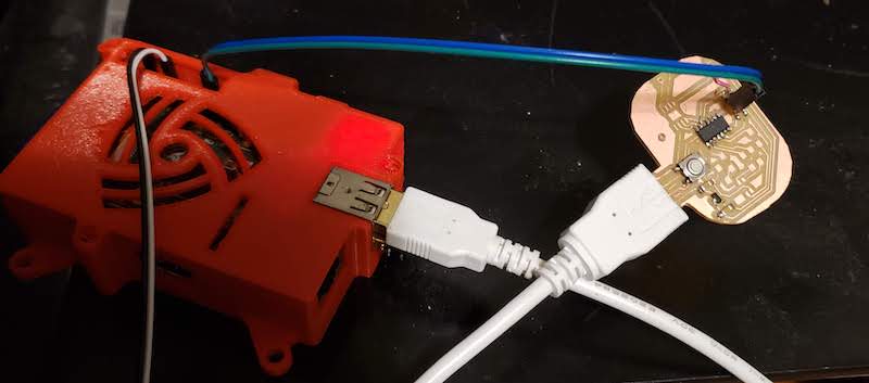
I wanted to take my time populating the board to test one subsystem at a time. I started with the IC, and power system, and programming headers.

I tried to program the board just to make sure everything was working up to this point and I identified my first problem immediately. I had routed the ground to the voltage regulator through the button so I needed to install that before I could get 3.3V to the IC.

So I installed the button and the regulator now had the correct output voltage but power wasn’t getting to the IC. I took a closer look at the layout and found that I had connected the ground on the IC to the programming header and the motor driver but it wasn’t connected to the USB ground anywhere. I added a patch wire to fix this. Now I could program the board using my raspberry Pi setup from embedded programming week. I went back and updated the board layout to fix this if I had to make another.
RGB LED
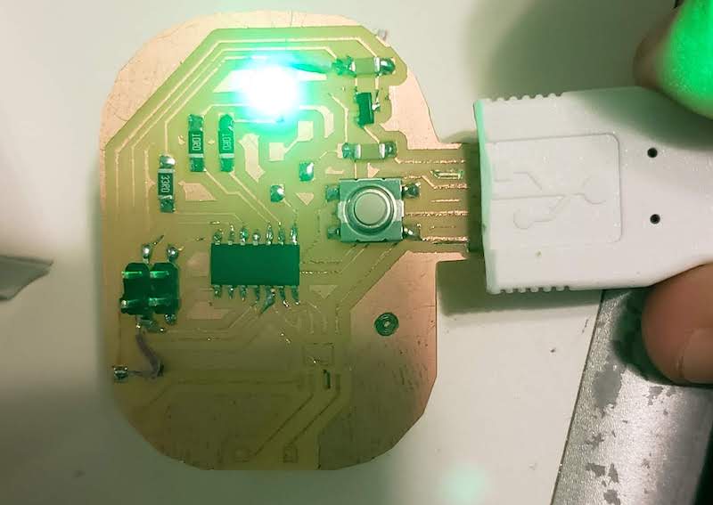
Next I wanted to get the RGB LED working. I had some test code from my previous attempts at an earlier version of this board. I added the 3 resistors and the LED. I used this LED resistor calculator which took into account the voltage drop across the LED and found that the resistors I was using in the old board were much larger than I needed. I also hadn’t yet realized that I had the common anode connected to ground instead of 3.3V. I cut the ground trace and added another patch wire and updated the layout again to address this change.
After the fix and some new code I was able to get the LED to light up in all three colors and use PWM to do some simple color mixing. I started with the Arduino fade example for a single LED and created a random starting value for each LED and faded it from there.
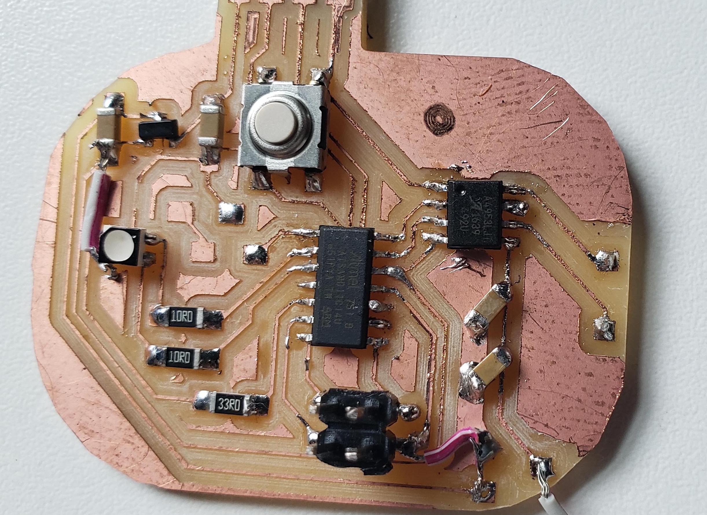
Motor Driver
Next I wanted to get the motor driver chip installed and see what motors I could run. I had a small pager motor. I had removed the eccentric weight so it’s just a small DC motor. I don’t have any specs on this motor but I looked at some similar motors that said they could be run from 1.5-5V. I also had a larger DC motor that I had no specs for but I’ve run similar motors from 5-12V no problem. I started with the smaller motor. I had included some extra pads for the motor output and the high voltage input. I put 5V into the VBB pin of the motor driver from my bench power supply and added some code that should have turned the motor on and off. I didn’t work. I’m still not quite sure why. I poked around with a bunch of different code and fiddled with different connections for the motor and supply voltage. I never got the motor to turn on. I probed the pins from the IC to the driver and could see that they were turning on but the motor never reacted.
I could directly apply 5V to the motor and that worked fine. I though I had read the motor driver’s input voltage was 2-40V so I though I was well inside its working range but nothing worked. I’ve since heard an of hand comment from Neil that it’s minimum voltage is 8V. The first page of the data sheet just lists the maximum voltage of 40V. I scrolled down more and now see that there is a larger chart with minimum of 8V. That would explain a lot of my problems. Still doesn’t explain the intermittent behavior at higher voltages.
Another Approach
I wanted to sanity check my circuit and driver so I downloaded Adrian Torres’ Motor driver breakout board for his Adrianino. I milled and populated that board and hooked it up to an Arduino Uno just to make sure my driver board worked and it wasn’t something dumb in my code that was the problem.

The setup was kind of janky and my desk is a huge mess but it did tell me one useful thing. I tried hooking up the larger DC motor because the smaller one was soldered to my other board and at 5V that motor didn’t response either. I’m not sure where I got the idea but I just decided to crank up the voltage on the power supply. I turned it from 5v to 10V and it started working. The code I use should have run the motor and turned on the Uno’s on board LED for 1 second and then stopped the motor and turned off the LED for another second. It mostly just blipped the motor on for less than a second, the LED would stay on, and then turn off. Then the LED would turn back on and the motor would blip again but not spin for a whole second. I messed with the connections for the motor and power supply and some times I could get it to run for the full second and then sometimes it would just keep running and not turn off.

While I was at it I checked the current of the motor by reading the output of the power supply. When the motor was running at 10V is used about 0.2A at no load on the motor.
I noted two differences between Adrian’s board and mine. He had the capacitors suggested in the data sheet. I still didn’t populate them to compare with my other board. It sorta worked so maybe adding them would fix the intermittent problems. He also had ground connected to the thermal pad under the chip and the LSS sensor output pin. Since this still at least sort of worked without the capacitors I decided to bridge those two ground connections and see if that helps.
Back on Track?
I bridged those ground connections and switched to the larger motor. I turned the power supply up to 12V and tested the same code I was using before. It also worked sporadically. And then stopped working again. I’d guess maybe I’m hitting a thermal protection in the driver. I’m not really sure. It could still be that I really need to install those filter capacitors and that will solve all my problems.

Stop Cutting Corners
I added in the filter capacitors to Adrian’s board and everything works fine with my Arduino Uno setup. Maybe I shouldn’t have thought I was more clever than the chip designers and everything would be ok. Now I have to add them to my board somehow and see if that works.
I added capacitors hacked onto my board but didn’t have success getting the 12V motor to work.
Restart
I designed a new board using Adrian’s board as a guide for the motor driver circuit and based it on an ATtiny412 because I’m more comfortable with the workflow for that chip. This worked fine. I think I had damaged the motor driver on the old board because of all the patches and workarounds. This board worked no problem with a new motor driver chip.
Design Files
SAMD board
ATtiny 412 board
Code
The same code tested on all the boards.