7. Electronics design
Group Assignment
Again, I am completing most of these week’s group assignment independently here in Maine. For reference, here is a link to Charlotte Latin’s group assignment for this week.
Electronics Measurement Instruments
Multimeter
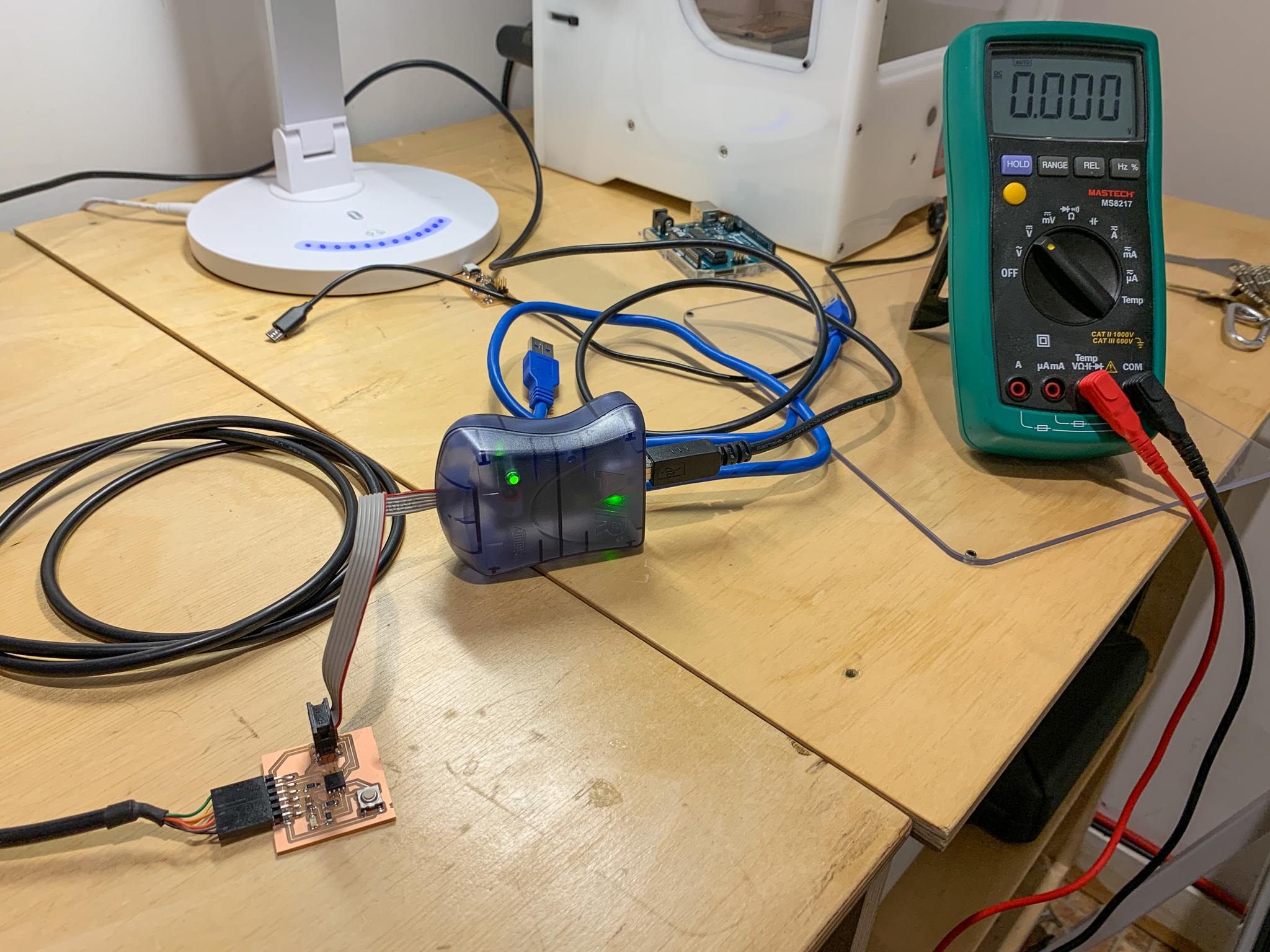
Multimeters are probably the most commonly used measuring instrument in the field of electronics. They are the swiss-army knife equivalent when troubleshooting circuit boards. Most importantly, they can measure resistance, voltage, current, and continuity within a circuit. In my case, I use the multimeter for measuring operating voltages to make sure the microcontroller is receiving the correct voltage from the power supply (i.e. 5 Volts DC or 5VDC), and detecting short- and open-circuits using the continuity test setting. This setting is handy because you can use the two probes and touch any two parts of a circuit and quickly get feedback. If the multimeter makes an audible tone or sound, then it indicates that there is a short-circuit or continuity between those two points in the circuit. Sometimes this indicates a correct solder joint, or proper connections throughout the circuit, and other times it can indicate something bad has happened in the milling or soldering process. With a schematic handy, you can probe around your circuit and make sure everything is connected as it should be.
Oscilloscope
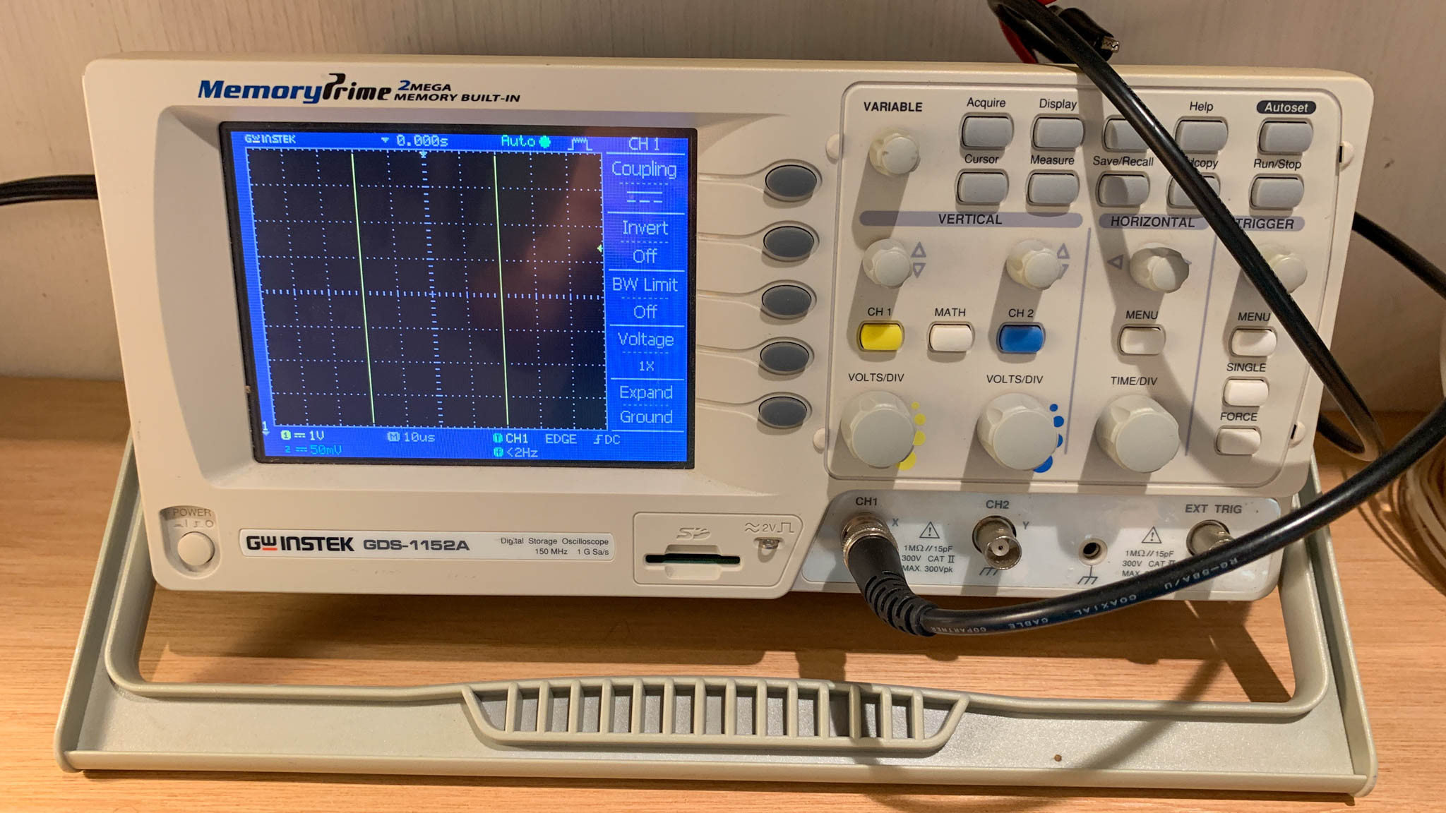
I ended up using the oscilloscope to test the voltage, in a similar way to the multimeter. I know this is not a great illustration of why one would need to use a scope, but I have not come across a situation where I need to monitor the signal (yet). If I end up using the scope in a more useful way for my final project, I’ll update this section here.
Designing an Electronic Circuit Board
Okay, so I decided to try and start small, by designing a simple circuit (button + LED) using the ATtiny45. I like the idea of being able to make many small embedded controllers, and I especially think these small boards will come in handy for my final project. So, onto to the design.
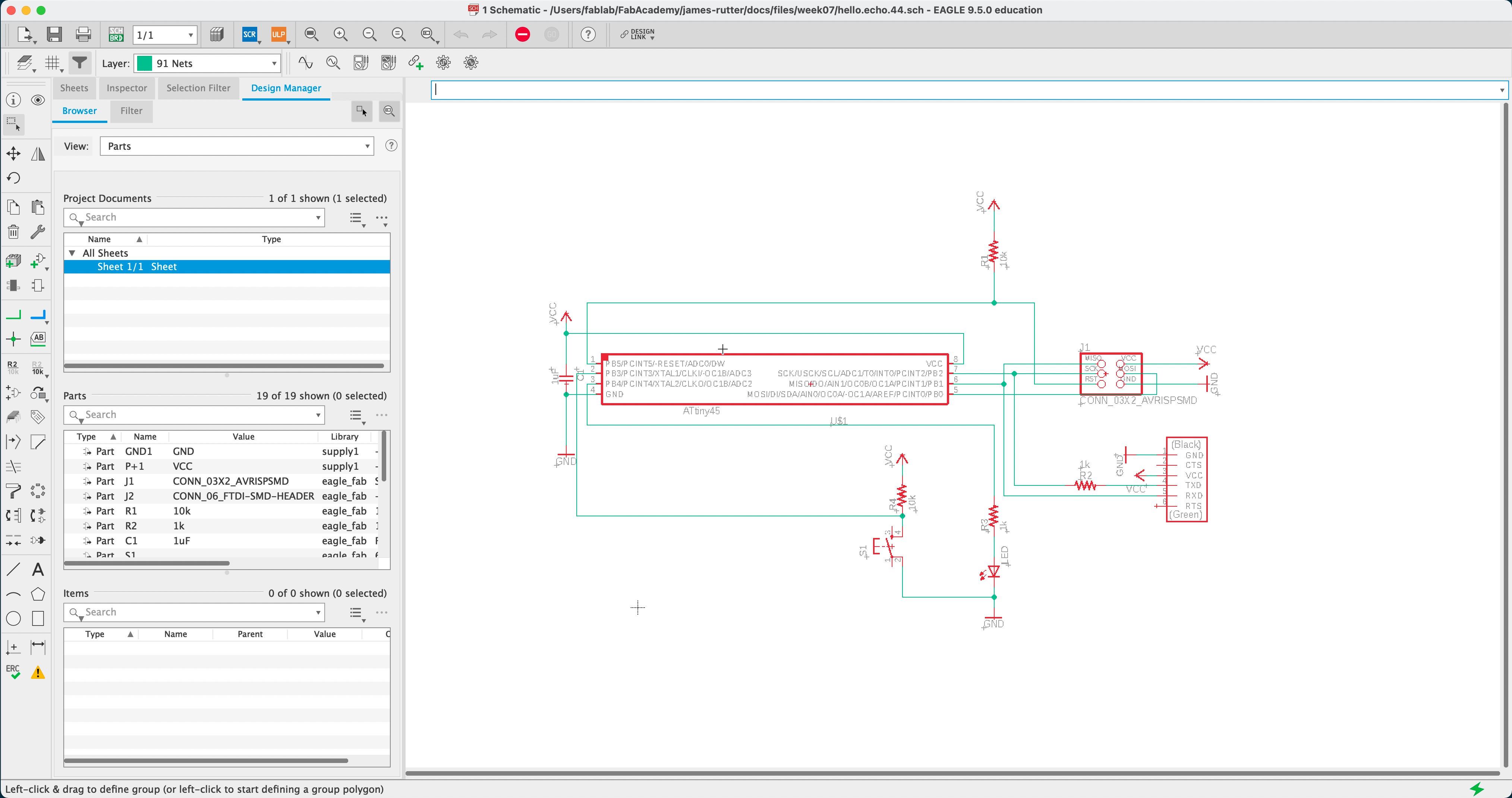
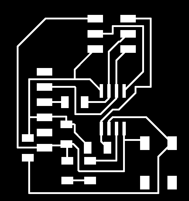
I decided to use Eagle since that is the program I learned in college (way back when) and I have used it several times over the years so I was able to jump back in and design the schematic fairly quickly. I did however use the ATtiny44 first and didn’t realize this until I switched to the Board layout Mode in Eagle. I switched the components out in Eagle, which doesn’t take too long. Much faster than having to re-mill, stuff, and solder a board.
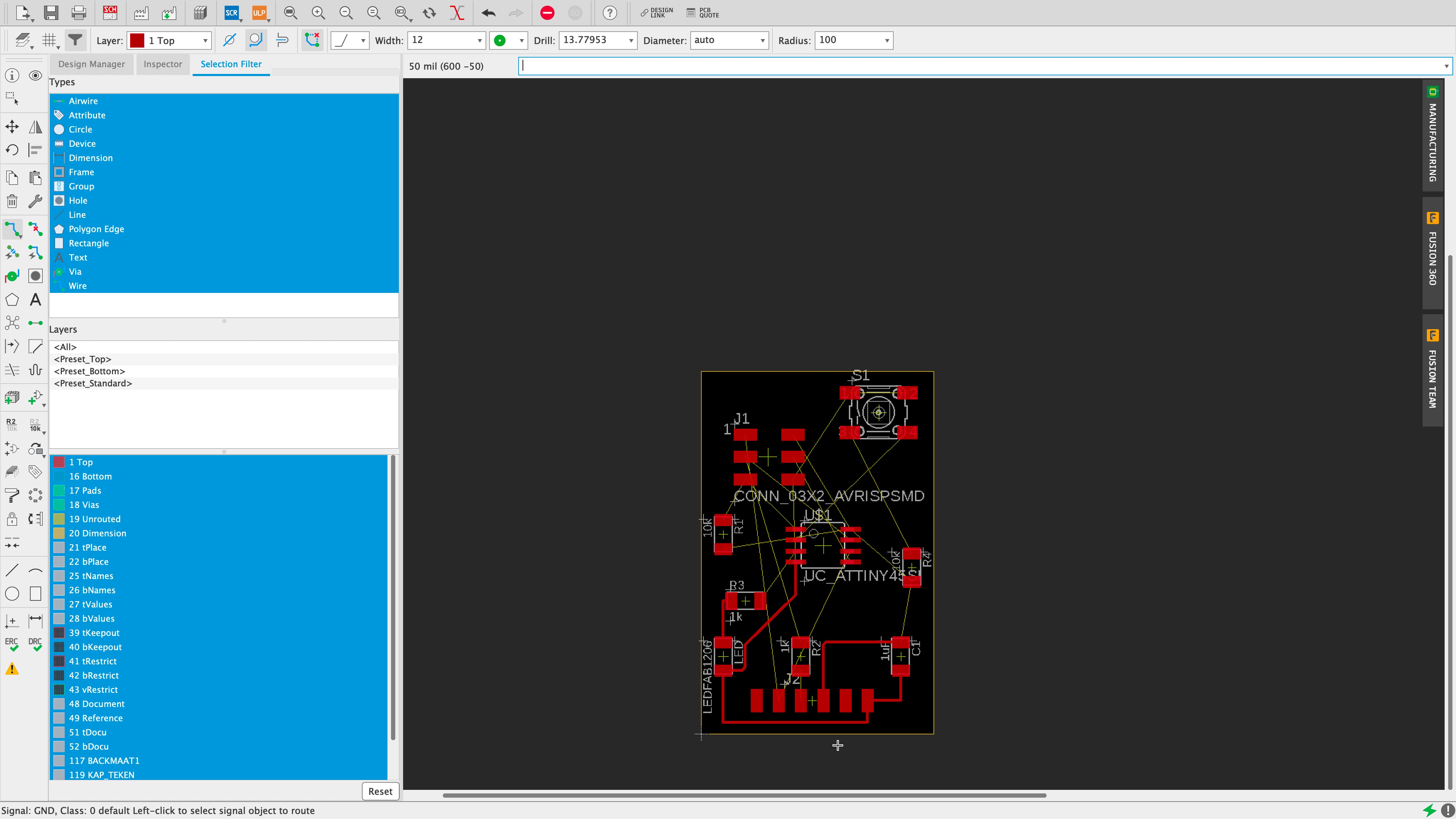
Drawing schematics is easy and straight forward, it tends to be a dull task. Laying a board out and routing the traces is a puzzle. It is a fun problem to solve and can take a while but it is rewarding when you finally figure out the best way to route a board without having to use any 0-ohm resistors to jump over traces (not that there is anything wrong with that).
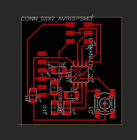
It took me about 90 minutes, and I had to re-learn some of the tricks in Eagle to get precise control over the ROUTE tool, but I was pretty happy that I got a board layout with a button + LED on the ATtiny45 without any jumpers needed.
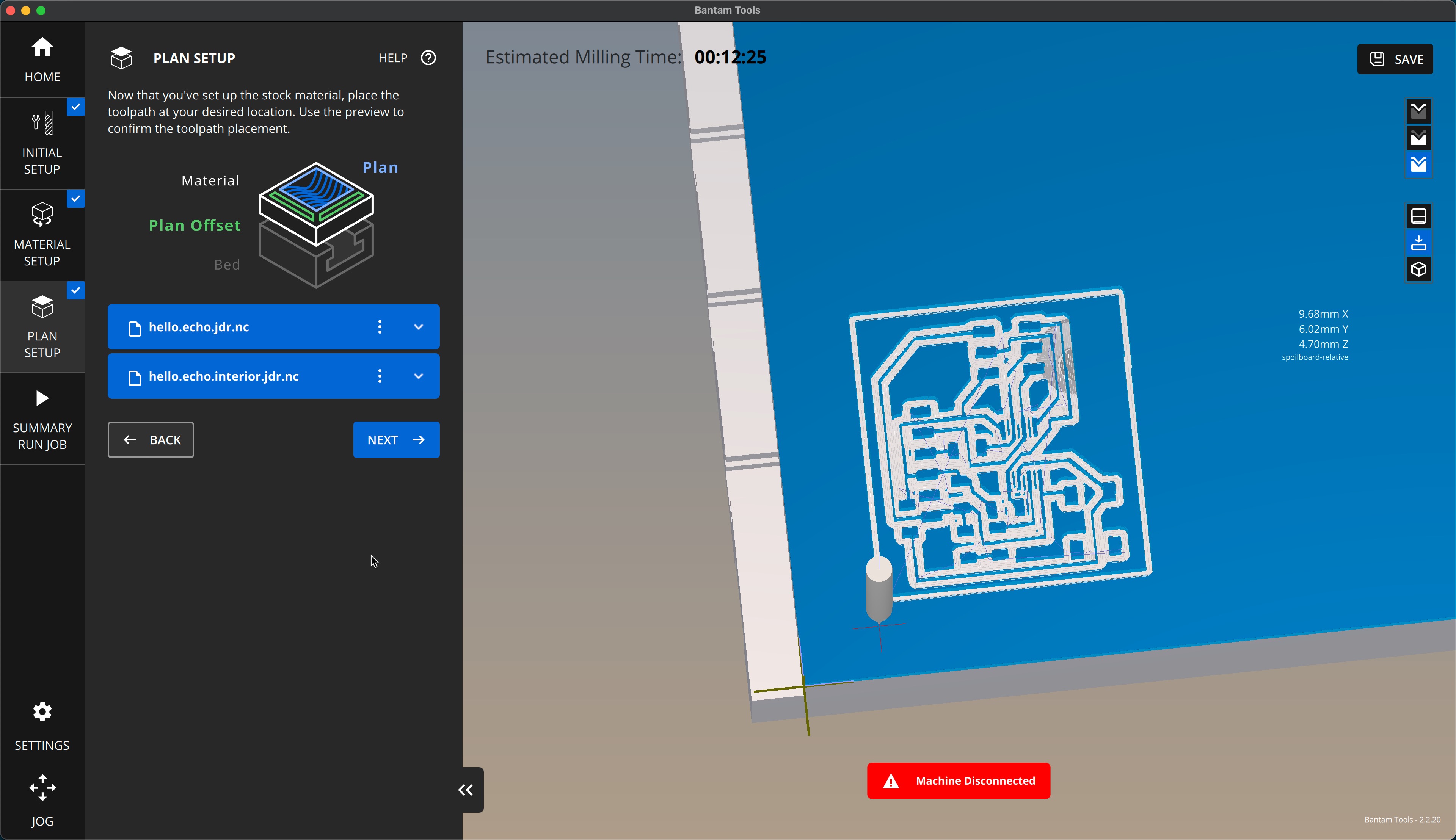
Onto BantamTools. Apparently, Bantam updated their software so I am using the new version of their software. It takes some getting used to but I finally figured out how to go from the PNG exported out of eagle, to the Fab Mods, and then from the NC file exported from the Fab Mods into BantamTools. That is the workflow or toolchain to get from Eagle to the milling process. It is a little cumbersome, but it works.
Fabricating and Soldering
Milling out the board game me some trouble.
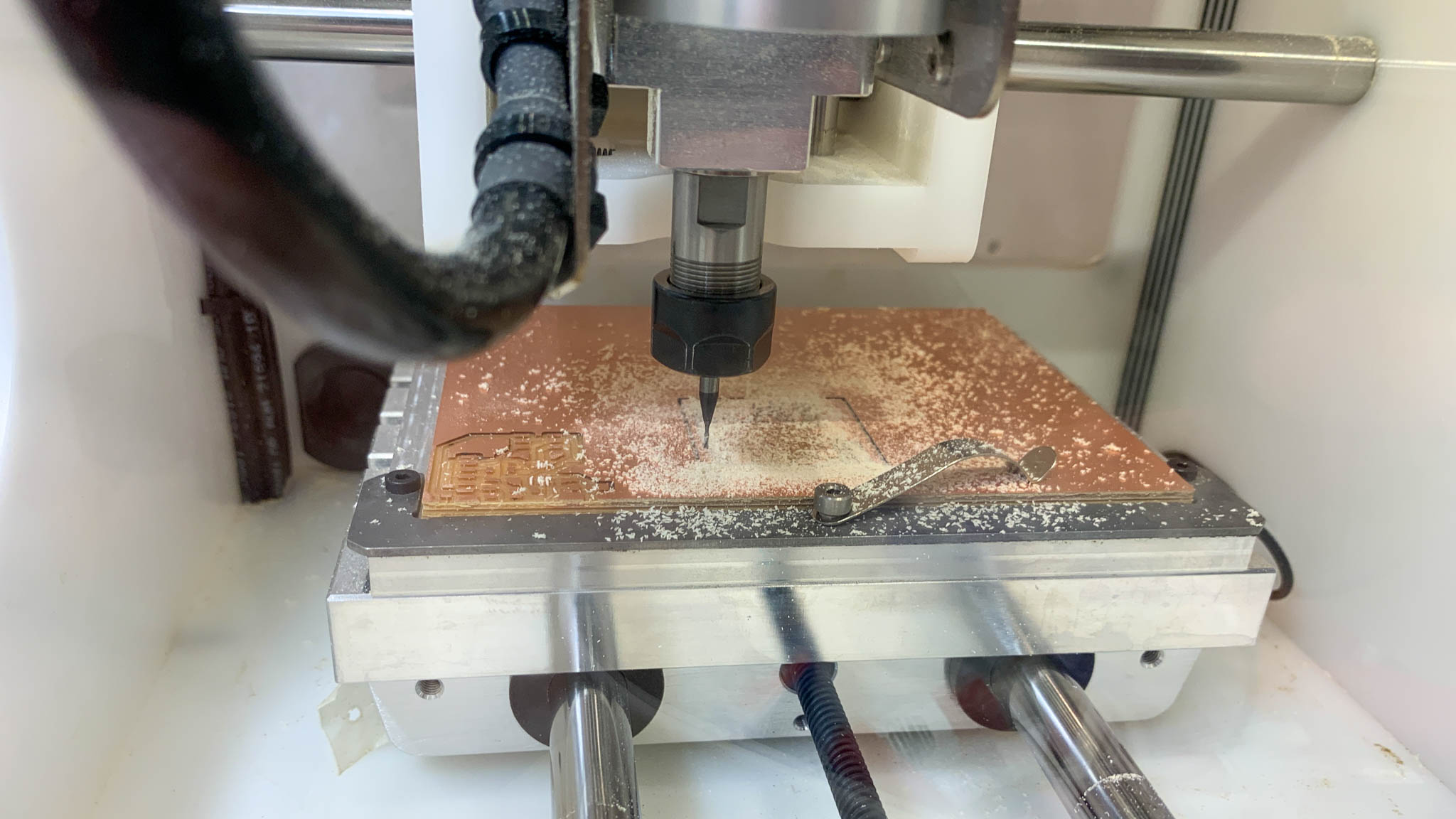
I accidentally rip off a trace on my first try so I had to re-mill the board. I am also a little concerned that I made the traces too thin (12mil), so we’ll see if it holds up and works.
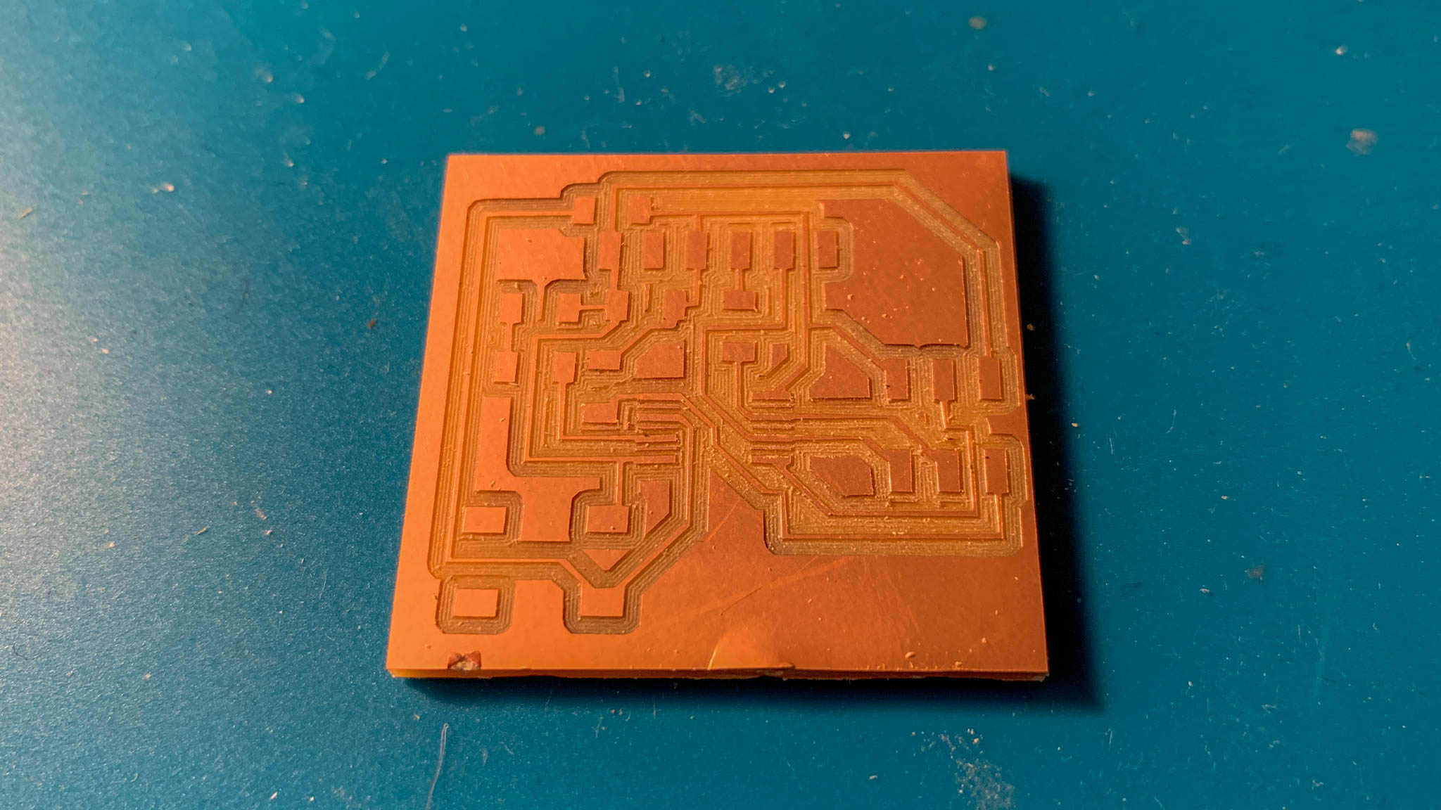
The board came out okay once I used the proper tool to extract it out of the machine. I ended up using a sharp pocket knife to pry the board off the double-sided tape layer.
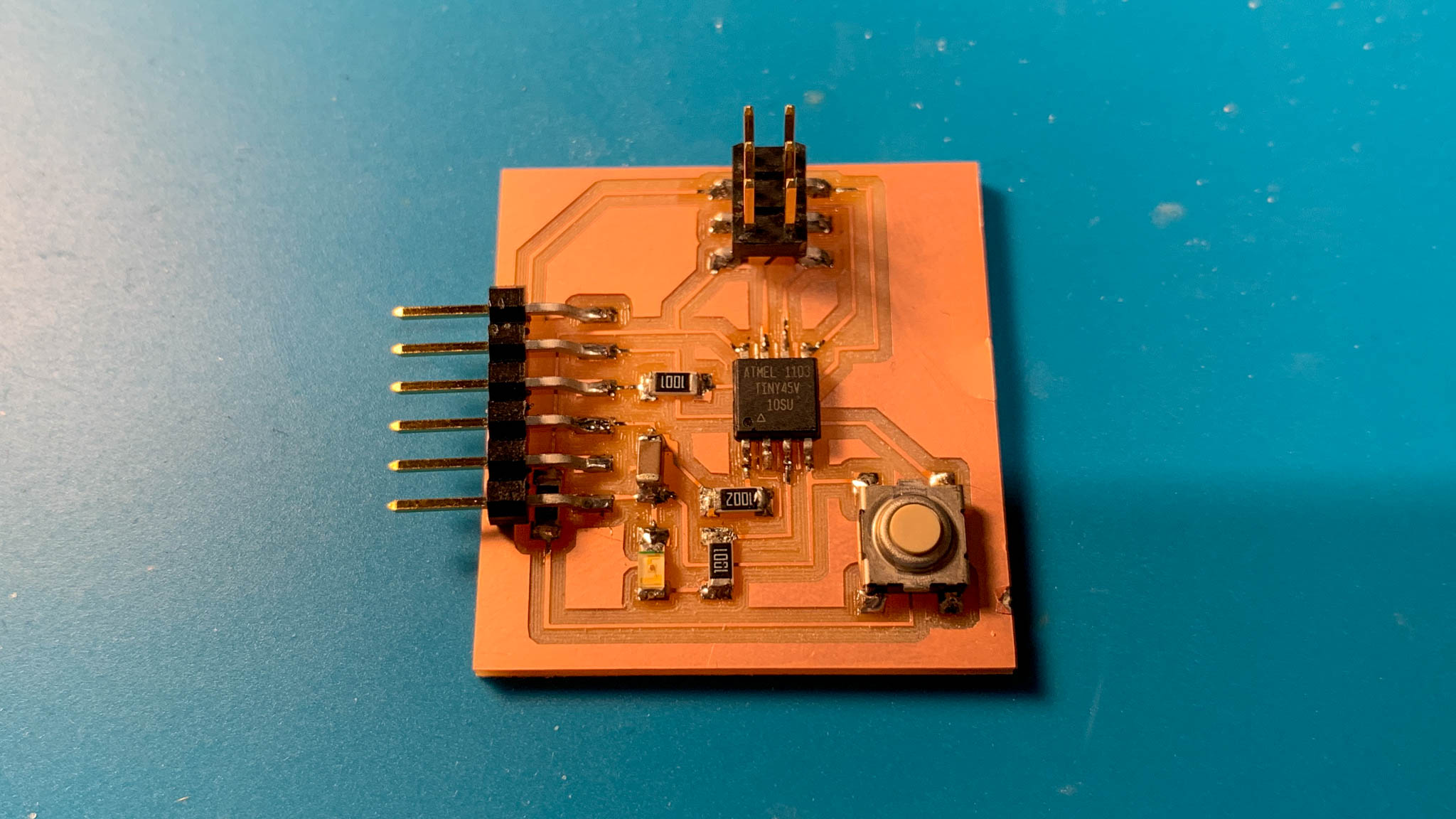
The soldering process went smoothly. I found it really difficult to tell which side the LED was supposed to be placed. Maybe somebody has a good trick out there but I had to use a magnifying glass and a bright light to notice the subtle line. I also reaized I put a resistor in front of the FTDI connector and was worried this was going to mess things up. I think however I was able to solder the jumper over the resistor and it should work out just fine.
Flashing and Testing
The flashing and testing of this board occured several weeks later during the Embedded Programming module. My documentation for flashing and testing this board can be found there. For the sake of efficency, I am not going to repeat the documentation here.
Resources
For learning Eagle, this tutorial proved to be helpful, especially around the board layout and export.
For flashing ATtiny, this tutorial was helpful.