Input devices :-
This week i had to work on senors as the input devices.In my lab there are many sensors which i can work upon.
A device that gives an output by detecting the changes in quantities or events can be defined as a sensor. In general, sensors are termed as the devices that generate an electrical signal or optical output signal corresponding to the variations in the level of inputs. There are different types of sensors, for example, consider a thermocouple which can be considered as a temperature sensor that produces an output voltage based on the input temperature changes.
All types of sensors can be basically classified into analog sensors and digital sensors. But, there are a few types of sensors such as temperature sensors, IR sensors, ultrasonic sensors, pressure sensors, proximity sensors, and touch sensors are frequently used in most electronics applications (Source: www.elprocus.com).
- Temperature Sensor
- IR Sensor
- Ultrasonic Sensor
- Touch Sensor
- Proximity Sensors
- Pressure Sensor
- Level Sensors
- Smoke and Gas Sensors
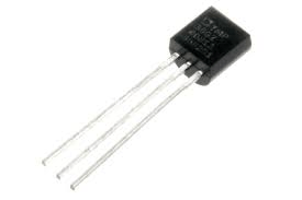
Temperature SensorTemperature is one of the most commonly measured environmental quantities for different reasons. There are different types of temperature sensors that can measure temperature, such as a thermocouple, thermistors, semiconductor temperature sensors, resistance temperature detectors (RTDs), and so on. Based on the requirement, different types of sensors are used for measuring temperature in different applications. |
 |
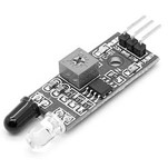
IR SensorThe small photo chips having a photocell which are used to emit and detect the infrared light are called as IR sensors. IR sensors are generally used for designing remote control technology. IR sensors can be used for detecting obstacles of the robotic vehicle and thus control the direction of the robotic vehicle. There are different types of sensors that can be used for detecting infrared lights. |
 |
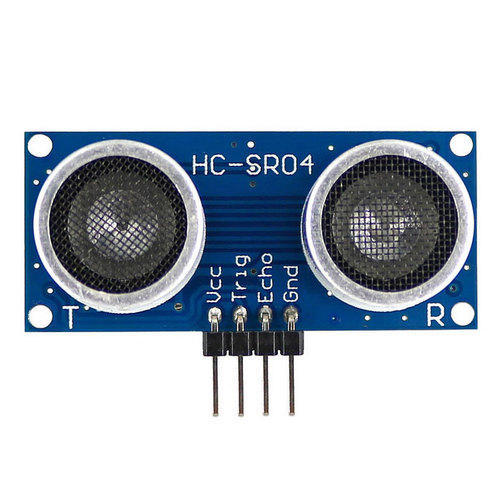
Ultrasonic SensorA transducer that works on the principle similar to the sonar or radar and estimate attributes of the target by interpreting is called an ultrasonic sensors or transceivers. There are different types of sensors that are classified as active and passive ultrasonic sensors that can be differentiated based on the working of sensors. The high-frequency sound waves generated by active ultrasonic sensors are received back by the ultrasonic sensor for evaluating the echo. Thus, the time interval taken for transmitting and receiving the echo is used for determining the distance to an object. But, passive ultrasonic sensors are just used for detecting ultrasonic noise which is present under specific conditions. |
 |
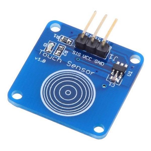
Touch SensorTouch sensors can be defined as switches that are activated by the touch. There are different types of touch sensors that are classified based on the type of touches such as capacitance touch switch, resistance touch switch, and piezo touch switch. |
 |
Like this there are so many sensors.I decided to test the Hall effect sensor and and read its output.First I tried the Hall effect sensor with the arduino board.
Hall Effect Sensor:-
This module is used to detect the presence of magnetic. Whenever, it will be placed in the region of magnetic field then it will detect it and will give us the output. The module consists of a hall sensor which detects the presence of magnetic field.This module can be used in many projects like making a door alarm in which whenever the door will close, the magnetic will come near to the module, so it will detect the magnet.It can also be used in making speedometer for car or a bike. If a magnet is attached to the wheel and we have place this module in the body, then we can know the time taken to complete a cycle and by doing further calculation, we can calculate the speed.
How hall effect sensor works?
The analog hall sensor module contains a hall sensor. The hall sensor works on the principle of Hall Effect, which states the whenever a magnetic field is applied in perpendicular direction to the flow of the current, then a potential difference is induced. We can use this voltage to detect that whether the magnetic is placed near the sensor or not.
So the Hall-Effect is the production of a voltage difference (the Hall voltage) across an electrical conductor, transverse to an electric current in the conductor and to an applied magnetic field perpendicular to the current.Here in the media below you can see a simple visualisation of the effect (Source: Wikipedia):
For this i am using KY-024 module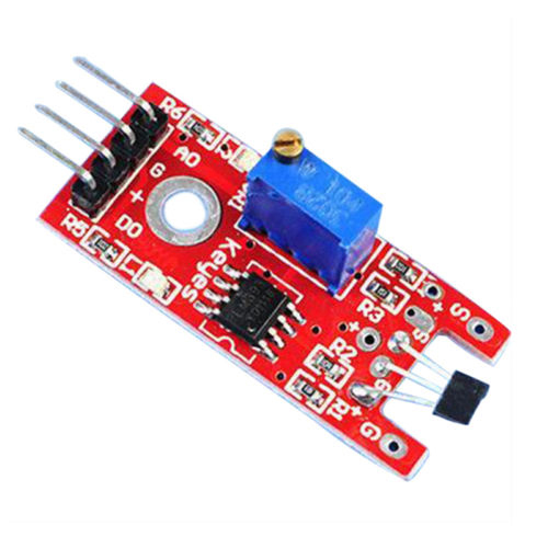
Following is the Pin Configuration of the Hall Effect Sensor KY-024 Module 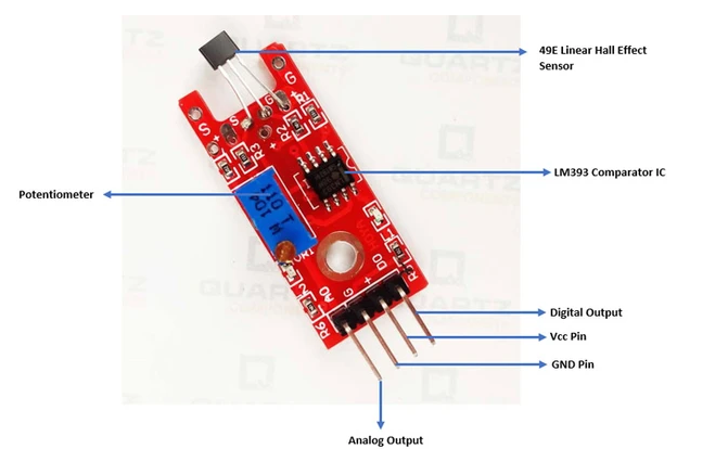
I Connected the Hall Effect sensor as per the following circuit connections 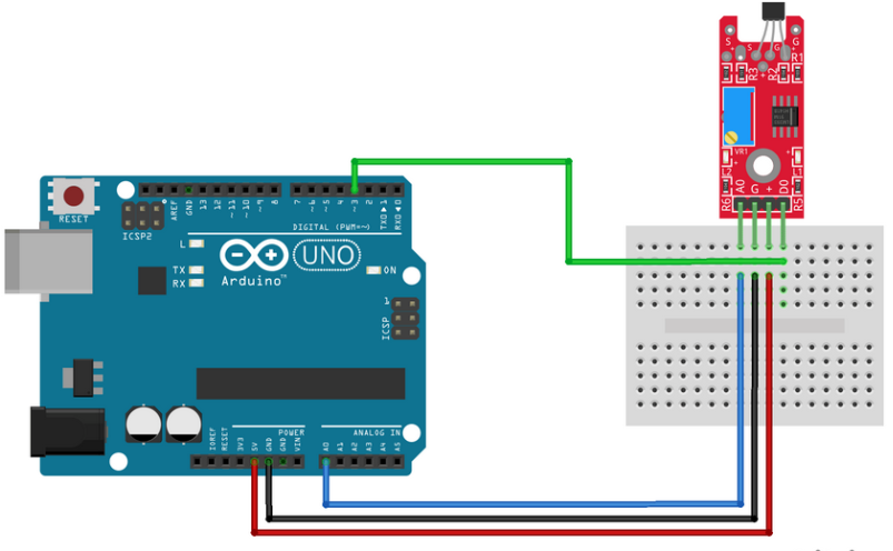
I connected the senosor as shown in the pic.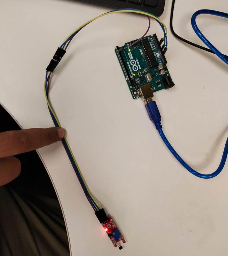
Connect board's power line (+) and ground (G) to 5V and GND respectively. Connect the digital signal (D0) to pin 3 on the Arduino and the board's analog signal (A0) to pin A0 on the Arduino.
| KY-024 | Arduino |
| A0 | A0 |
| G | GND |
| + | 5V |
| D0 | 3 |
I Wrote the following program for the sensing of Haleffect sensor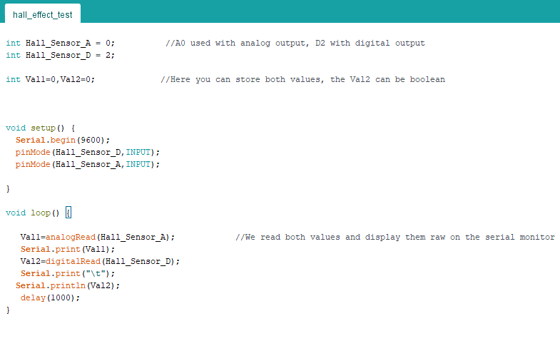
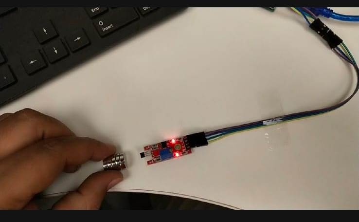
When i movw the magnet far the sensor as shown in the pic the led dows not glow in the sensor module and when near led glows 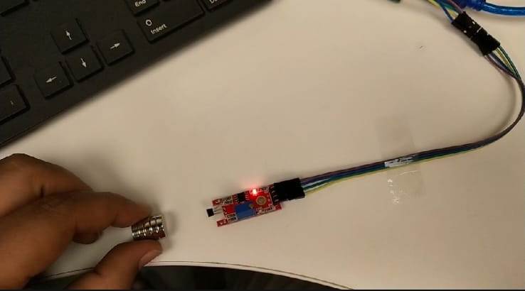
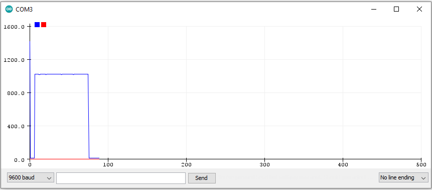
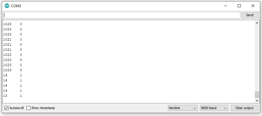
Here are the plotter graphs when the magnetic field is not detected and when detected.
| Magnetic Field | Not detected | Detected |
| Serial Plotter | 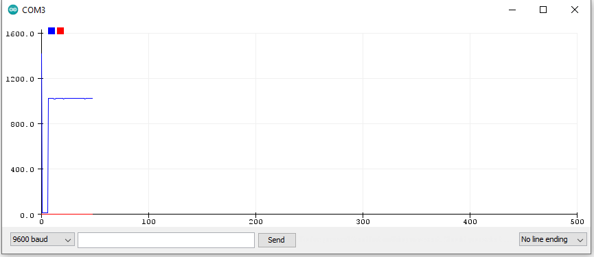 |
 |
| Serial Monitor | 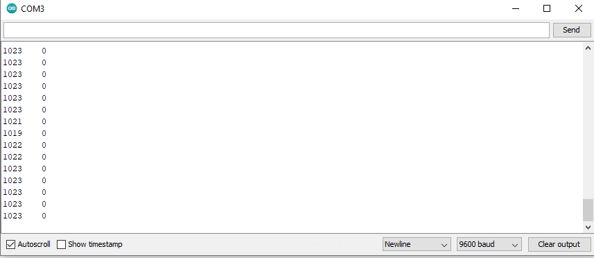 |
 |
Here is the video of my excercise
After Joining the fablab after COVID i made the PCB using the Ultrasonic sensor HC-SR04.
An ultrasonic sensor is an instrument that measures the distance to an object using ultrasonic sound waves.An ultrasonic sensor uses a transducer to send and receive ultrasonic pulses that relay back information about an object’s proximity. High-frequency sound waves reflect from boundaries to produce distinct echo patterns.
How It works.
Ultrasonic sensors work by sending out a sound wave at a frequency above the range of human hearing. The transducer of the sensor acts as a microphone to receive and send the ultrasonic sound. Our ultrasonic sensors, like many others, use a single transducer to send a pulse and to receive the echo. The sensor determines the distance to a target by measuring time lapses between the sending and receiving of the ultrasonic pulse.
The working principle of this module is simple. It sends an ultrasonic pulse out at 40kHz which travels through the air and if there is an obstacle or object, it will bounce back to the sensor. By calculating the travel time and the speed of sound, the distance can be calculated.
Ultrasonic sensors are a great solution for the detection of clear objects. For liquid level measurement, applications that use infrared sensors, for instance, struggle with this particular use case because of target translucence.
For presence detection, ultrasonic sensors detect objects regardless of the color, surface, or material (unless the material is very soft like wool, as it would absorb sound.)
To detect transparent and other items where optical technologies may fail, ultrasonic sensors are a reliable choice.
This can measure a distance of range from 2 cm to 400 cm with an accuracy of 3mm. The HC- SR04 modules consist of a transmitter, receiver and control circuit.
An optical sensor has a transmitter and receiver, whereas an ultrasonic / level sensor uses a single ultrasonic element for both emission and reception. In a reflective model ultrasonic / level sensor, a single oscillator emits and receives ultrasonic waves alternately. This enables miniaturisation of the sensor head.
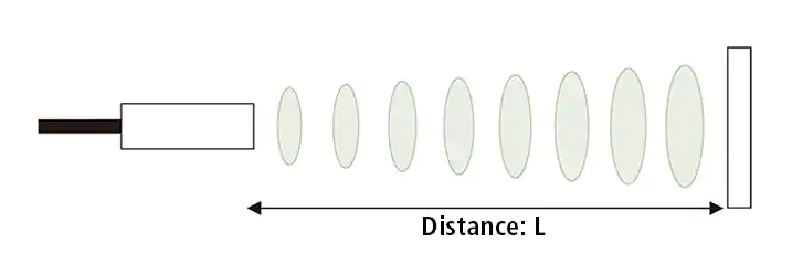
Distance calculation
The distance can be calculated with the following formula:
Distance L = 1/2 × T × C
where L is the distance, T is the time between the emission and reception, and C is the sonic speed. (The value is multiplied by 1/2 because T is the time for go-and-return distance.)
Pin Out For the Ultrasonic Sensor
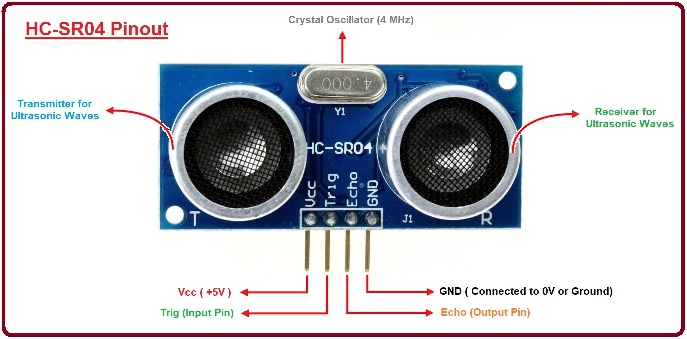
| No. | Pin Name | Pin Description |
| 1 | VCC | The power supply pin of the sensor that mainly operates at 5V DC. |
| 2 | Trig Pin | It plays a vital role to initialize measurement for sending ultrasonic waves. It should be kept high for 10us for triggering the measurement. |
| 3 | Echo Pin |
This pin remains high for short period based on the time taken by the ultrasonic waves to bounce back to the receiving end. |
| 4 | Ground | This pin is connected to ground. |
| Parameter | Value |
| Main Parts | Transmitter & Receiver |
| Technology Used | Non-Contact Technology |
| Operating Voltage | 5 V |
| Operating Frequency | 4 MHz |
| Detection Range | 2cm to 400cm |
| Measuring Angle | 30º |
| Resolution | 3mm |
| Operating Current | <15mA |
| Sensor Dimensions | 45mm x 20mm x 15mm |
PCB Design
I started with PCB design using EAGLE software.
- ATtiny44 x 1
- Resistor 499ohm x 1
- Capacitor 10uf x 1
- ISP header (3x2 pin) x 1
- FTDI header (1x6 pin) x1
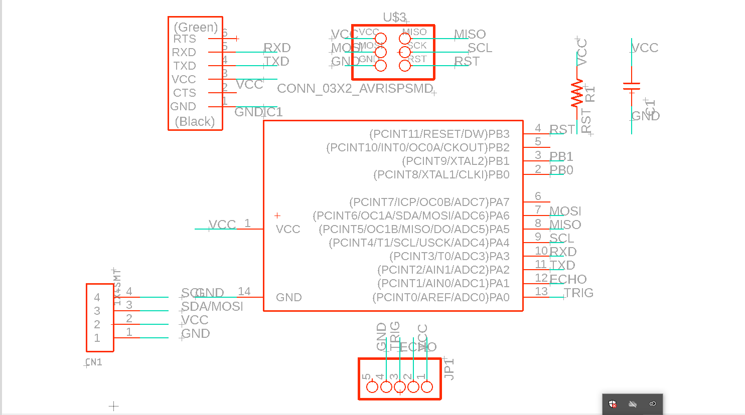
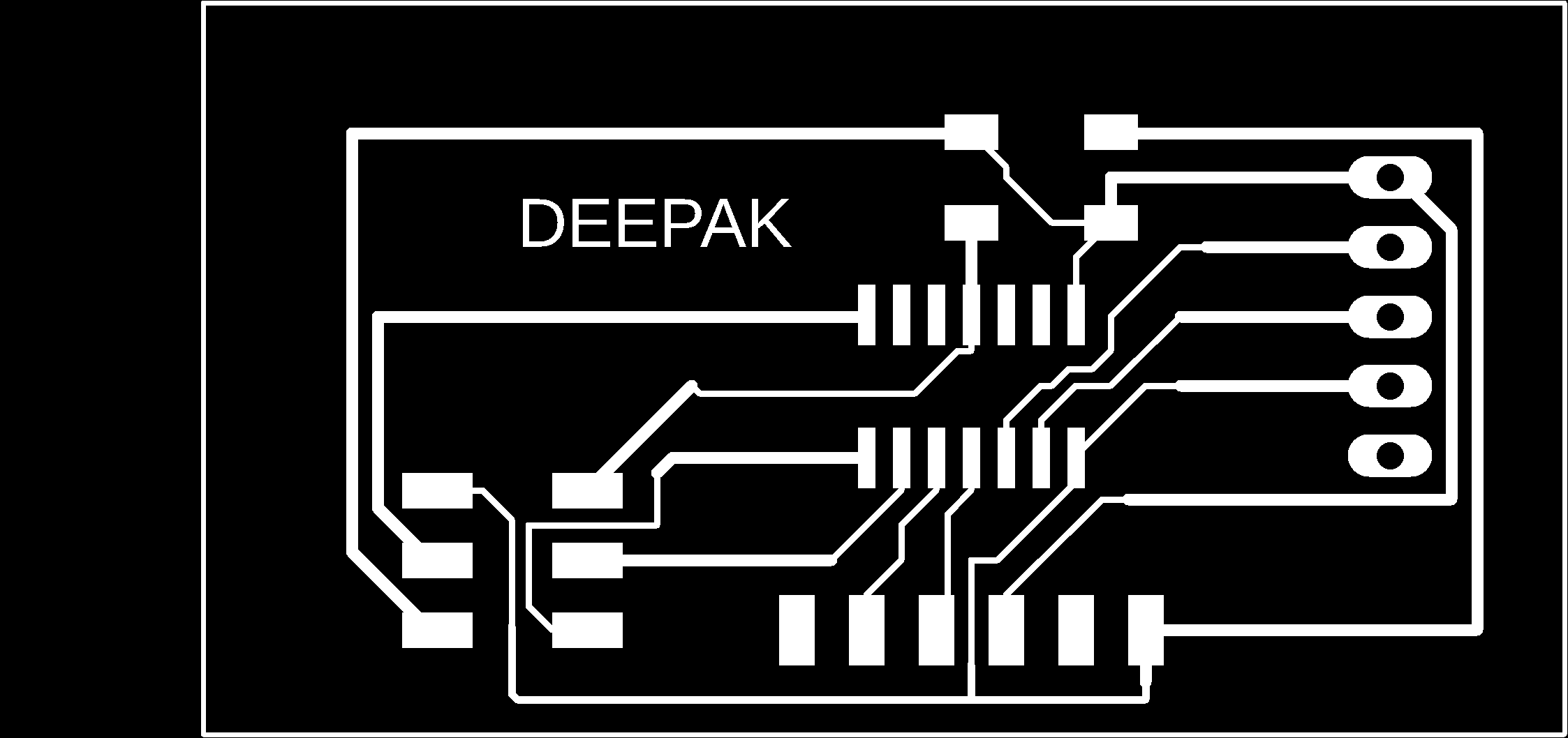
After adding the components i switched to auto route , but it was mess so i had to routed it mannually .i gave the designing rules from the Electronics Design Week .
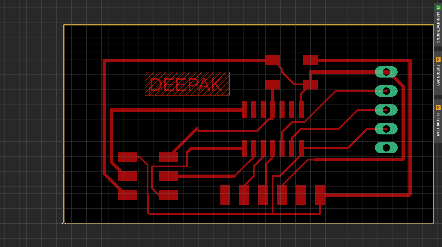
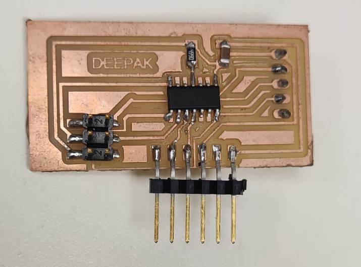
After this i milled the PCB and Soldered the components usig the SRM-20 Desktop Miller.I followed the Electronics Production Weeek assignment and soldered the components.I lost the mobile,my assignment photo graphs were in that mobile so i could not post the video the milling and soldering.
I Uploaded the following code
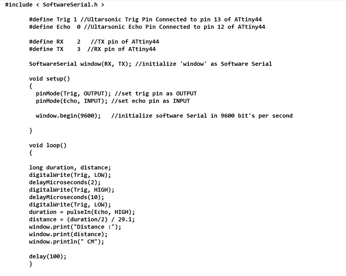
Here is the video of the excercise
The files of this week can be downloaded here