Electronics Design :-
Group Asignment
- use the test equipment in your lab to observe the operation of a microcontroller circuit board.
It would help us understand
1) The working of multimeter
2) Using Power Supply
3)Understand Test Equipment
4)Working of OScilloscope.
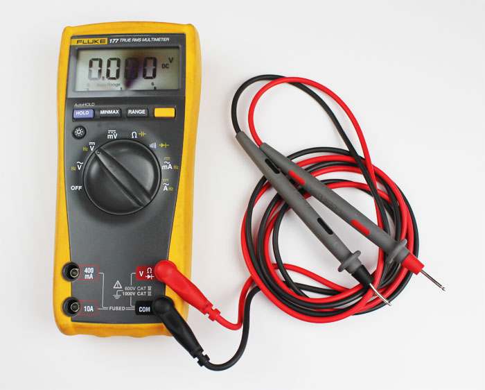
Multimeter:-
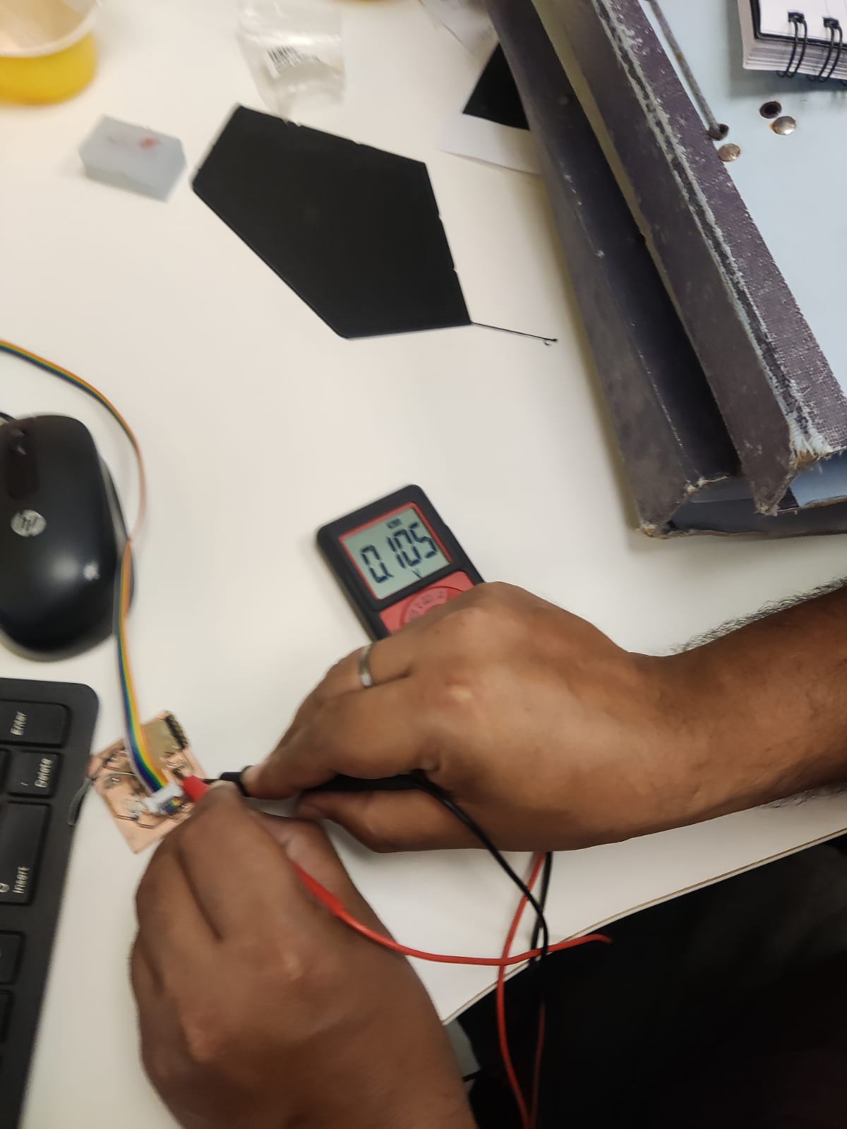
A multimeter is an electronic tool used to measure voltage, amps and resistance across circuits.By attaching two leads to different parts of an electrical system, professionals can use multimeters to detect levels of voltage and resistance, or changes in electrical currents. In the lab we used the multimeter to check the continuty in the circuit board and calculate the value of the resistence and measure the forward volatage.
In the lab used the oscillo scope.
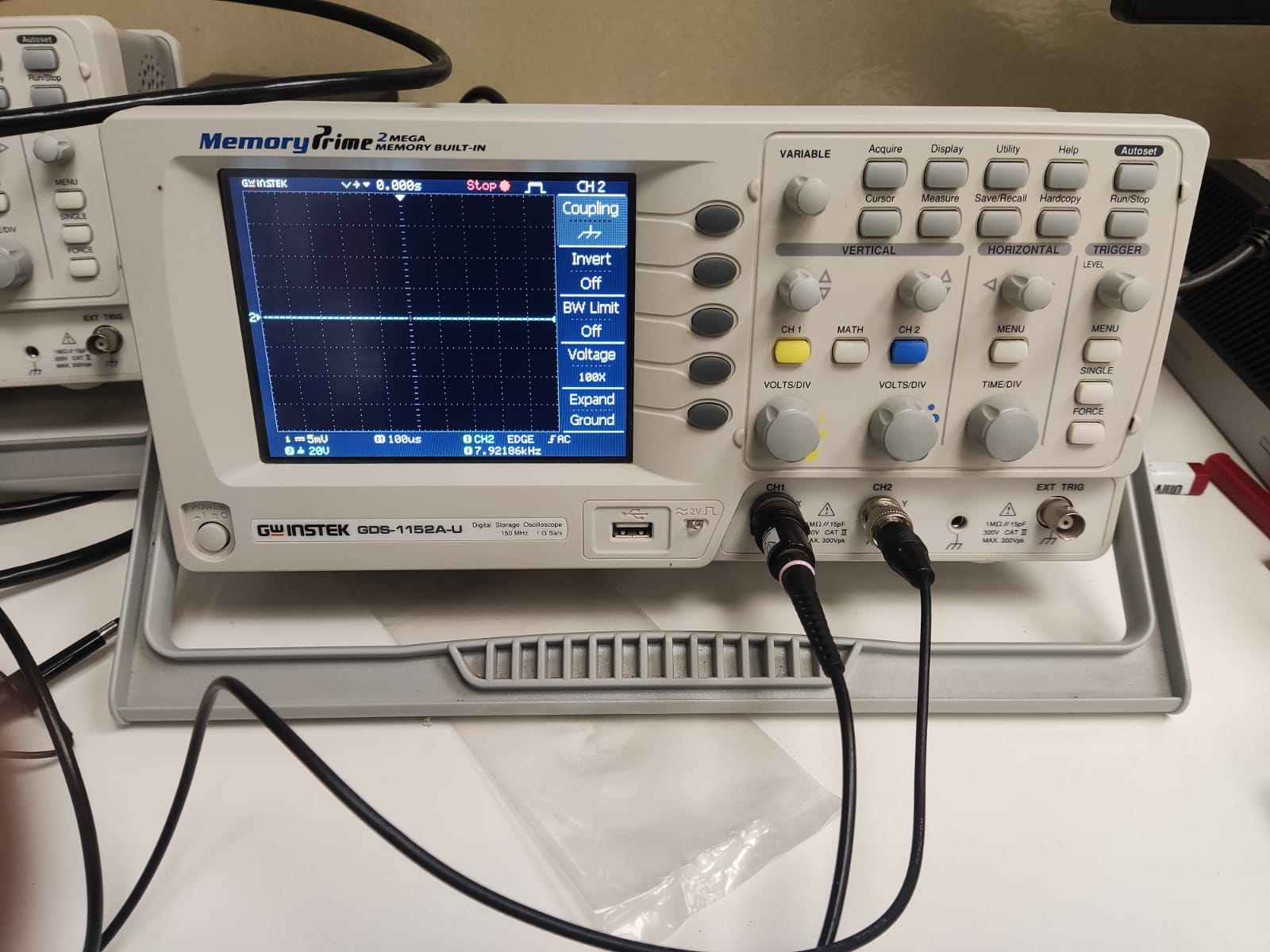
An oscilloscope is an instrument that graphically displays electrical signals and shows how those signals change over time. We can use oscilloscopes to measure electrical phenomena and quickly test, verify, and debug their circuit designs. The primary function of an oscilloscope is to measure voltage waves
Individual Assignment
This week Assignment redraw an echo hello-world board,add (at least) a button and LED (with current-limiting resistor) check the design rules, make it, and test it
extra credit: simulate its operation
Electronics Basics
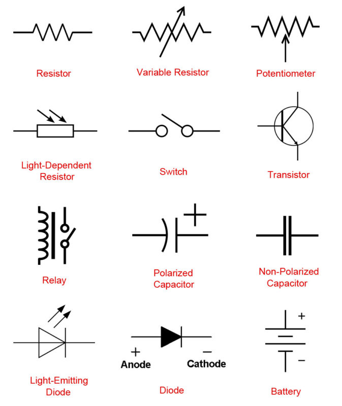
1) Components Symbol
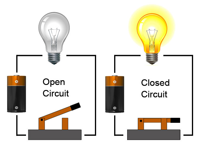
2)What Is A Circuit?
Before you design an electronic project, you need to know what a circuit is and how to create one properly.
An electronic circuit is a circular path of conductors by which electric current can flow. A closed circuit is like a circle because it starts and ends at the same point forming a complete loop. Furthermore, a closed circuit allows electricity to flow from the (+) power to the (-) ground uninterrupted.if there is any break in the flow of electricity, this is known as an open circuit. As shown below, a switch in a circuit can cause it to be open or closed depending on it’s position.
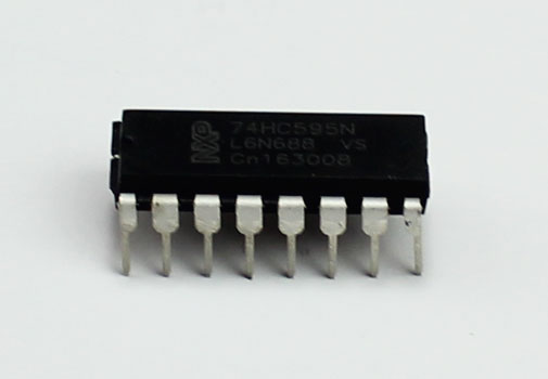
3)Integrated Circuit (IC)
An integrated circuit is a circuit that’s been reduced in size to fit inside a tiny chip. This circuit contains electronic components like resistors and capacitors but on a much smaller scale. Integrated circuits come in different variations such as 555 timers, voltage regulators, microcontrollers and many more. Each pin on an IC is unique in terms of it’s function.
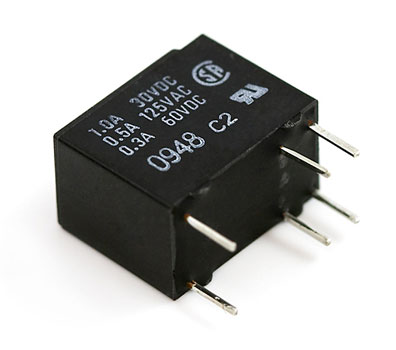
4)Relay
A relay is an electrically operated switch that opens or closes when power is applied. Inside a relay is an electromagnet which controls a mechanical switch.
![]()
5)Transistor
Transistor are tiny switches that turn a current on or off when triggered by an electric signal. In addition to being a switch, it can also be used to amplify electronic signals. A transistor is similar to a relay except with no moving parts.
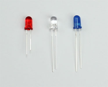
6)Light-Emitting Diode (LED)
A light-emitting diode is like a standard diode in the fact that electrical current only flows in one direction. The main difference is an LED will emit light when electricity flows through it. Inside an LED there is an anode and cathode. Current always flows from the anode (+) to the cathode (-) and never in the opposite direction. The longer leg of the LED is the positive (anode) side.
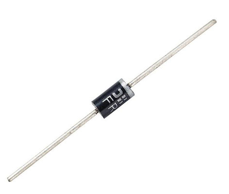
7)Diode
A diode allows electricity to flow in one direction and blocks it from flowing the opposite way. The diode’s primary role is to route electricity from taking an unwanted path within the circuit.
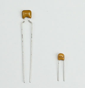
8)Capacitor
Capacitors store electricity and then discharges it back into the circuit when there is a drop in voltage. A capacitor is like a rechargeable battery and can be charged and then discharged. The value is measured in F (Farad), nano Farad (nF) or pico Farad (pF) range.
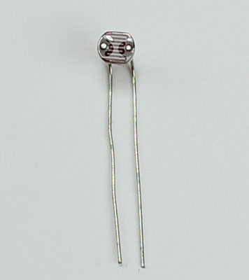
9)Light-Dependent Resistor (LDR)
A light-dependent resistor is also a variable resistor but is controlled by the light versus turning a knob. The resistance in the circuit changes with the intensity of the light. These are often found in exterior lights that automatically turn on at dusk and off at dawn.
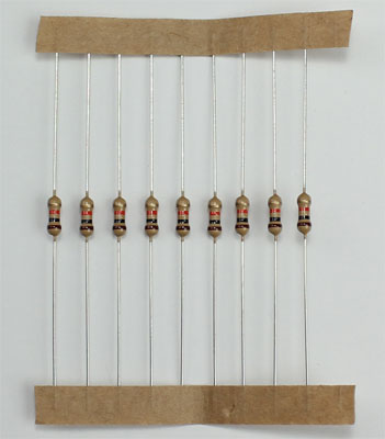
10)Resistor
Resistors are used to resist the flow of current or to control the voltage in a circuit. The amount of resistance that a resistor offers is measured in Ohms. Most resistors have colored stripes on the outside and this code will tell you it’s value of resistance. You can use a multimeter to determine the value of a resistor.
11)Digital Multimeter
A multimeter is a device that’s used to measure electric current (amps), voltage (volts) and resistance (ohms). It’s a great for troubleshooting circuits and is capable of measuring both AC and DC voltage.
12)Kirchhoffs First Law – The Current Law, (KCL)
Kirchhoffs Current Law or KCL, states that the “total current or charge entering a junction or node is exactly equal to the charge leaving the node as it has no other place to go except to leave, as no charge is lost within the node“. In other words the algebraic sum of ALL the currents entering and leaving a node must be equal to zero, I(exiting) + I(entering) = 0. This idea by Kirchhoff is commonly known as the Conservation of Charge.
13)Microprocessor
Microprocessor Unit do not have memory . They use external memory to provide program and data storage. The program is typically stored in non-volatile memory, such as NAND or serial Flash. At start-up, this is loaded into an external DRAM and execution commences. This means the MPU will not be up and running as quickly as an MCU but the amount of DRAM and NVM you can connect to the processor is in the range of hundreds of Mbytes and even Gbytes for NAND.
14)Microcontroller
Micro Controller Unit uses on-chip embedded Flash memory in which to store and execute its program. Storing the program this way means the MCU having a shorter start-up period and executing code quickly. The only practical limitation to using embedded memory is that the total available memory space is finite. Most Flash MCU devices available on the market have a maximum of 2 Mbytes of Program memory. This may prove to be a limiting factor, depending on the application.
ATTiny 44,45 have 4 KB of Memory and ATTiny 85 have 8KB of memory
Schematic designing the Hello Echo World Board
For this I used the Eagle Software.
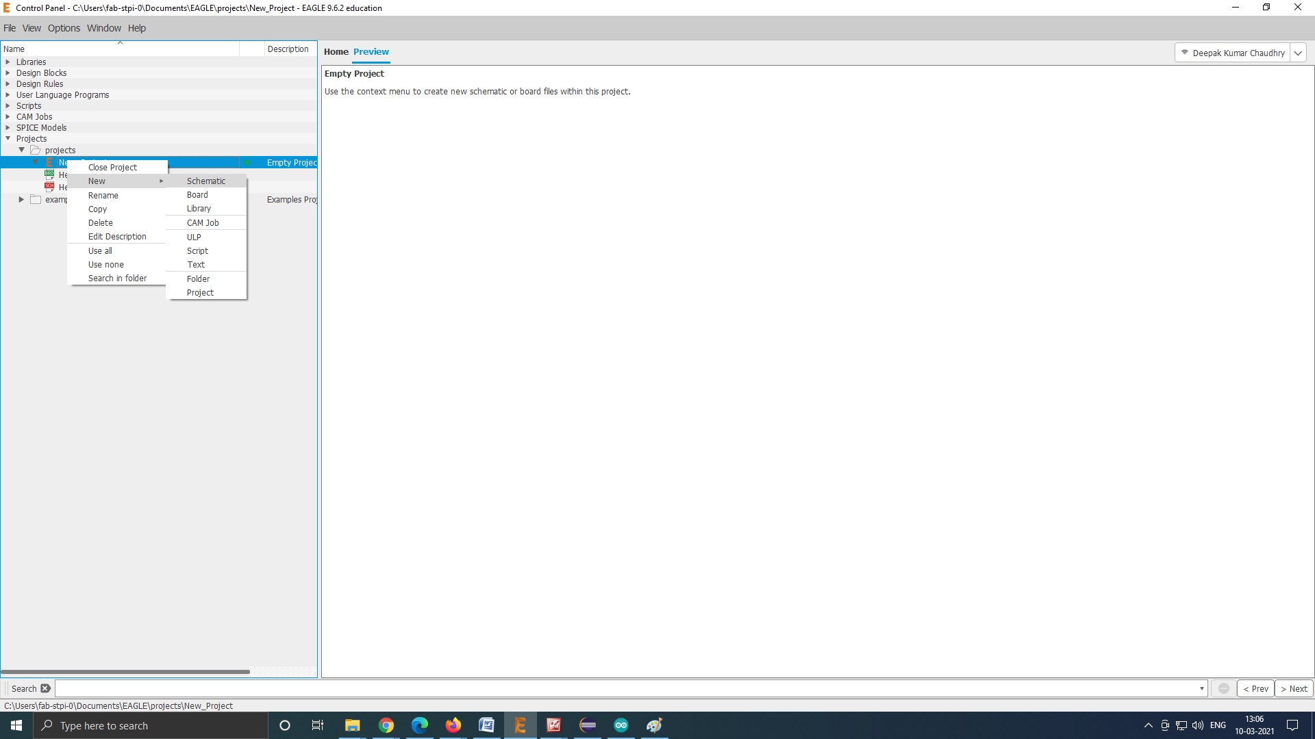
Create a new project
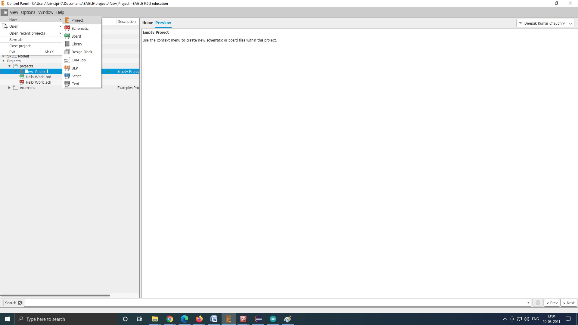
create a new schematic
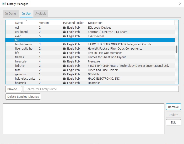
Now Download the eagle fab library from here.Then i added the eagle fab library to the eagle/library directory and confirmed whetehr it is in use.
Then I added the components
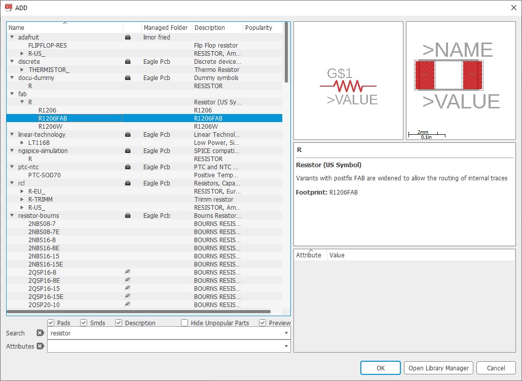
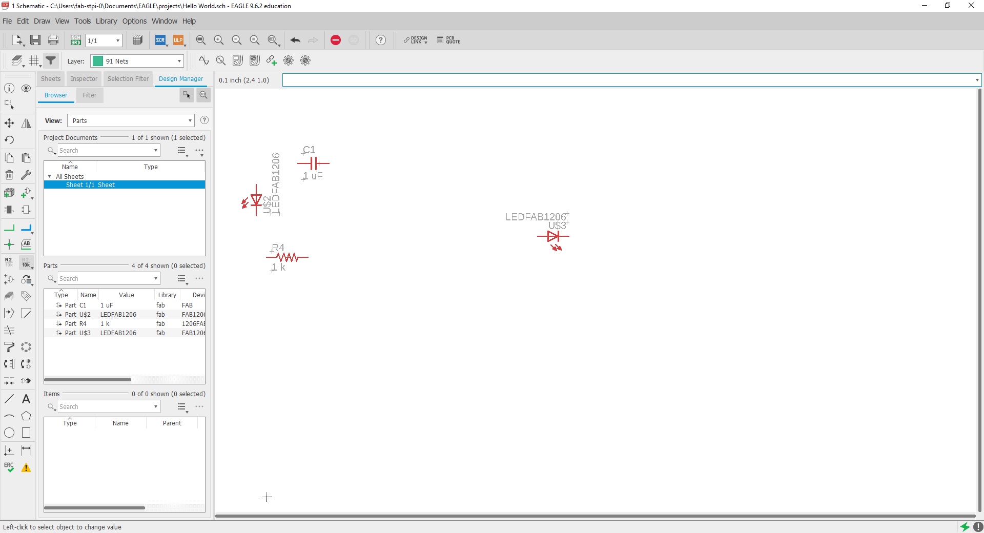
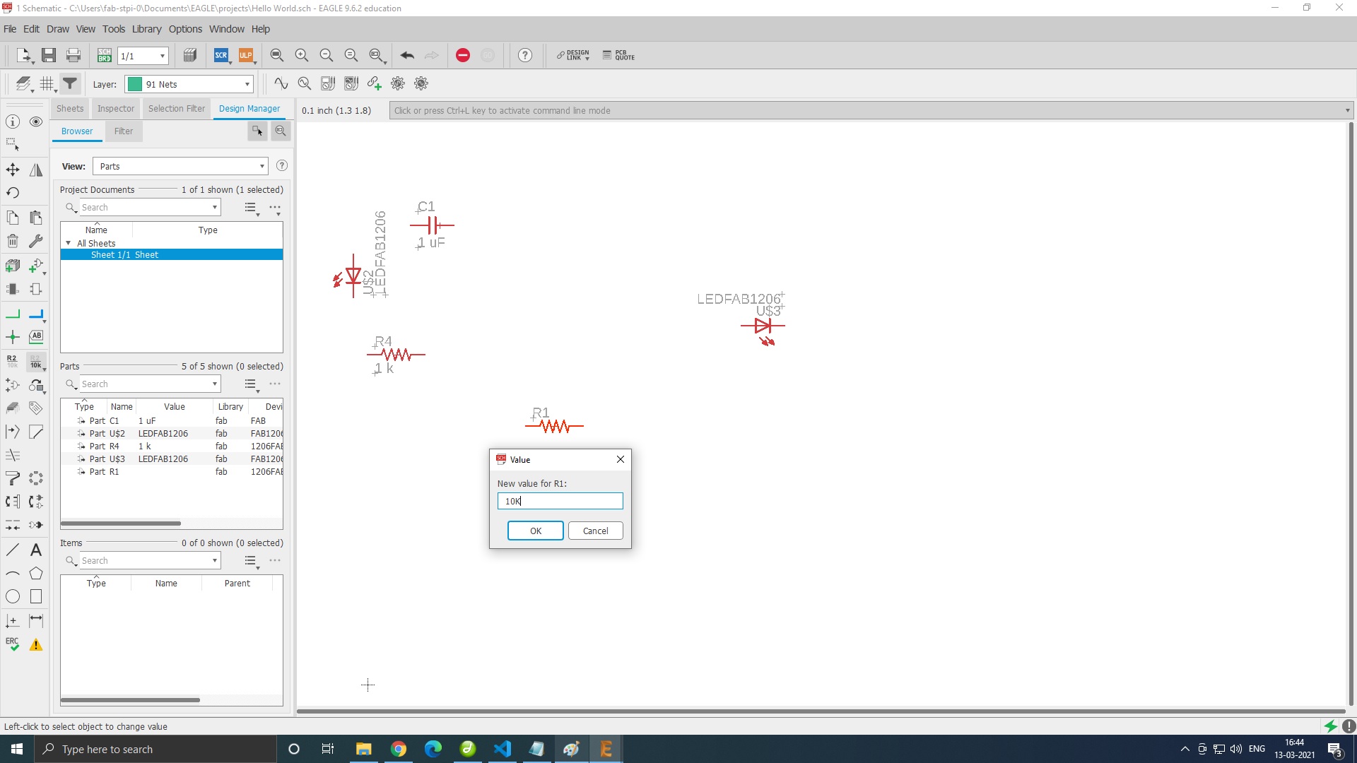
Then i gave the value of the components
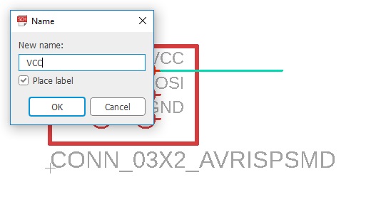
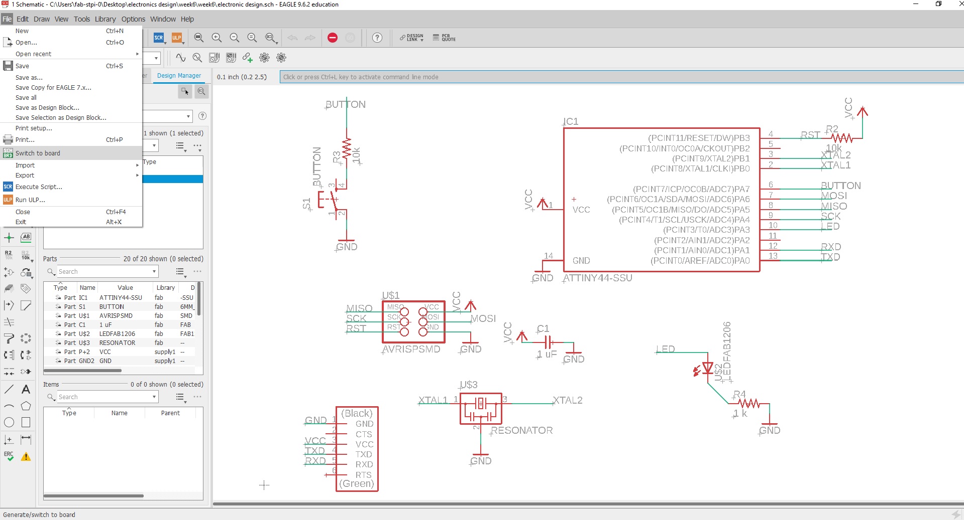
I made the connection using the 'Line' tool and 'Name' tool.
But in the assignment requires me to connect an LED and a push button, I updated the schematic diagram accommodating both.
The component can be moved, rotated and mirrored by clicking on the following icons from the tool bar, then click on the component itself.
Name the pins by typing name in the command line. Change the name to the desired(here VCC) in the popup.
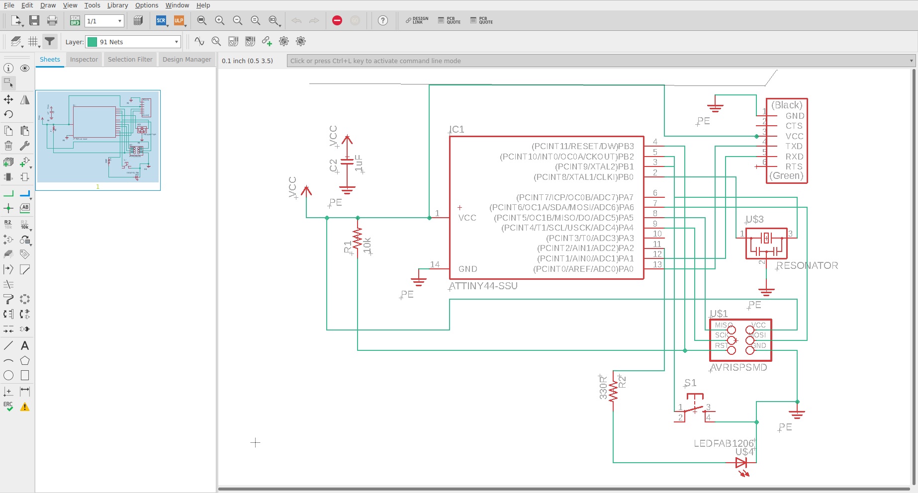
My Final circuit was as following.
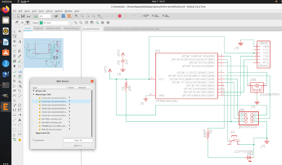
Check for errors using ERC button in the tool bar.
The output of my ERC check:
The value of the current limiting resistor was calculated using V=IR
V-Forward voltage of LED (1.8 V)
I-Forward curent (20mA)
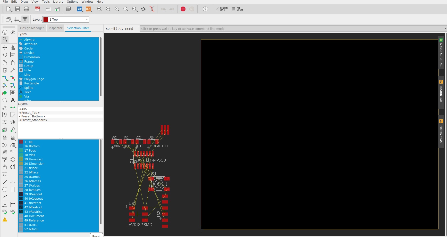
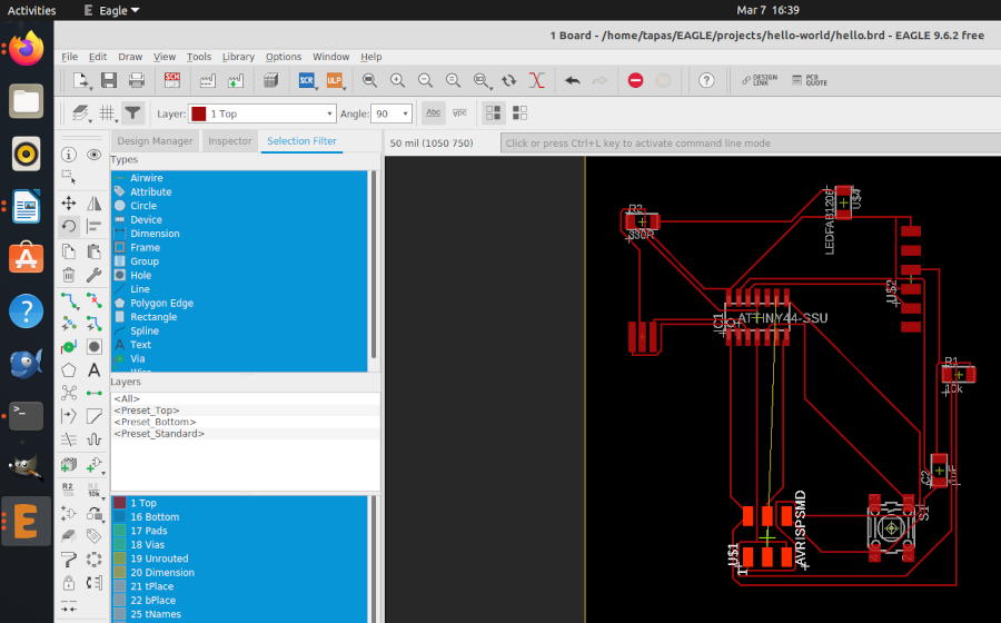
After i switched to Board Design

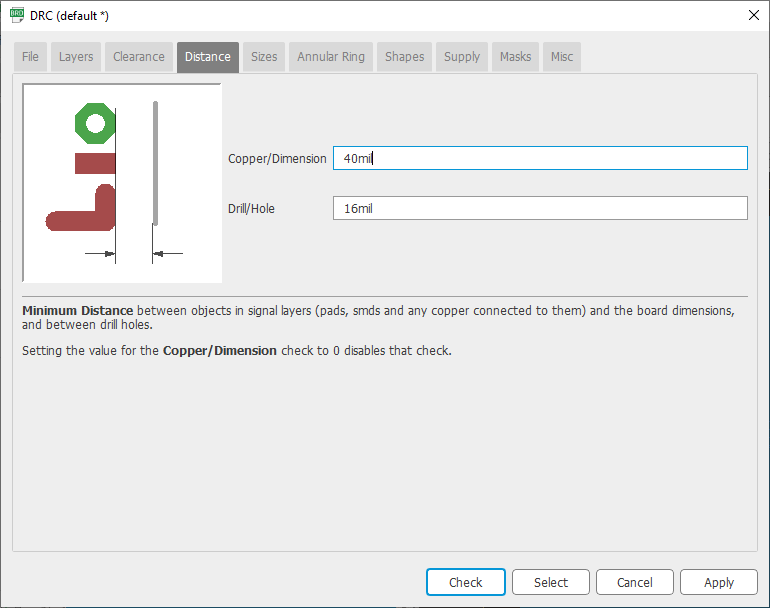
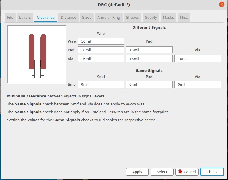
After this I checked the design rules.Initially the width under the clearnce tab was 6 mil but we changed it to 16 mil.
Note 1 Inch = 1000 Mils.For trace cut we use 1/64 Bit.so we calculated it to 15.625 mil and gave the width as 16 mils.
But on searching the fabacademy profiles of one of the student (Not remembering the name will update it later ) found the set of good designing rules.
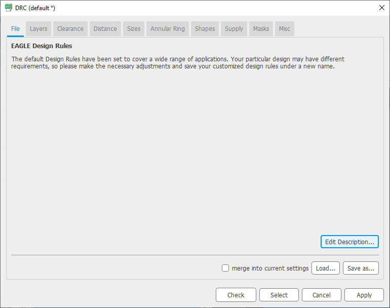
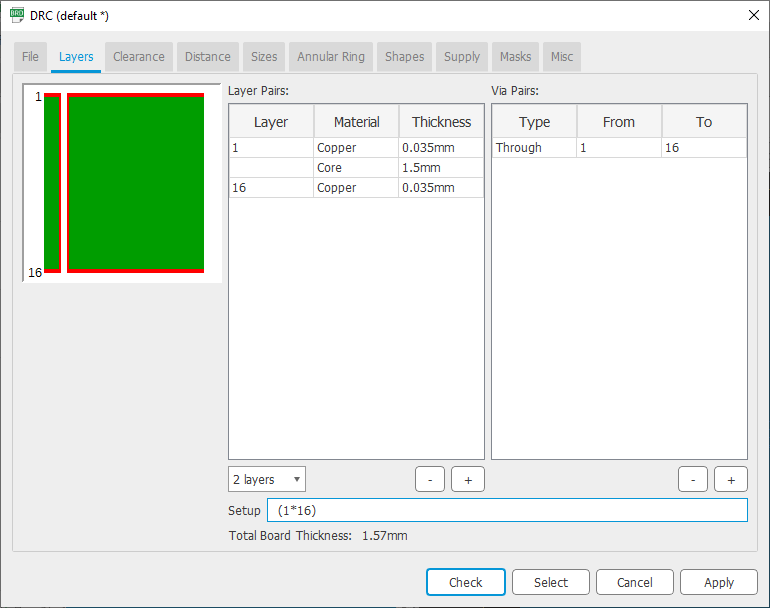
![]()
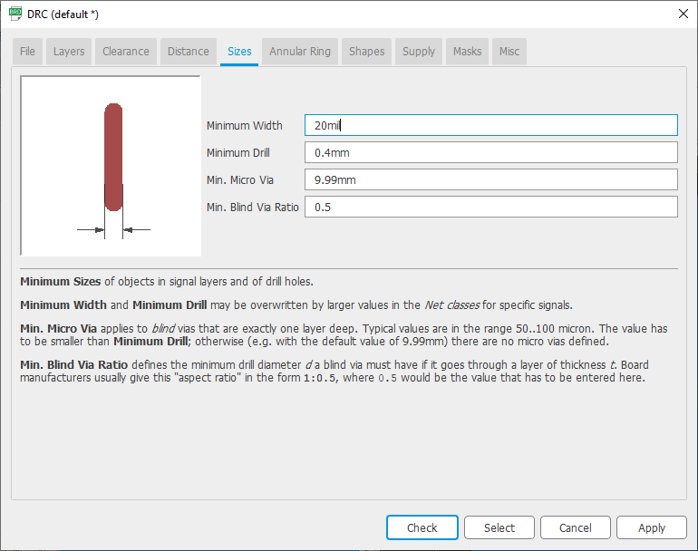
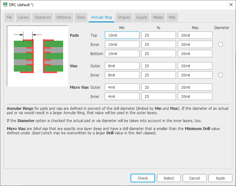
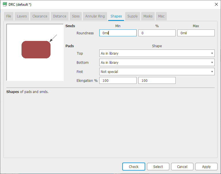
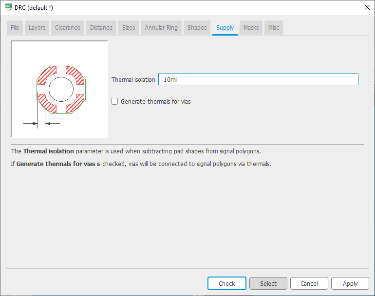
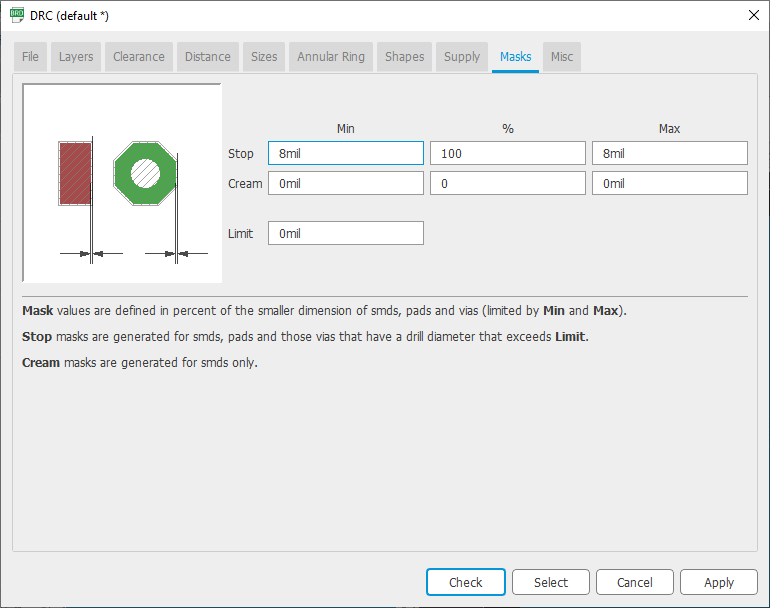
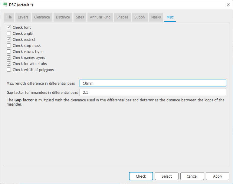
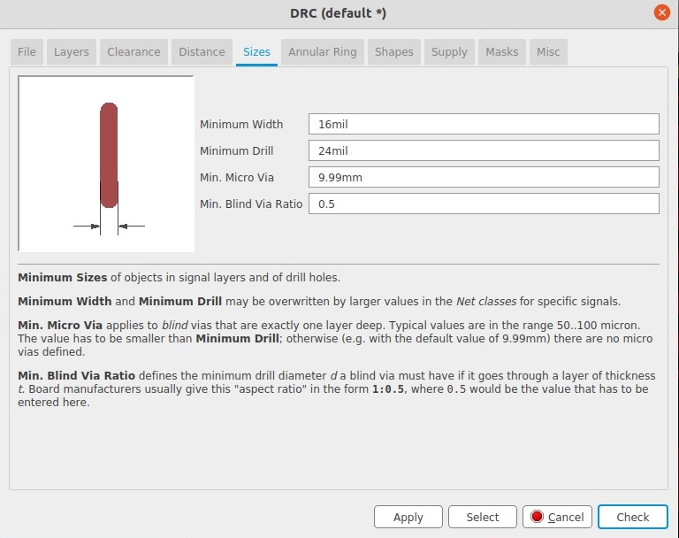
similarly under sizes tab we gave 16 mils..
Then after this we used the auto rout features under the tools tab with high efforts 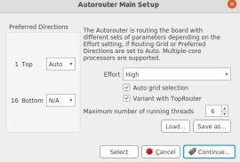
But I got errors the routs were intersecting and sometime it gives the routing for double sided PCB.I tried this with low efforts but same problem persisted
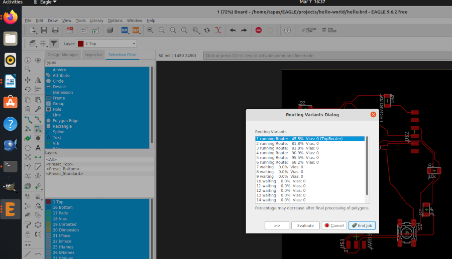
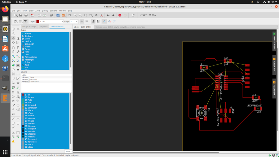
i asked my instructor regarding this problem Mr.Sheebu.He advised to do routing of the small circuit mannually.So finally i decided to redraw it again mannually. And suceeded.
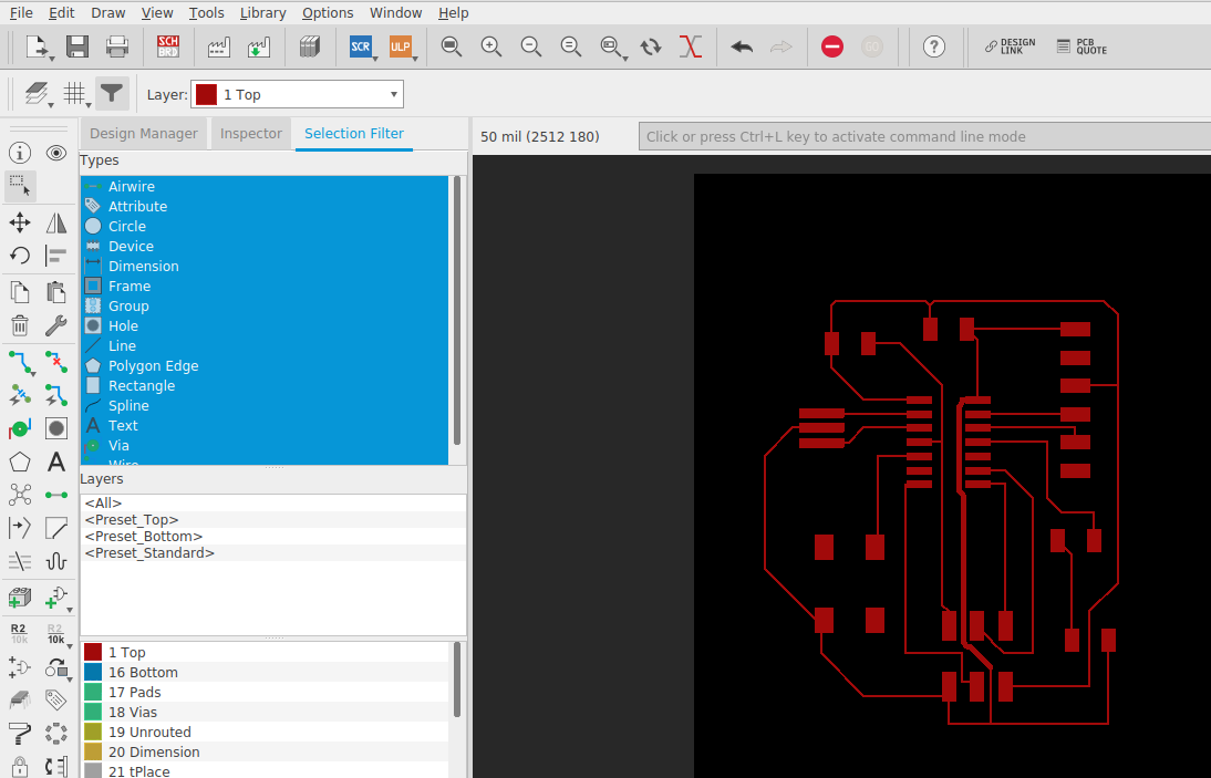
Once you are done with your board layout. You can do the following commands:
- “ratsnest”, to compile the design.
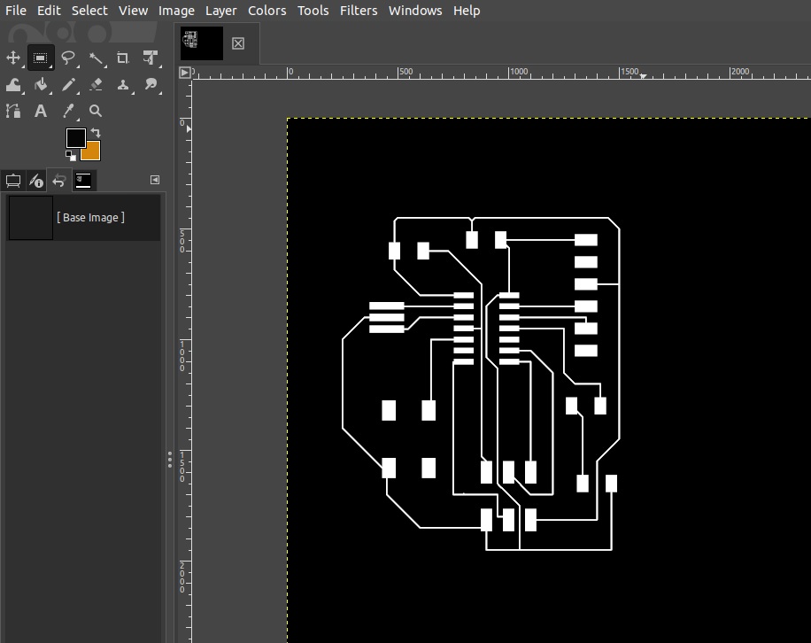
- “display none top”, this will display just the top layer (copper and traces layer).
- “export image”, this will enable you to export as .png. Select Monochrome and 1000 dpi.
- “display none dim”. this will display just the dimension layer which is the outline.
- “export image”, same setting but different name (eg. outline.png
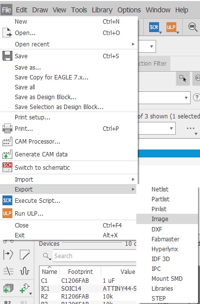
Now export the file 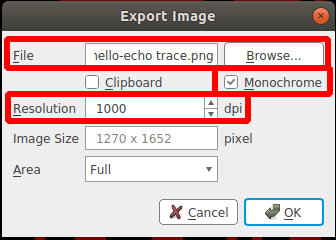
Go to 'FILE' on the taskbar and click 'EXPORT' and select 'IMAGE'. Then a window opens and browse
the destination, make it monochrome and change the resolution to 1000dpi.
export the file as png as the same way we exported the the traces. After this created the cut file in the GIMP software after opening this image in GIMP.
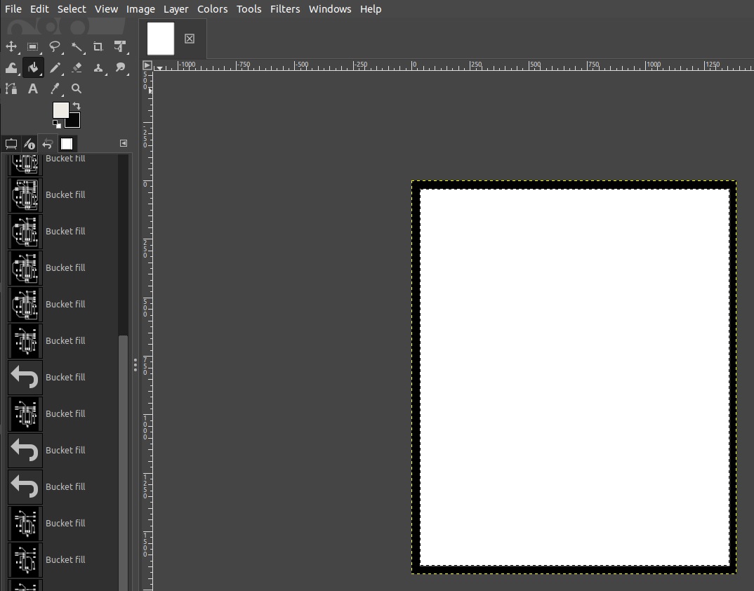
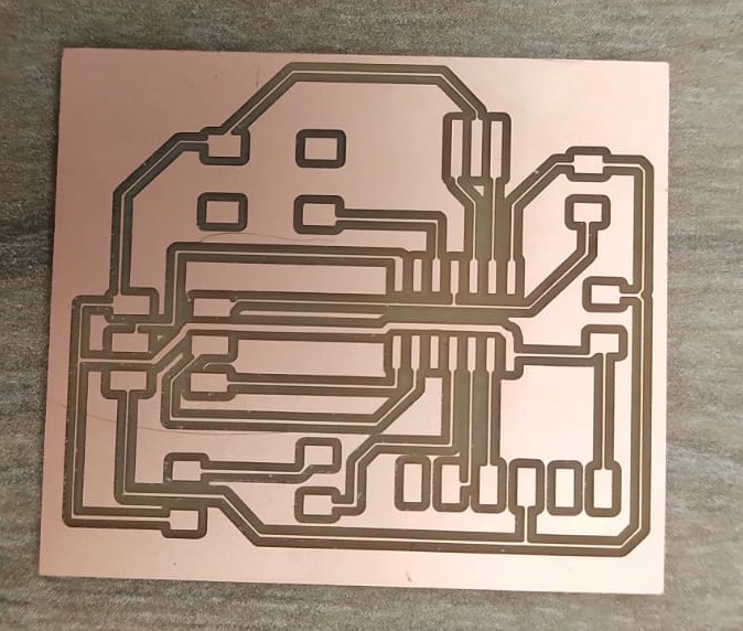
I Got The Traces and the Cut File.I milled tha circuit.I milled the circuit using the 16 mil.But in future i will use the designng rules which i had discussed above.
For the milling procedure please visit here which i learnt in the fabzero training.
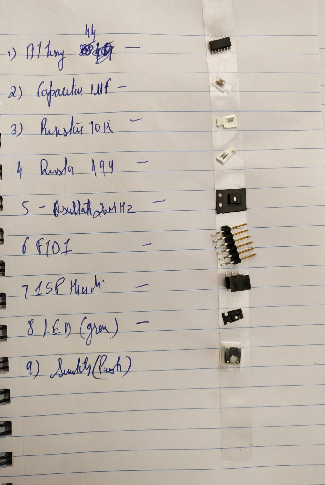
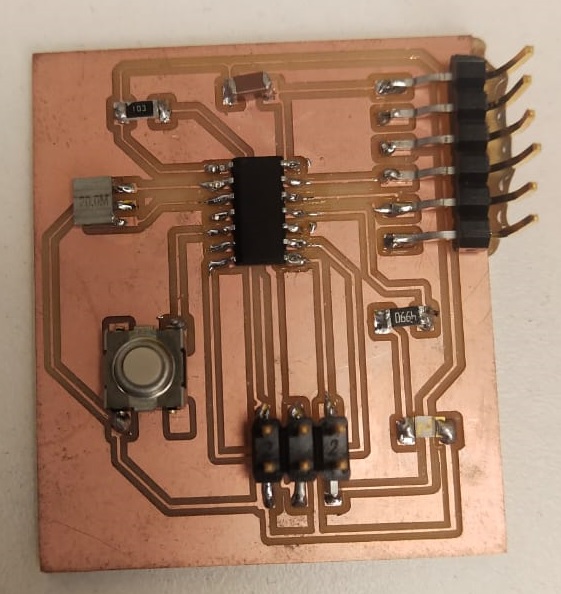
Then I git add soldered all the components
Here I Git My PCB
Before Programming I had to flash Bootloader in the attiy 44.
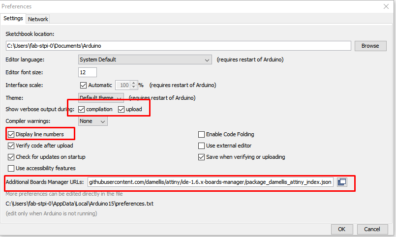
For this open the ardiuno IDE and open the prefrences
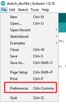
In the settings window I check the options for verbose output and Display line numbers
In the field for the additional Boards Manager URL we add:
https://raw.githubusercontent.com/damellis/attiny/ide-1.6.x-boards-manager/package_damellis_attiny_index.json
Then we open up the Boards Manager
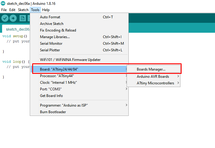
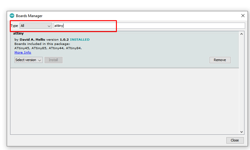
There we search for attiny and install the latest version
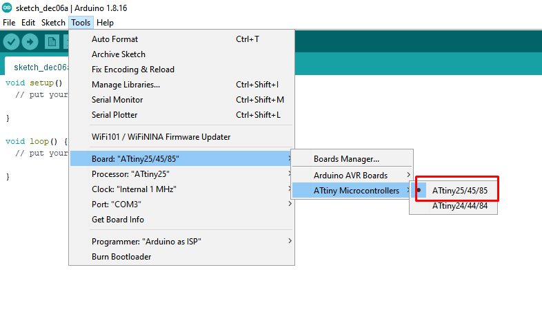
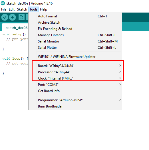
Now we are able to work with the ATTiny. For my hello-world board I used the ATTiny45, so I choose ATtiny25/45/85 in the boards list.
\
If we open the Tools Menu again, then there are more options now, for the ATTinys.
There I activated the ATtiny45 as the processor, with the Internal 8 Mhz Clock.
\
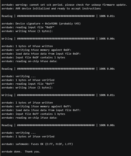
Flashing the bootloader
The ATTiny needs a Bootloader first, which defines the clock speed.
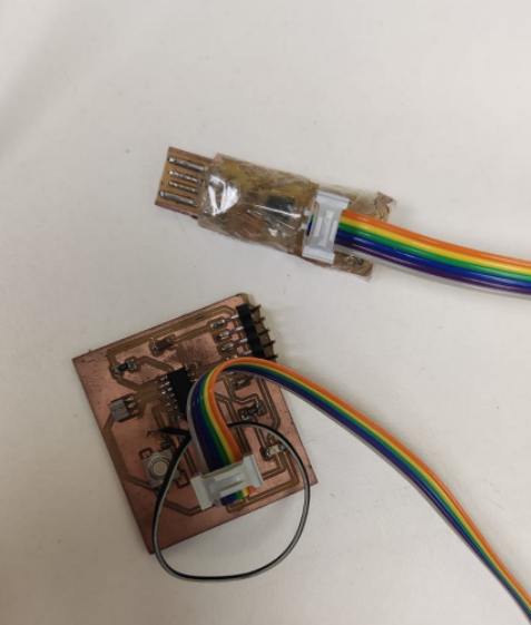
On my FabTinyISP I connected the ISP header to the corresponding header on the hello-world board.
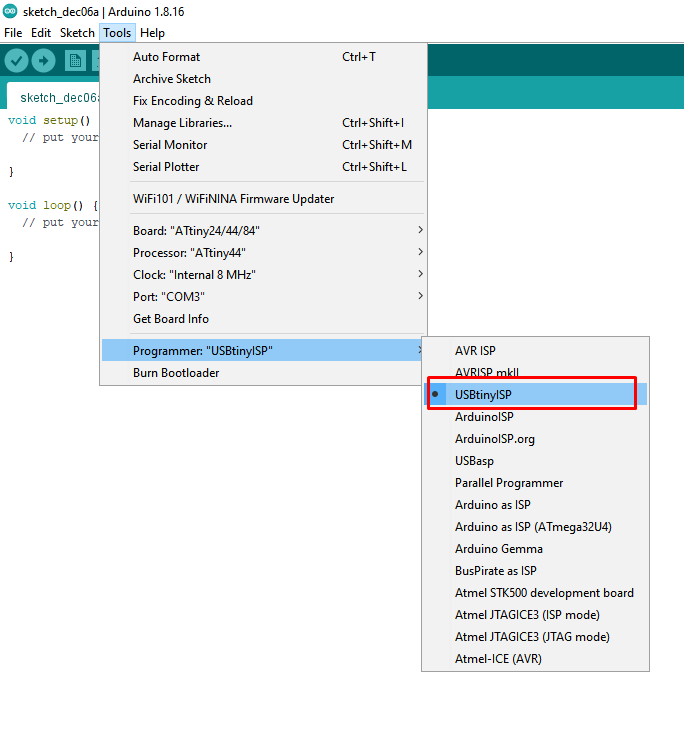
In the ArduinoIDE I chose the USBtinyISP as programmer
After This I plugged the programmer into the USB Port and with a click of Burning Bootloader the flashing process starts.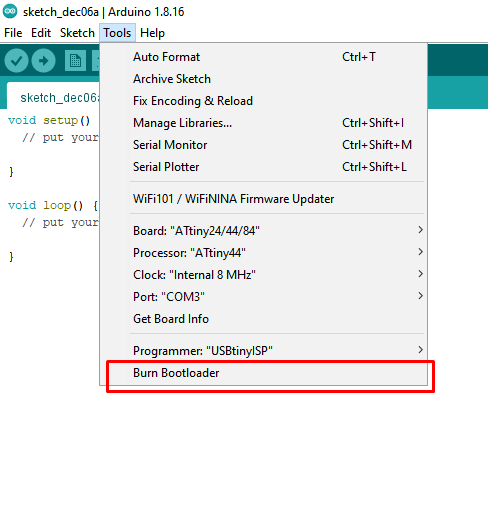
Flash At last
I did this whole excercise in the electronics production week
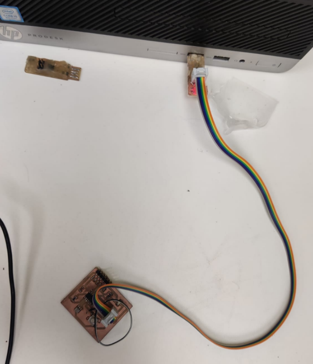
After this i programmed the PCB using the Fabisp programmer which i mage during the electronic production we
ek.I connected the fabisp to the hello echo board through the isp header cable.Check the cable whether it is properly oriented at both the ends and properly connected.
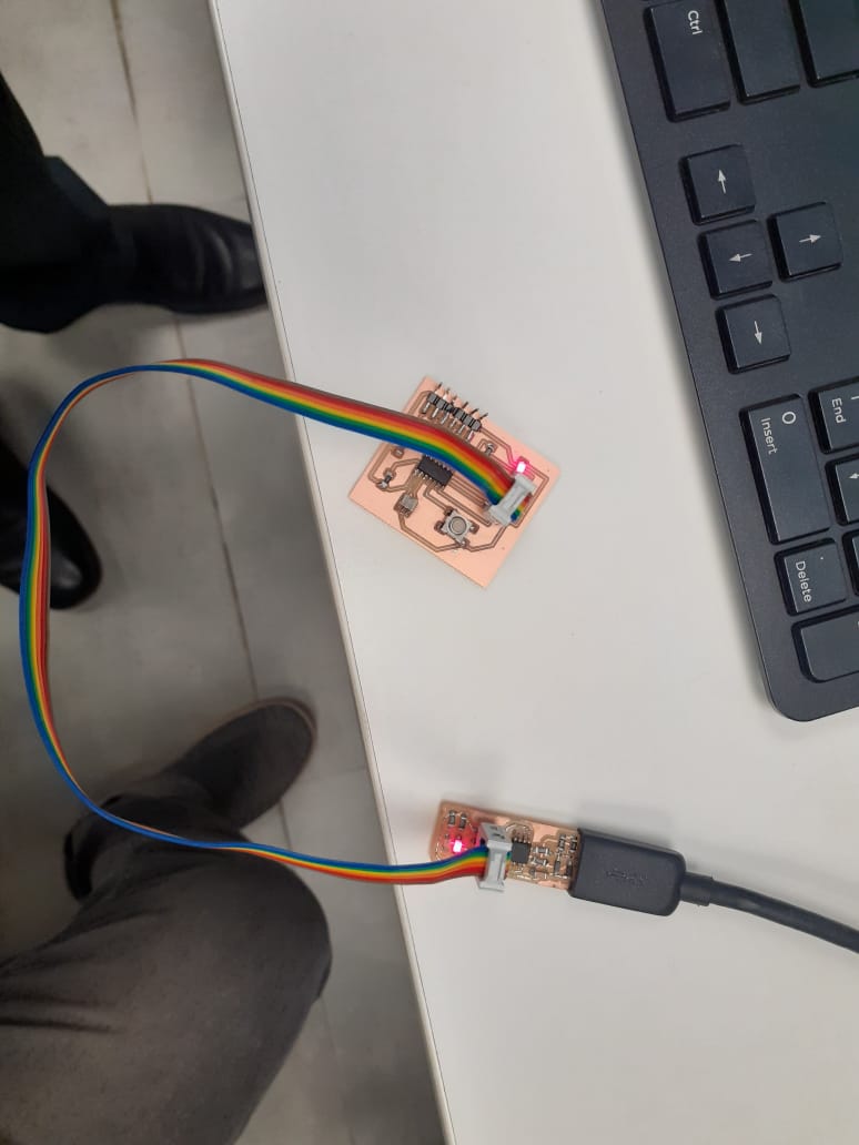
I was not aqainted wth the arduino programming i took the help of the instructor Mr.Sheebu.Who helped me in programming the pcb.
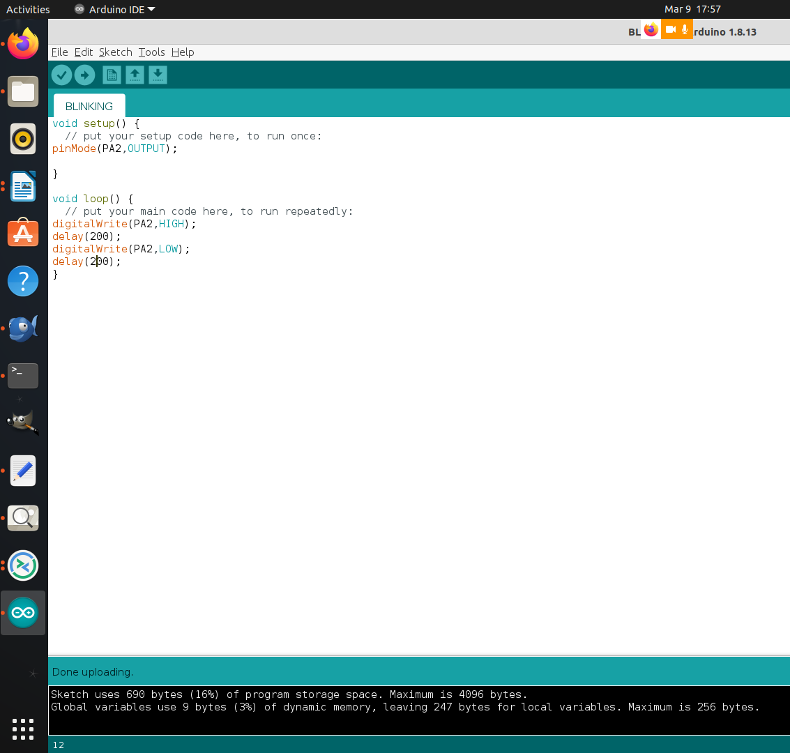
Here is the video of the programmed PCB
Credit:-https://in.tek.com
Th files of this week can be Downloaded here.