Electronics Production :-
This week Assignment was to make an in-circuit programmer that includes a microcontroller by milling and stuffing the PCB, test it,then optionally try other PCB processes.
In my lab i am having Monofab SRM-20 CNc Desktop Miller. 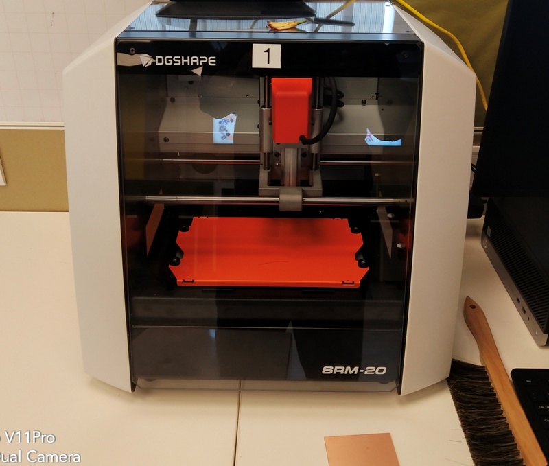
This week i had to :-
1)To mill out the PCB for the Fab ISP Programmer
2)Install the Required components on the PCB
3)Test the FabIsp programmer
5)Programm the PCB as an ISP Programmer
Getting Ready FAB ISP programmer (What is Fab ISP ?)
FabISP is an In circuit Serial Programming device designed in the FABlab for programming the other microcontrollers on the board which we are making.In This ISP we are using Atmel ATTiny-45 micro controller which is 4 K Byte of Memory where as Attiny 85 is 8k byte of memeory.
The pin configuration of Attiny 45 is :-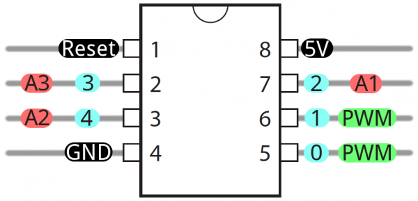
Setting up the Milling Machine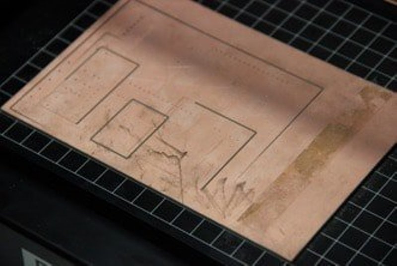
We are using the Monofab SRM 20 milling machine for designing the FabISP.
1) Setting Up the Sacrificial Layer
We will be using a copper clad board as our sacrificial layer.
We need a sacrificial layer here because in case something goes wrong and the milling
bit goes further than expected, we might just end up damaging the base plate.
The sacrificial layer as the name suggests sacrifices itself for saving the base plate from any damage.
To do this we apply the dual sided tape onto a copper clad board, about the same or of greater size to that of the plate we are going to mill. This would also help us when we are cutting the final board out. Make sure that when you place the board on the build plate you leave a 1 sqcm border. Make sure that the board is level and apply sufficient force above it to make it adhere to the base plate.
2) Setting Up the PCB Board for Milling
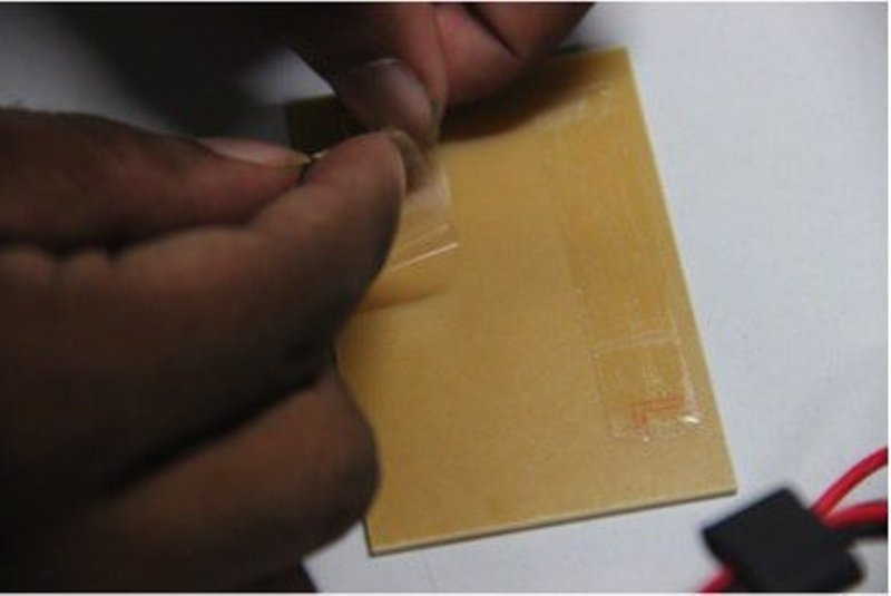
As we did before, apply the dual sided adhesive on the plate which is to be milled. Make sure that the adhesive is almost evenly placed so that the milling surface is level. Check out the figure below:
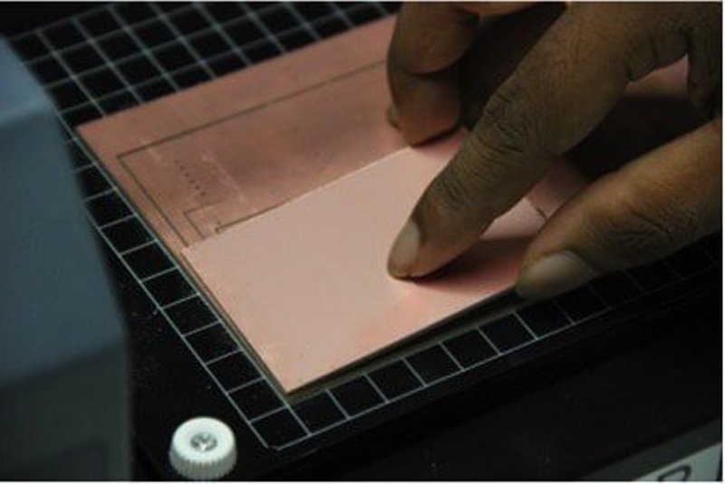
Now, place the board on the sacrificial layer, leaving a 1 sqcm border like before.
And now gently apply pressure on the board so that the board adheres to the sacrificial layer. Observe the milling surface to see if its level. If not try applying pressure gently on the raised areas, if that doesn’t work redo the adhesive part, making sure that its level and uniformly distributed. Once that’s done, your milling surface is ready.
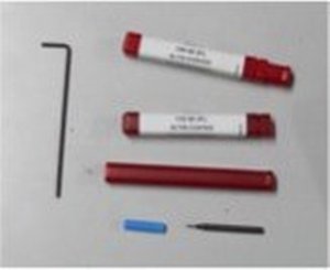
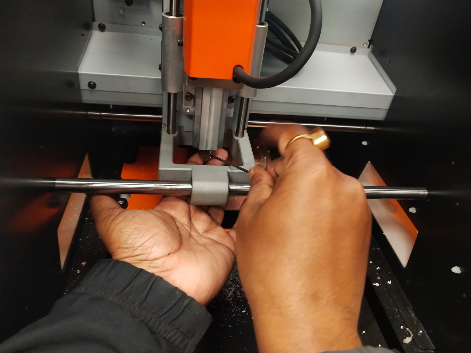
3)Attaching the Mill Bit to the PCB Miller
Depending on the type of cut you wish to make you will have to select from 2 available bits. 1/64 for the traces and 1/32 for the border cut. Make sure, while storing a bit, it should be placed in its appropriate container with the cap on.
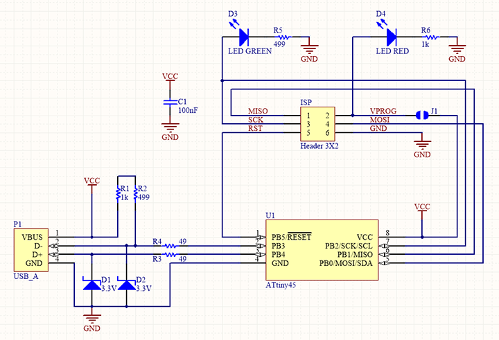
The circuit diagram for the FabISP is
Following is the Gerber file for the above circuit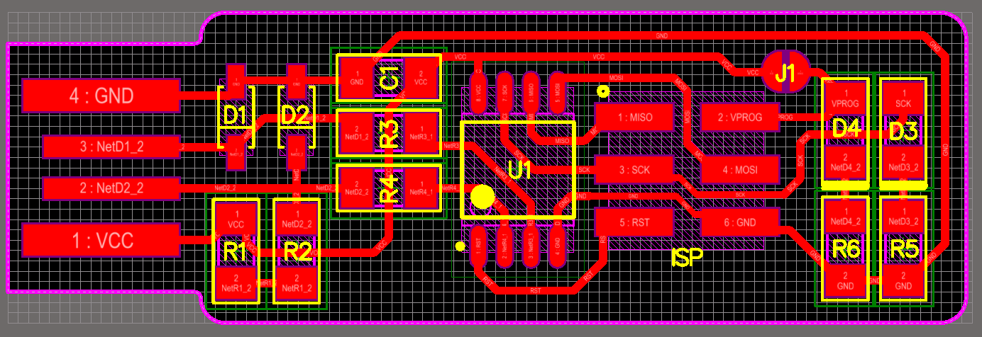
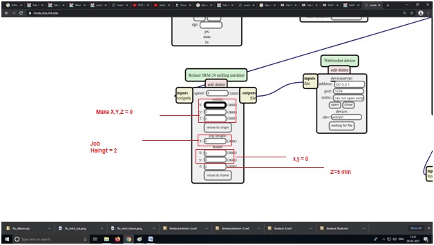
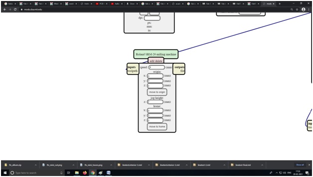
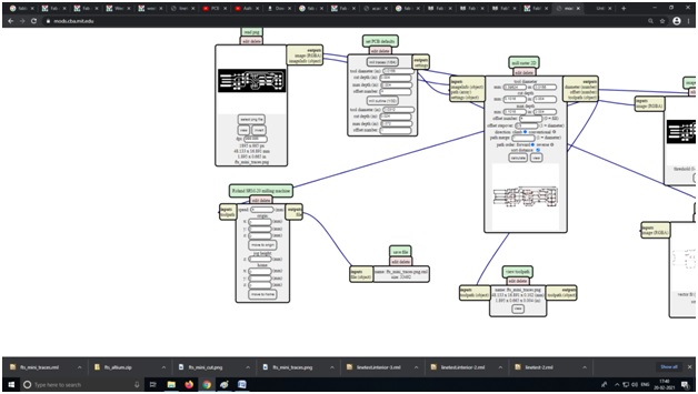
4) Now open https://mods.cba.mit.edu

Right click and select programs

select programs->open server programs->SRM -20->PCB PNG
make origin X,y,z cordinates to 0,0,0 job height 2 mm and home x,y to 0,0 and z to 5 mm.
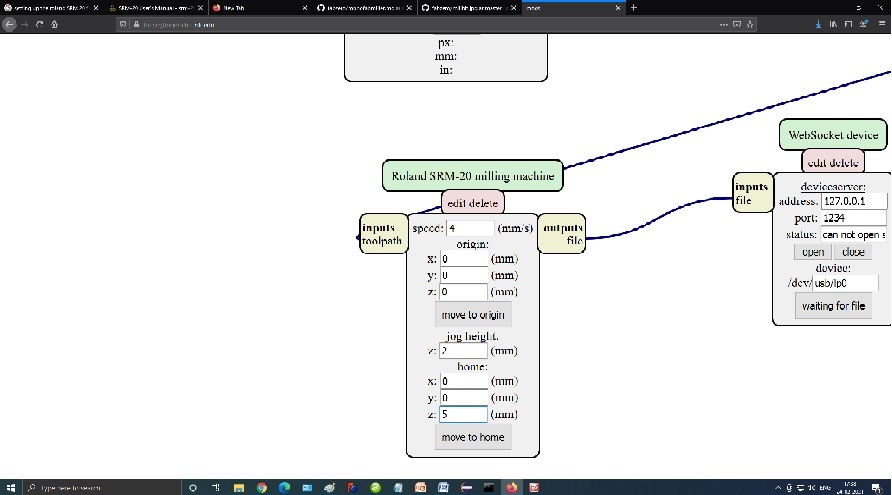
Delete the web socket device using right click over web socket device as our machine is locally connected to the desktop.
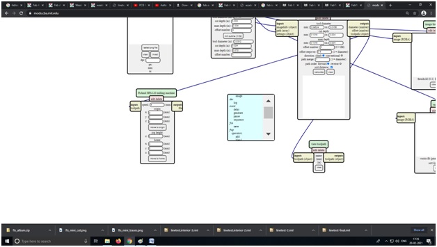
Now right click in place of the web socket device and select
modules->open server modules->file save->
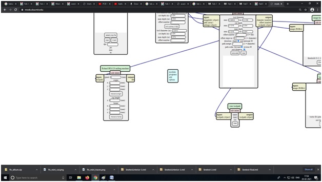
Now click on input file object and output file object to connect them.
Now click on 1/64 bit as we are now to mill the traces of our PCB and set offset to 4.
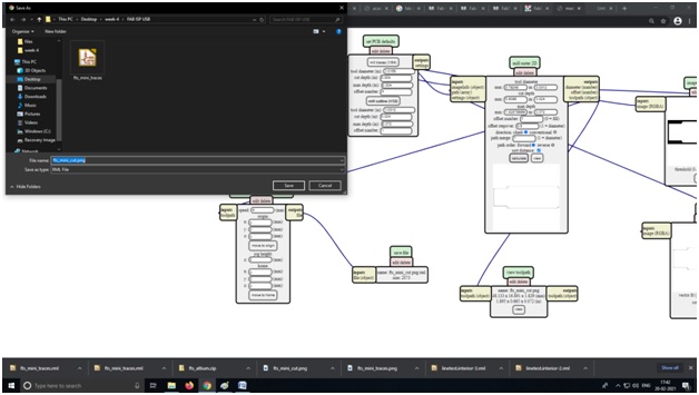
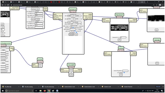
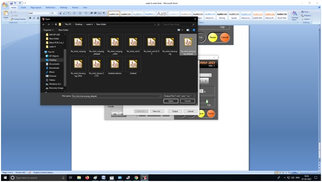
Now Select the png file with the trace path of the PCB(In my case fts_mini_tracesdeepak.png)
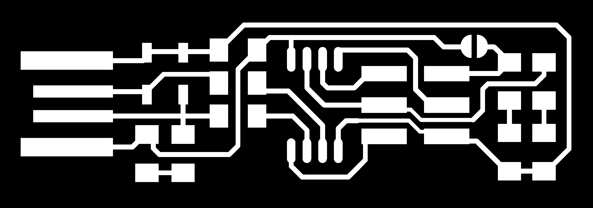
Select traces png file in the mods.
and press calculate in mods, which will give us the .rml file to be send to the Monofab SRM 20 to be milled.
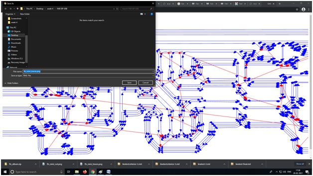
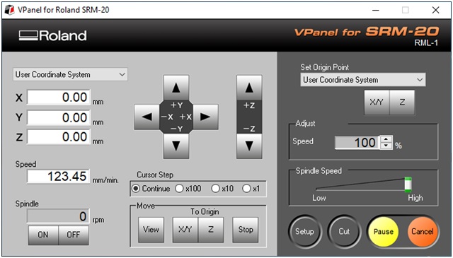
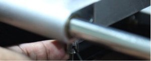
Now open the V panel and set the origin and of the monofab SRM 20 by pressing the
X Y for the location from where the job will start milling and set the z by holding the bit
And select the trace file as following:-
and the Roland SRM-20 will start to mill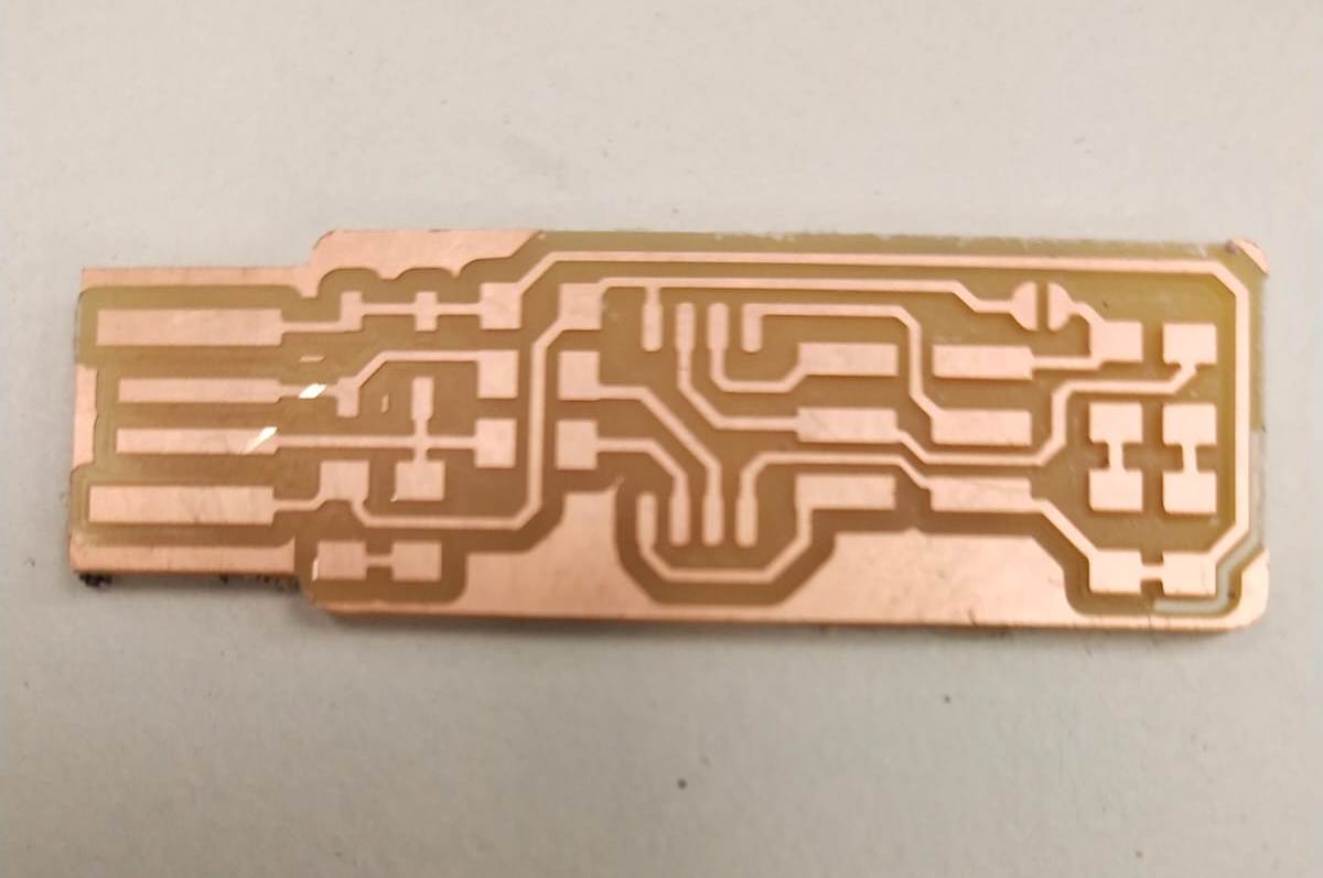
Video to be uploaded
Here is the Correct final Circuit Board we get

and for Cut Image do same but install 1/32 Bit in the milling machind and in mods select 1/32 and calculate and get the .RML file
In my case name was fts_mini_cut.png
and select the fts_mini_cut.rml file from vpanel
and the milling machine starts to cut the cut PCB out the PCB board and i get the following PCB
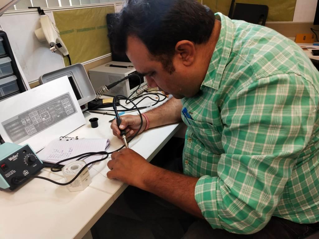
Now Soldering the components on the Fab USB ISP circuit board.
1) 1x ATtiny45
2) 2x 1k Ohm resistors
3) 2x 499 Ohm resistors
4) 2x 49 Ohm resistors
5) 2x 3.3v zener diodes
6) 1x red LED
7) 1x green LED
8) 1x 100nF capacitor
9) 1x 2x3 pin header
I took the components from the inventory and soldered on the PCB
Notice the Pin Configuration of Atmel ATTiny-45 Micro Controller
| Pin No | Function | Description |
| 1 | /RESET (controlled by RSTDISBL fuse bit) | Pin by default is used as RESET pin. The pin active low. PB5 can only be used as I/O pin when RSTDISBL Fuse is programmed. |
| 2 | XTAL1 - Crystal Oscillator input | CLKI(Clock Input from an External Clock Source ) |
| 3 | XTAL2 - Crystal Oscillator output | CLKO(The divided system clock can be output on this pin ) |
| 4 | 0V Ground Vdd | Connected to ground |
| 5 | MOSI - Master data Output / Slave data Input | MOSI (Master Output Slave Input). When controller acts as slave, the data is received by this pin. [Serial Peripheral Interface (SPI) for programming] |
| 6 | MISO - Master data Input / Slave data Output | MISO (Master Input Slave Output). When controller acts as slave, the data is sent to master by this controller through this pin. [Serial Peripheral Interface (SPI) for programming] |
| 7 | SCK - Serial Clock Input | SCK (SPI Bus Serial Clock). This is the clock shared between this controller and other system for accurate data transfer. |
| 8 | +5V Supply Vcc | Connected to positive voltage |
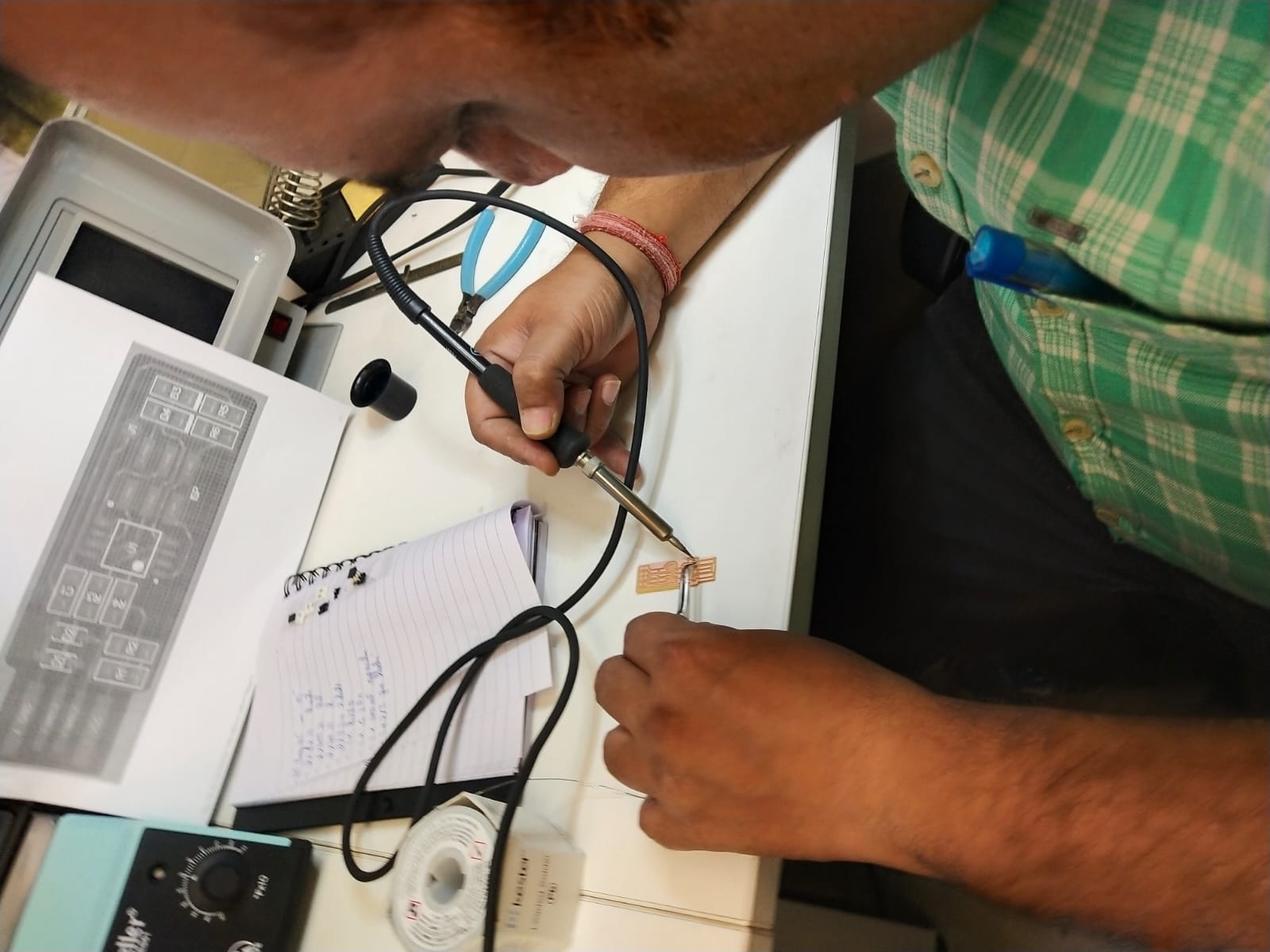
Here is the soldered PCB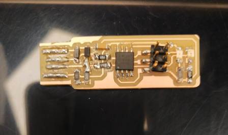
Remember to check the polarity of the LED and zener diode.
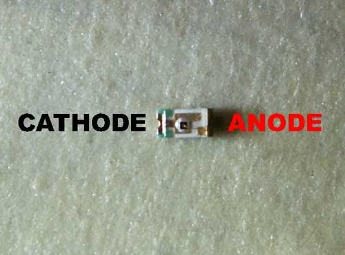
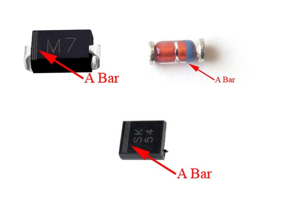
The A Bar indicated in the SMD Zener diode Image is Cathode.
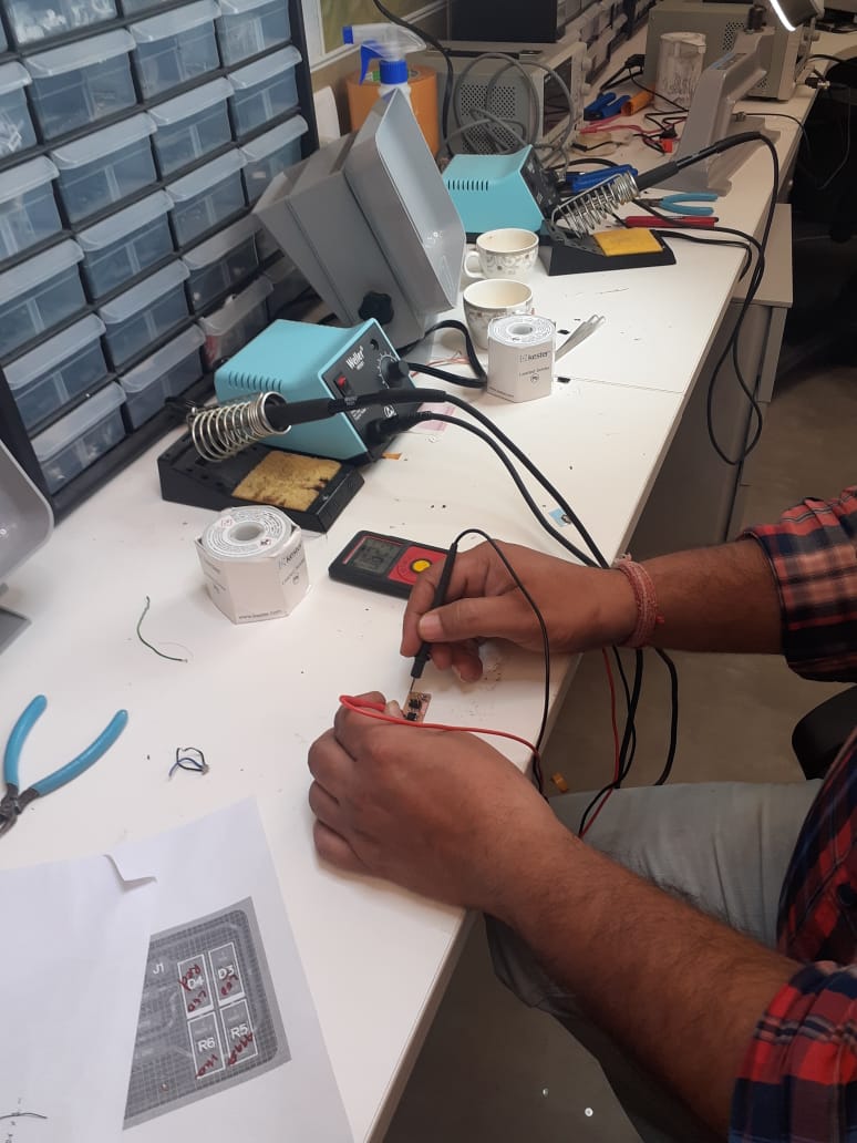
Now when i plugged in the USB ISB into the USB port of the PC the RED Led was not glowing.Then i checked the PCB with multi meter and found the 1 leg of the micro controller was not properly soldered.I soldered it again.
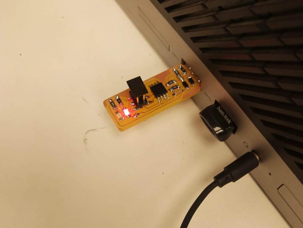
and again checked by plugging into the USB port of PC.
It Was Success.Till Now the PCB is OK.
Now the programming is to be done.I am using windows system but for programming i Ubuntu linux for programming....
Install Necessary Software for AVR Programming:
1) Avrdude (for programming AVR microcontrollers)
2) GCC (to compile C code)
Open terminal and type
sudo apt-get install flex byacc bison gcc libusb-dev avrdude
Then type
sudo apt-get install gcc-avr
Type "y" if asked
sudo apt-get install avr-libc
then type
sudo apt-get install libc6-dev
#####Download and Unzip the Firmware:
Move to desktop cd ~/Desktop
wget http://academy.cba.mit.edu/classes/embedded_programming/firmware.zip unzip firmware.zip
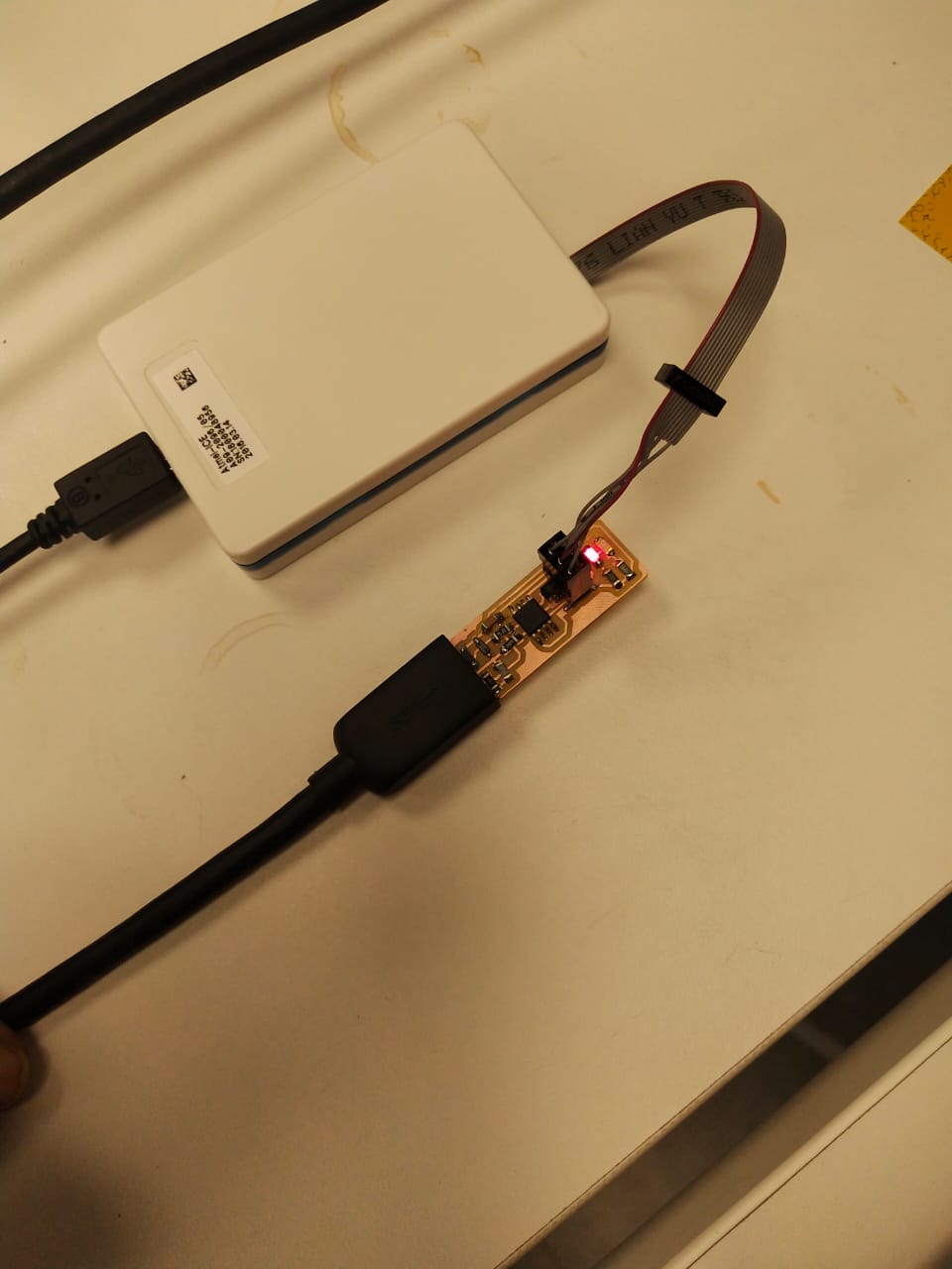
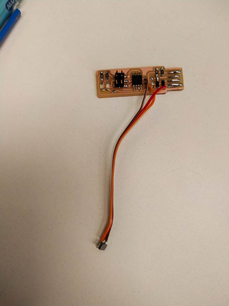
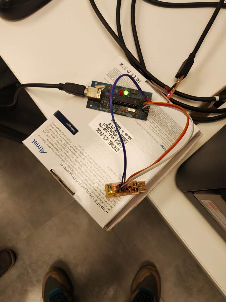
Power the FabISP Board
Connect the fab USB ISP to your pc to supply the power of 5v to the ISP board and attach another programmer like ATmel ac connected in picture
After this followed the tutorial of the fabacdemy
http://archive.fabacademy.org/archives/2017/doc/programming_FabISP.html
Go to the firmware directory and write
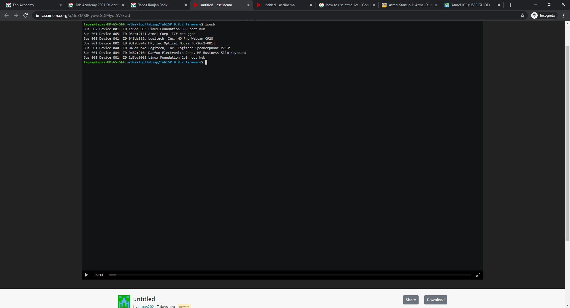
avrdude-c atmelice_isp -p t45 -v lsusb
it will show Atme ICE Debugger listed
Then type
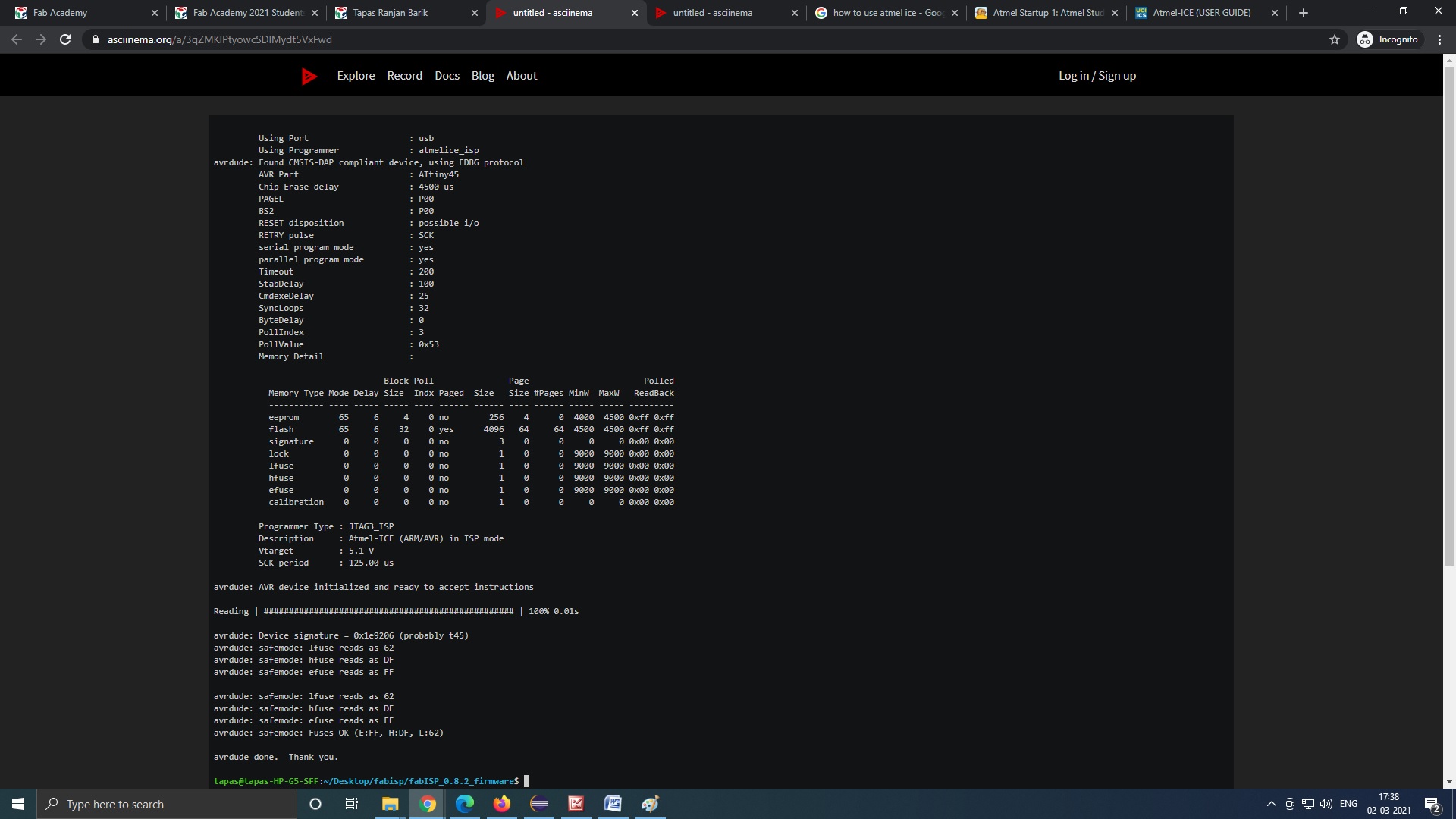
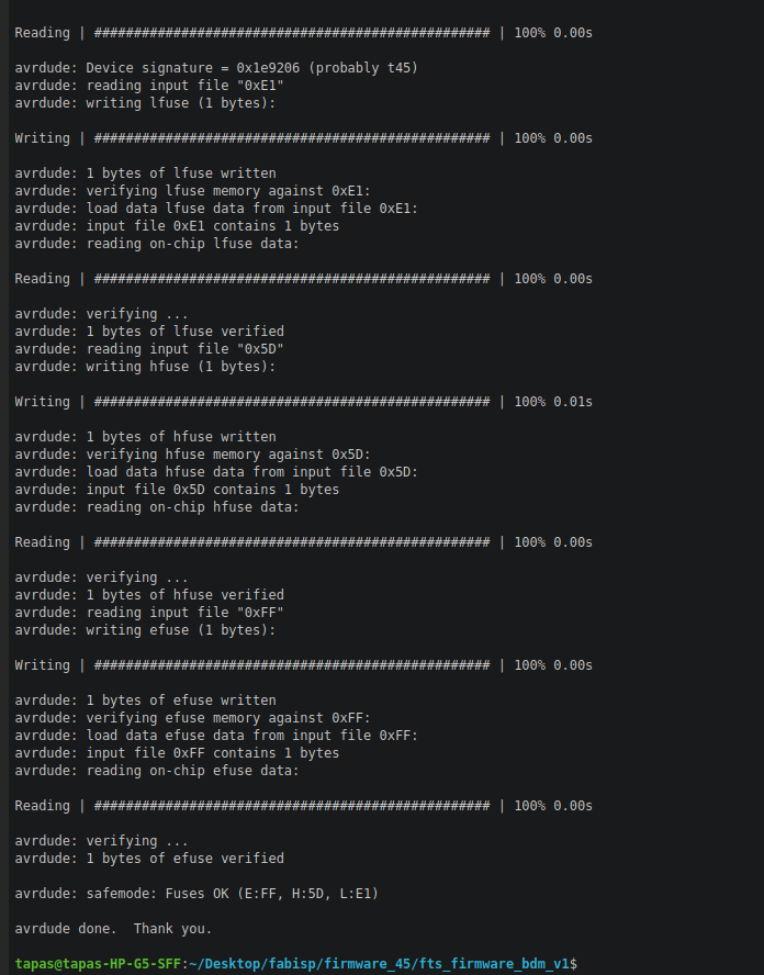
avrdude-c atmelice_isp -p t45 -v
reads the fuse bits

>make file
Makes the hex file
Then type
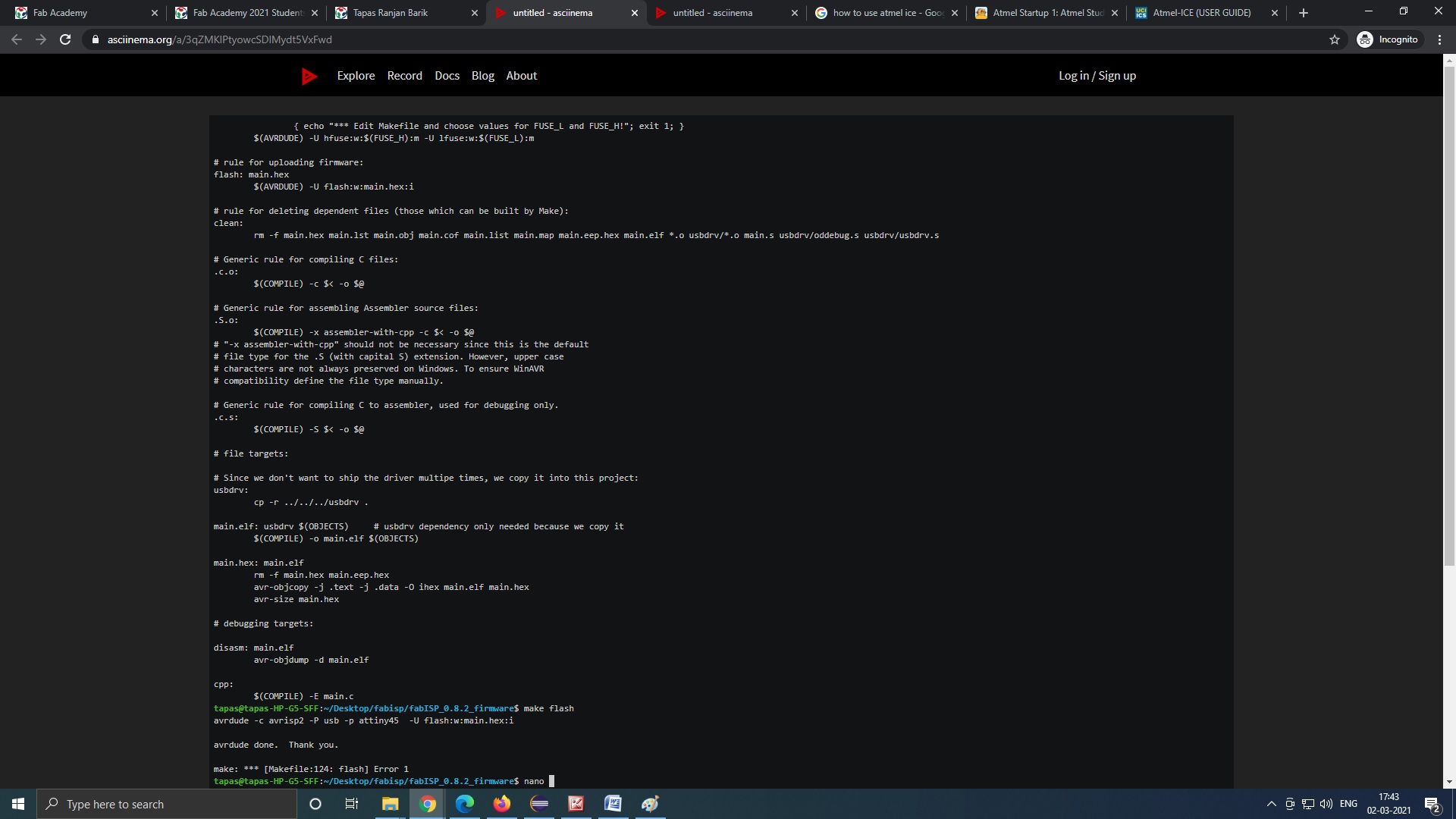
>make flash
here i got the error with atmel ice
Then we changed the programmer.our collegue had another AVR programmer to programm the Fab ISP and followed the whole excercise from the begining.
Type
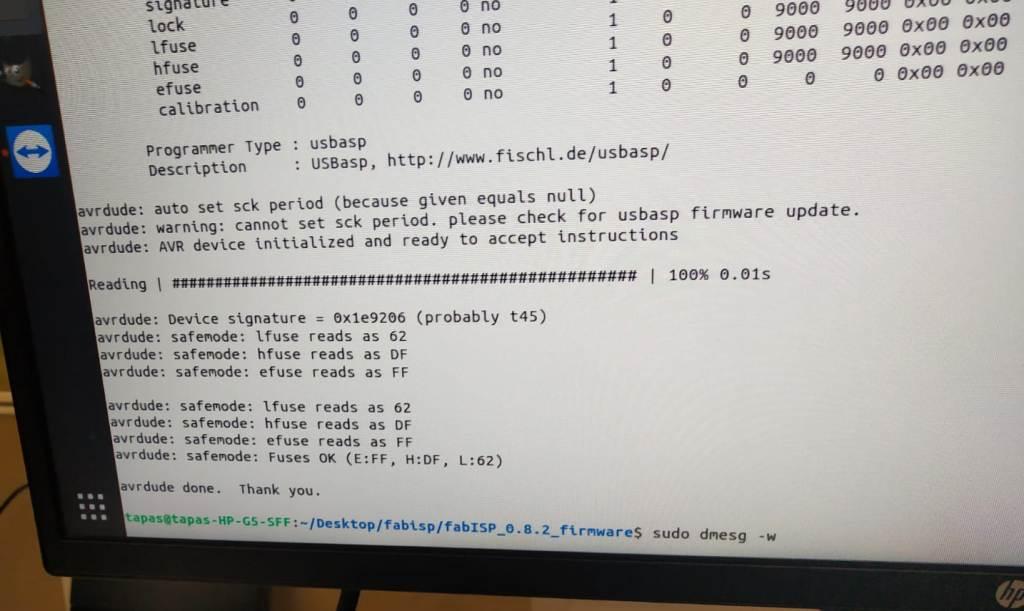
avrdude-c usbasp -p t45 -v
//(here i had made attiny44 to attiny 45 (t45))
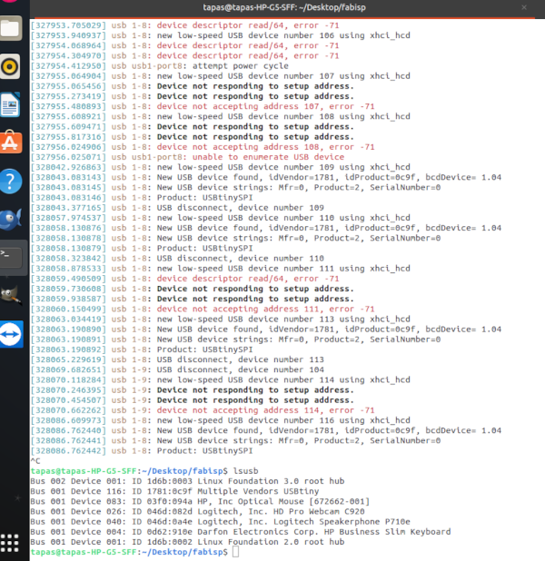
it was showing success but on plugging my FAB Isp to USB port of PC it was not detecting.
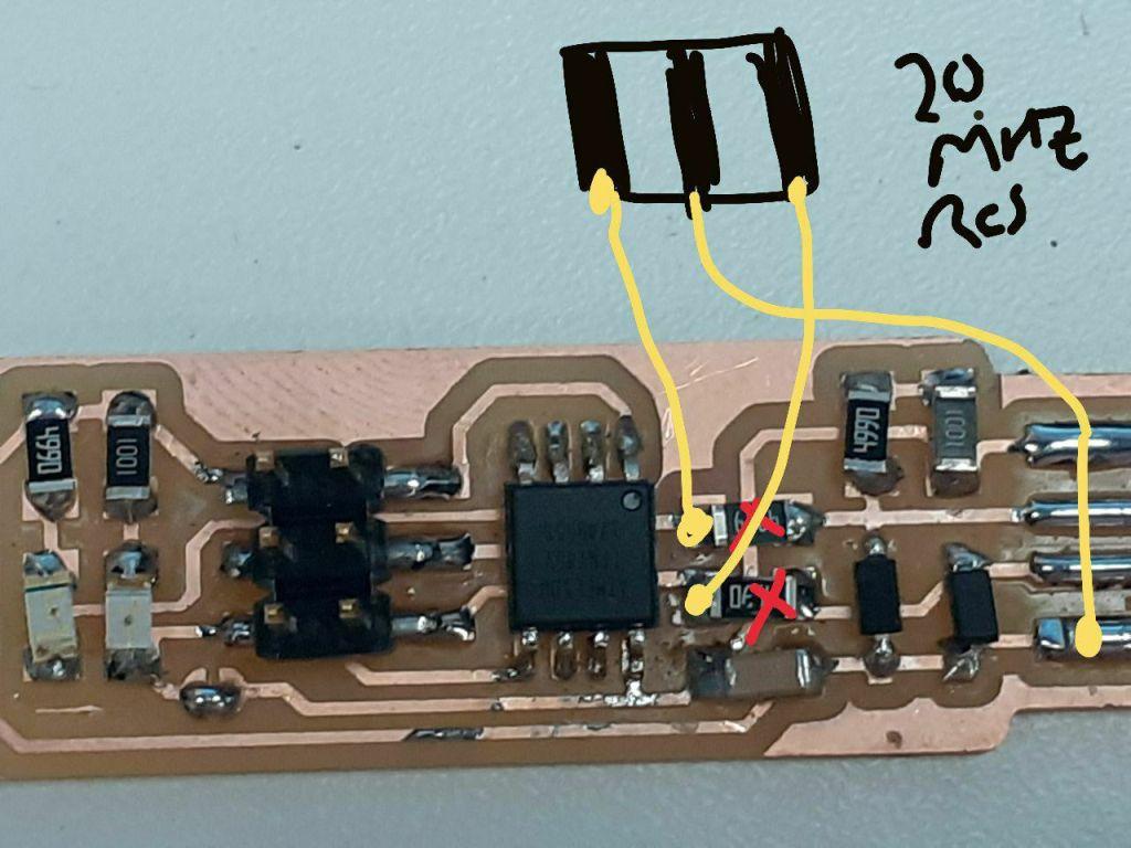
On sorting out the problem it was found that wrong firmware of attiny 44 was uploaded in our FAB ISP Attiy 45. So we downloaded the correct firmware.But our Instructor Mr.Sibu told that Now the firmware cant be over written in the same microcontyroller so either change the micro controller or reset the fuse.So I decided to reset the fuses.Fo this Mr.Sibu Instructyed to connect the 20 Mhz SMD Crystal Oscillator to Pin No 2 and Pin 3 and center conncetion to Pin 4(Ground) of Micro controller.For this i ahd to remove the two resistors from pin no 02 and 03 and connect thed oscillator.
Now i downloaded the corrcet firmware from
https://github.com/Academany/FabAcademany-Resources/blob/master/files/firmware_45.zip
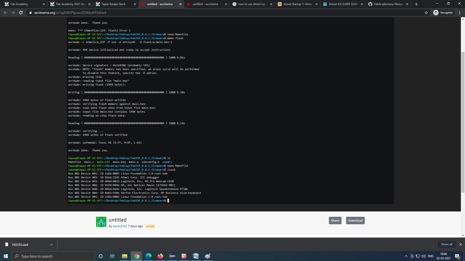
and did the same excercise and run the command with my Fabisp connected to the avr programmer belonging to Mr Debashish.
>rstdisbl
Now i disconncted the oscilltor and connected the resistors to the same pins of microcontroller. and followed the above steps to programm the FabISP connected to AVR programmmer. My programmer was programmed sucessfully.

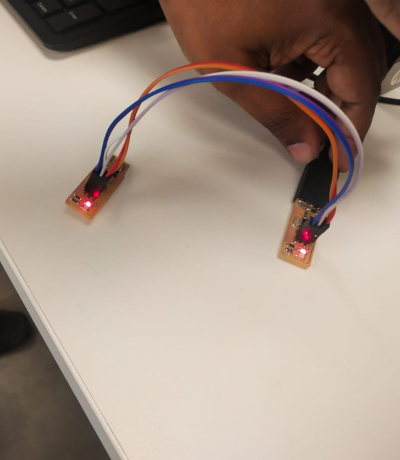
Then i used my ISP to programm the FABISP of my collegeue and type the command on my terminal from the firmware directory
>Avrdude -c usbtiny -p t45 -v
and next run the following command
>make flash
>make fuses
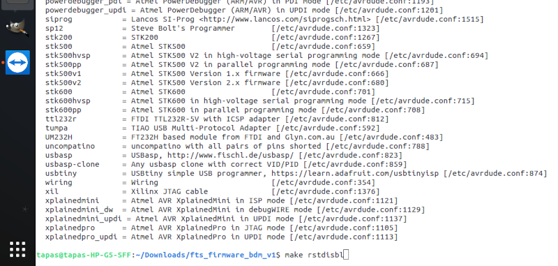
>make rstdisbl
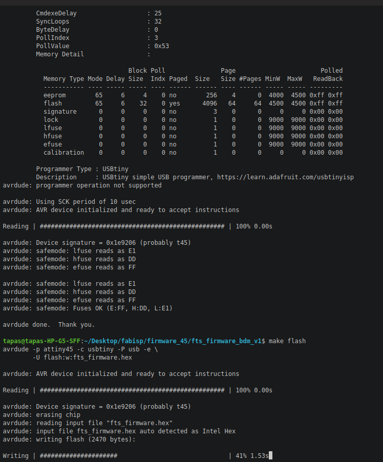
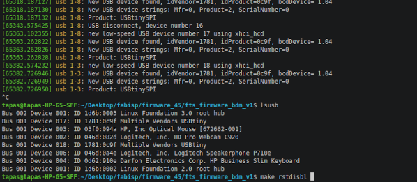
Here both The FabISP are being detected.
Here is the full video of the whole excercise
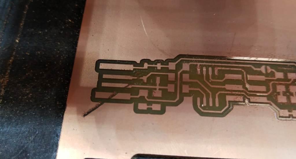
The Problem i faced during this excercise.I initially gave the i initially kept Z=2 mm insted of 5 mm,this was the result on the PCB.
This was the result.At the time when the milling of the traces was finished the bit was comming to its initial position,it came to its initial position cutting the trace path diagnally.I was worried why this happned.Me and my collegeua Mr.tapas discussed and told the problem to remote instructor Mr.Sheebu.He asked us to keep the job height to 5mm to that the milling bit could go to its initial position after finishing the trace path without touching the PCB.