Group Assignment
Test runout, alignment, speeds, feeds, materials, and toolpaths for your machine.
Individual Assignment
Make (Design + Mill + Assemble) something big.
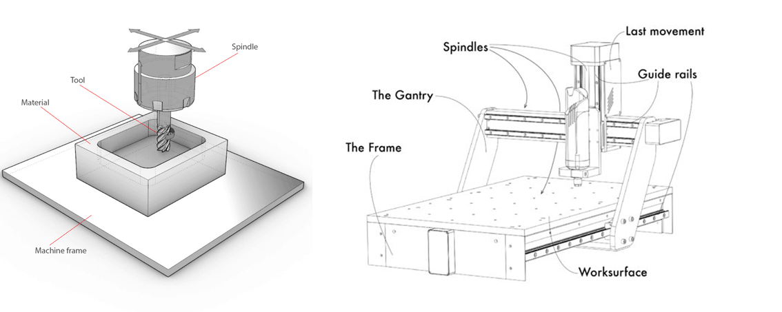
Introduction to CNC machines
The term CNC stands for Computer Numerical Control.
CNC machining is a subtractive manufacturing process which typically follows computerized controls codes and machine tools bits to remove layers of material from a stock piece known as workpiece.
This subtractive process is suitable for a wide range of materials: metals, plastics, wood, glass, foam, composites ...
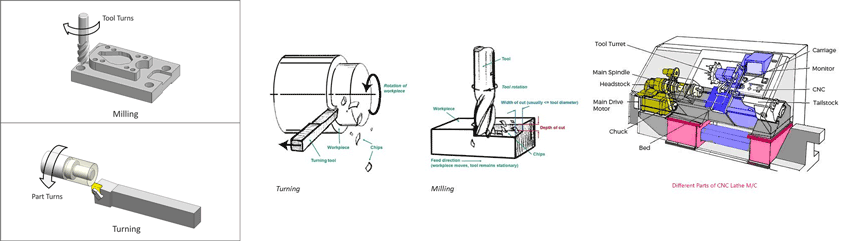
Types of CNC machining:
Milling
Milling is the process of cutting and drilling material.
CNC milling machines can have any number of axes (2 to 5) but are operated through a computer.
Turning
CNC Turning is a manufacturing process in which bars of material are held in a chuck and rotated while a tool is fed to the piece to remove material to create the desired shape.
Terms that should be understood before using any CNC machine:
- Types of Tools
- Difference between Feed and Speed
- Toolpaths
Tools
There are several types of tools that can be used depending on the job to be executed.
Two main types are: drill bits and end mill bits.
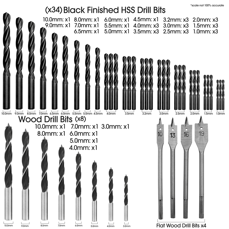
Drill bits:
Drill bits are cutting tools used to remove material to create holes, almost always of circular cross-section.
Drill bits come in many sizes and shapes and can create different kinds of holes in many different materials.
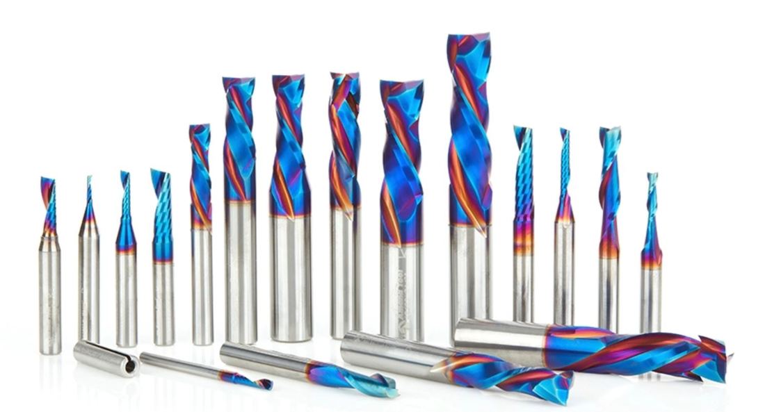
End Mill bits:
End mills are cutting tools that differ from drill bits in its application.
End mills can cut in radial direction and used for applications such as: profiling milling, tracing, face milling ...
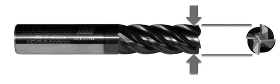
After checking the different types of bits what is important is to check the specs or anatomy of the bits:
Diameter, tooth, number of flutes, and the cut direction.
Diameter: is the dimension or diameter of the circle formed by the cutting edges as the tool rotates.
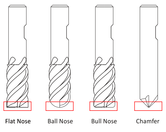
Tooth: is the head shape of the tool and it differs depending on the application to be used for.
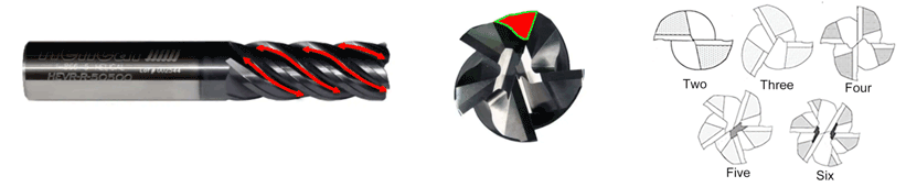
Flutes: is the cutting edge of the bit. Each bit has different number of flutes and also depends on the application.
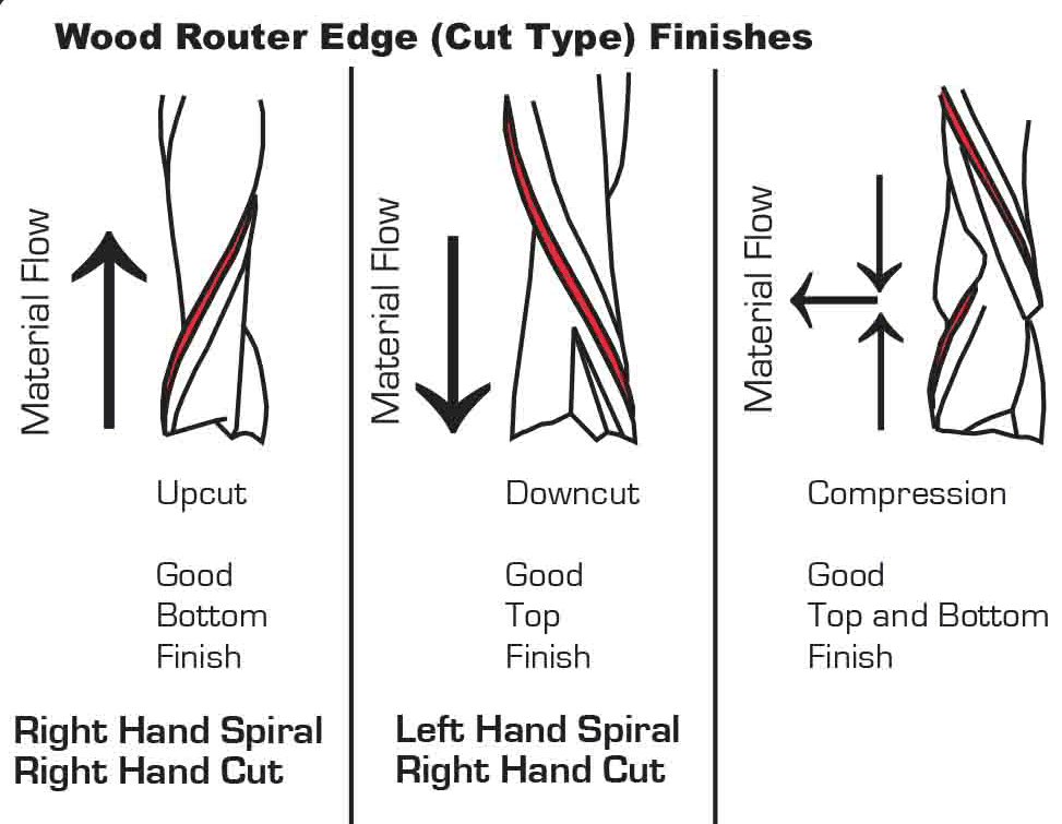
Cut direction: Each material has its own cut direction so we use different bits for each. Depending on which way the spiral goes on a cutter.
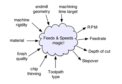
Spindle RPM and Feed Rate Calculations
To obtain a maximum machine performance, tool life and to have a balanced chip removal we have to calculate the cutting speed and feed rate of the machine.
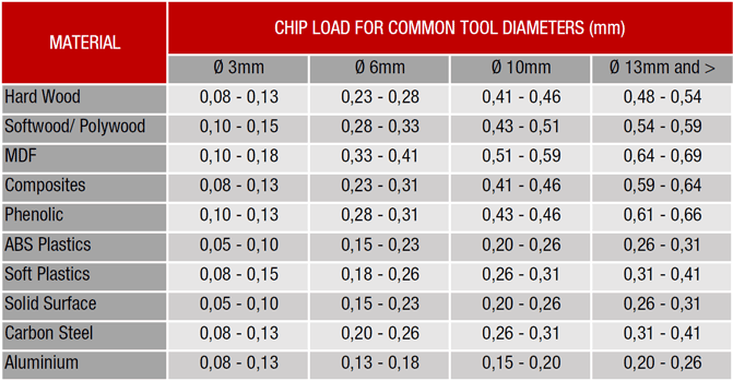
.Chipload chart:
The chip load is a term used to describe the thickness of a chip removed perpendicular to the cutting direction, measured vertically to the cutting direction.
The chip load is sometimes also referred to as "feed per tooth" and is calculated as follows:
The chip load is an important factor to determine the cutting speed and the feed rate.
A chip load that is too low causes too much heat on the cutting point.
A chip load that is too high is pushing the cutter through the material causing too much pressure.
We can say that:
The flutes of the end mill can determine the finishing effect of the material.
The more flutes we have we acheive a better result, but we have to be aware of the heat between the bit and material stock.
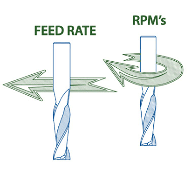
RPM and Feed Rate
RPM
RPM is the spindle speed and stands for Revolutions Per Minute.
When material is machined the cutter must revolve at a specific RPM and at a specific feed rate to achieve the proper chipload.
There are also several factors to be considered when choosing the proper RPM and feed rate.
Speed and feed rate will depend on the horsepower of the spindle.
While a high RPM will generally result in a higher quality finish, it can also result in higher friction that will, in turn, increase the wear on your bit.
Higher tool RPM produces smaller chips, while higher feed rates produce larger chips. Overall, if the chips are too large, your bit will be likely to break, but if your chips are too small (like fine powder), you will be dulling your bit. It’s all about getting the right balance.
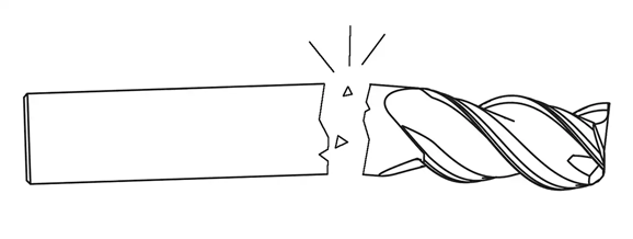
Running too fast or too slow can break your tool:
Running a tool too fast can cause big chip size removal or even catastrophic tool failure. Also, a low RPM can result in deflection, bad finish...
RPM is calculated using the following equation:
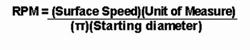
Surface speed = surface speed per minute is the measurement of the linear surface that travels past a given point with every revolution in one minute of time.
π = 3.14
Diameter = tool diameter
Obtained answer = RPM
Feed Rate
This measurement is how fast one moves the tool against the workpiece.
The feed rate used depends upon a variety of factors, including power and rigidity of the machine, rigidity of part hold-down, spindle horsepower, depth and width of cut, sharpness of cutting tool, design and type of cutter, and the material being cut.
Feed rate and spindle speed: Spindle speed that is too fast with a slow feed rate can result in burning or melting the material stock.
Spindle speed that is too slow with a faster feed rate can ruin the cutting edge, deflection of the end mill and possibility of breaking the end mill.
Feeding it too little or too much:
The best feed rate for a job varies by tool type and workpiece material. If you run your tool with too slow of a feed rate, you run the risk of recutting chips and accelerating tool wear. If you run your tool with too fast of a feed rate, you can cause tool fracture. This is especially true with miniature tooling.
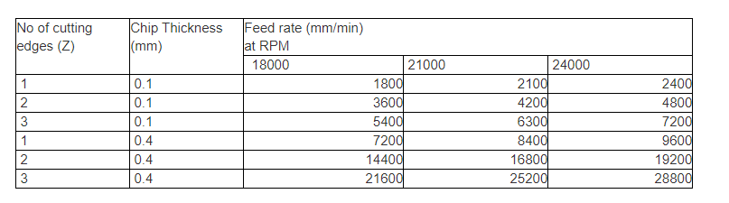
Feed rate is calculated using the following equation:
Feed = N x T x Z
N = number of cutting edges (flutes)
T= chip load (chip per tooth)
Z= RPM
Toolpath
Toolpath: This is a coded route that the CNC machine follows to cut. Think of it as a guide for the device. It is the intended trajectory that the tip of the endmill will follow, to remove material and produce the desired geometry of the workpiece.
2D toolpaths known as 2.5D correspond to cutting a 2D feature in the design, moving only two axes of the machine at a time.
3D toolpaths correspond to cutting a 3D feature, and potentially moving the three axes of the machine simultaneously.
Settings that control the toolpath:
Ramp: Ramping can be used to lower the strain on the tool when plunging into the material. When ramping is activated, the tool will go down at an angle and not straight down in Z as it normally does.
Ramping involves moving a mill along two axes the z-axis and one of the x or y axes.
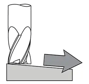
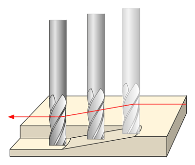
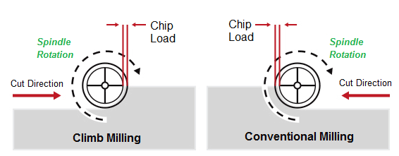
Toolpath direction: There are two distinct ways to cut materials when milling: Conventional Milling and Climb Milling.
Climb Milling = Down Milling
Conventional Milling = Up Miling
These two techniques are related to the rotation of the cutter and the direction of feed.
Conventional milling: the cutter rotates against the direction of the feed.
Climb milling: the cutter rotates with the feed.
Group Assignment
Here you can find our group assignment LINK
Test I
Test I was done using the ShopBot CNC Router
Cutting Table: (X) 1524 mm x (Y) 2440 mm.
Software used: VCarve
We used 10 mm MDF for our tests with 6 mm bits.
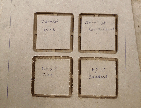
Part I:
In this test, we used an up-cut 2-flute bit, and a down-cut 2-flute bit, and we tested both for conventional and climb paths.
We noticed that the down-cut bit had a smooth finish at the top, but the bottom had rough edges.
The up-cut bit gave opposite results to the down-cut bit, with the bottom having the smoother edges.
We did not notice any difference between climb and conventional cutting in our test.
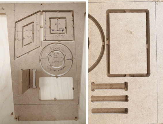
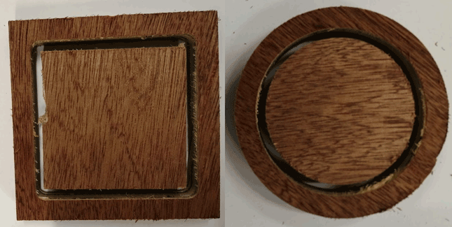
Part II
In the second part, we designed a 100 x 100 mm square, with a smaller square inside of it 60 x 60 mm, and a circle of diameter 100 mm with a smaller one inside of diameter 60 mm.
We measured the dimensions after cutting, the results for the square shows that there is a 0.75mm difference in the X-direction, and a 0.4mm difference in the Y-direction.
The results of the circle shows that there is a 0.75mm difference for the outer circle, and a 0.34 mm difference for the inner one.
We also tested T-bones with different depths, it is not possible to fit our piece in the slot without T-bones.
Test II
Test II was done using the AXYZ CNC Machine
Cutting Table: (X) 1524 mm x (Y) 2440 mm.
Software used: RhinoCAM
We used 18 mm plywood for our tests with 5 mm bits.
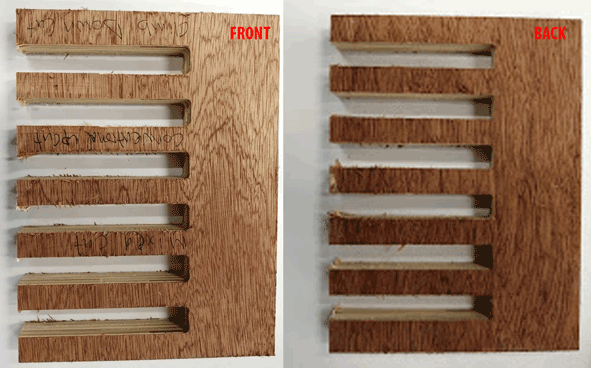
Part I:
In this we checked the different cutting directions found in RhoCAM the climb toolpath down cut mill, conventional toolpath upcut mill, and mixed toolpath.
The results shows that the mixed cutting between climb and conventional has a better result than the other options.
The mixed option in RhinoCAM alternates the cutting direction between each parallel plane.
Part II:
In this test we designed a 100 x 100 mm square, with a smaller square inside of it 70 x 70 mm, and a circle of diameter 100 mm with a smaller one inside of diameter 70 mm.
The results for the squares after cutting were the same dimensions and we didn't need to adjust anything in the file.
The result for the circles the 100 mm after cutting were 98 mm and the 70 mm were 69 mm.
As a result we need to increase the diameters by 1 or 2 mm.
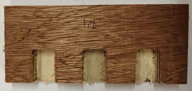
Part III:
In this test we tried the pocketing option the rectangles are 30 x 20 mm and after cutting the result was 28 x 18 mm.
As a result we need to increase the dimensions in the file 2 mm from each side to have perfect results.
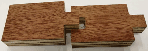
In this test the openings are 20 x 20 mm and after cutting we had the same results but the joint didn’t fit so we need to increase the dimensions of one side by 1 or 2 mm.
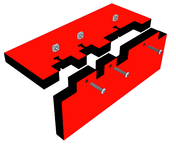
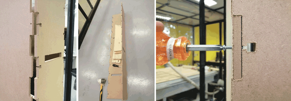
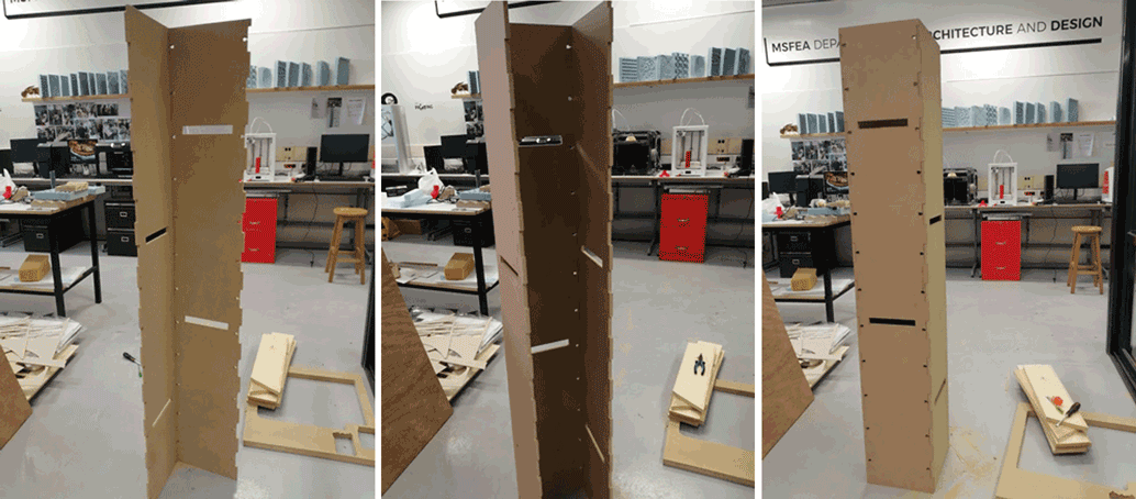
DESIGN
For this assignment I decided to start designing my final project structure using corner L joints.
The structure is divided into four parts with slots to hang the pots.
Design and Drawing Steps:
I used rhinoceros 3D modeling software to draw the structure with the joints.
Each side of the structure is 170 x 28 cm.
In the structure we have two types of grooves.

First two sides the dimensions of the openings are rectangles with 7 x 1 cm (thickness of the wood) with 1 mm rounded corners because I will be using the 2 mm router bit.
Second two sides the dimensions of the openings are also rectangles with 7 x 1 cm in addition to a square of 1 cm and a 4 mm rectangle for the screw to connect both parts. I will be using a 4 mm diameter screws.
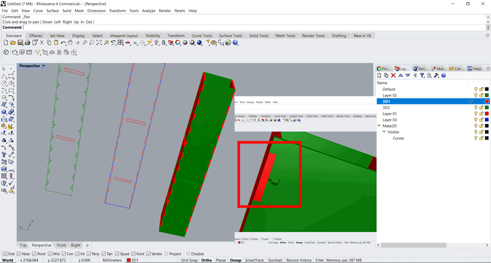
I started by drawing the file in 2D with the exact dimension before extruding each side alone and building it in 3D.
Some of the commands that used are polyline, trim, offset, fillet, extrudecrv, BooleanDifference etc...
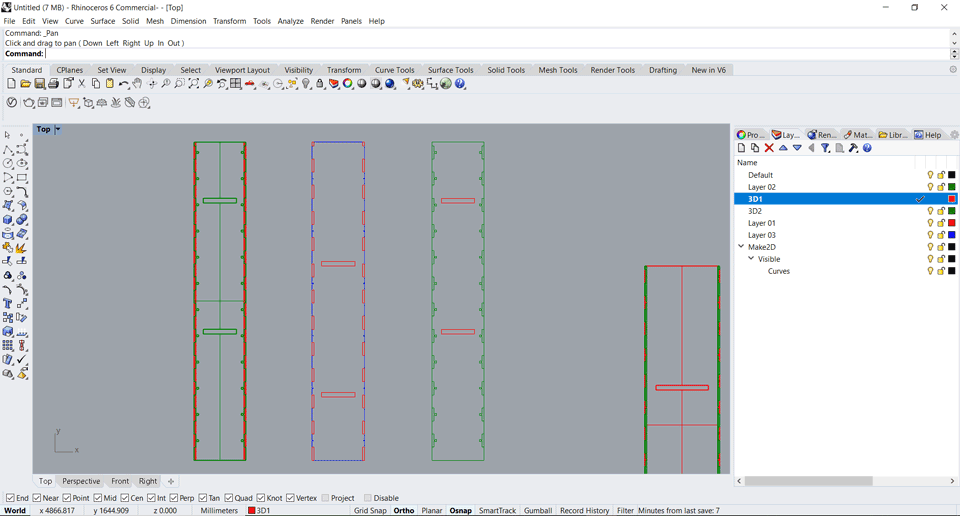
After checking all the dimensions I prepared the file for the cnc machine.
I drew a rectangle 2440 x 1220 mm (the wood board size) and placed the parts inside the stock board.

The 2D parts should be only 2D polylines. 2D cut parts should have each part represented as a single closed curve or polyline. So I used the commmand join for all the parts.
I made sure that my lines meet exactly at endpoints and there are no duplicate, intersecting, or overlapping lines.
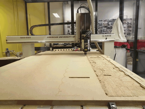
CNC router and RhinoCAM software
The CNC router that I will be using is AXYZ 4008 ATC.
ATC is Automatic Tool changer option that comes with some machines.
The tool cabinet has a space for seven tools.
Cutting Table: (X) 1524 mm x (Y) 2440 mm.
Can be used for: Routing and engraving in 2D and 3D on all woods and plastics.
For the cnc router we have a vacuum pump Becker connected to the table channels and dust extractor HOLZPRO connected to the cnc head.
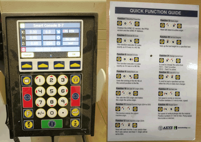
After putting the wood board on the router there are some functions I used to load the tool from the tool cabinet, calibrate the tool I will be using, calibrate the material with the tool and assign the user origin.
Using the control panel the functions are:
F32 for loading the tool from the tool cabinet.
F25 for tool calibration with the machine sensor.
F20 for material calibration with the tool.
F10 for assigning the user origin.
RhinoCAM
RhinoCAM is a CAM Software plug-in that runs completely inside of Rhinoceros. RhinoCAM includes modules for MILL, TURN, NEST and ART.
After opening the rhino file click on RhinoCam tab and select mill option then a panel will open on the left side.
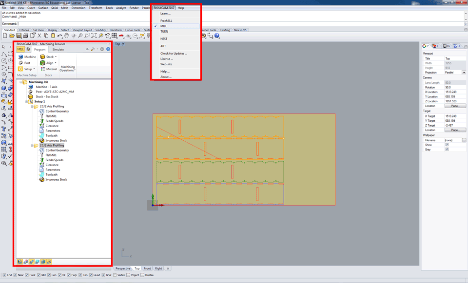
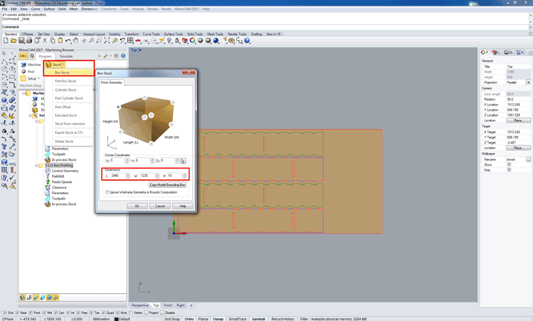
Then select stock - box stock and a panel will open in the diemnsions insert the L W H of the material you want to use on the cnc machine and a brown rectangle will appear on the screen.
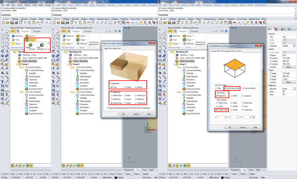
In the Align tab click on align stock a new panel will open in the Z alignment select top and XY alignment to south west.
In set world coordinates system a new panel also will open select set to stock box - zero face highest Z and in zero postion select south west.
In the machining operations select 2 axis then profiling option.
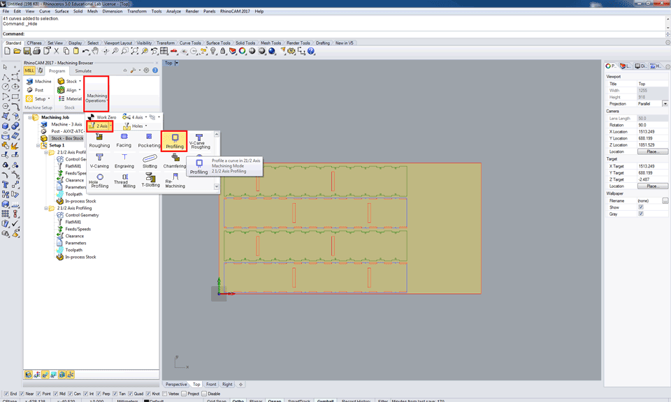
After the selecting the operation it will appear on the left side with a set of settings to be chosen and selected.
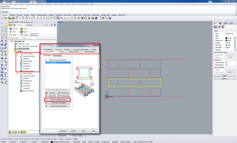
When we right click on the operation a panel will open first we have to choose the control geometry that are the polylines that we want to cut. click on select curve / edge regions and select the curves on the screen.
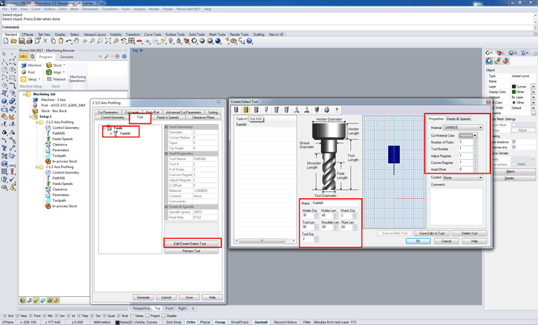
Second step is to choose the type of tool we want to use flat mill, ball mill, chamfer mill. Then click on edit/create/select tool option and a new panel will open with the settings we will put the numbers related to the bit we want to use and its number in the machine tool cabinet.
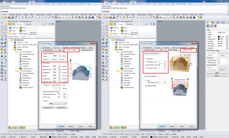
Now we will move to the feeds and speeds section in the spindle parameters we will add the rpm and direction of cut according to the material to be used and the calculations done with respect to the tool diameter. The cnc that I will be using has a cnc motor of max 24000 rpm.
In the clearance plane we will choose the clearance plane definition the maximum Z height above the stock that the bit will follow while moving from part to another without hitting the material.
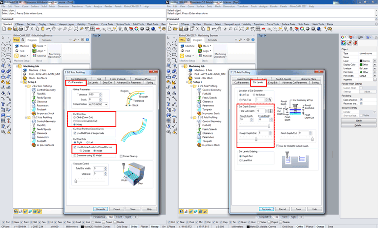
In the cut parameters we will choose the cut direction between the three options that we have: climb down cut, conventional up cut, and mixed cut.
Then we will choose if we want an outside or inside cut.
In the cut levels section cut depth control we will add the total depth thickness of the material or if we want to cut less than the total thickness, rough depth, finish depth, rough depth/cut meaning that how deep we want to cut each level because sometimes we need to divide the total cut to several steps so we don't break the bits and ruin the material especially when using hard stocks like wood.
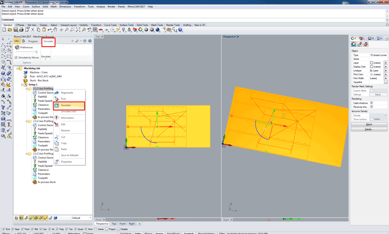
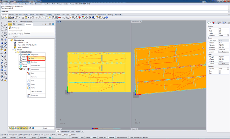
These were the important options that we always change. In the final step after adding all the settings we click on generate then on the left panel right click on simulate to check the file before creating a Gcode.
After the simulation is done now it's time to create a Gcode right click on the 2 1/2 axis profiling and select post.
Now we have a Gcode with all the settings.
Below is an example of a Gcode.
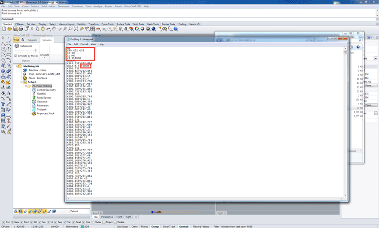
First five line include the below commands:
G90 meaning absolute programming all coordinates and movement values will be at 0,0.
G21 meaning that the programming or file is in mm.
G55 is the user origin we add it manually to the Gcode and on the machine by using function 10.
T1 is tool number 1 in the tool cabinet the machine will automatically read T1 and load the tool and S18000 is the spindle speed or rpm.
F1800 is the feed rate.
Then we have the XYZ coordinates for the entire file.
Milling Process and Assembly
The machine is connected to the computer through the network and we use an IP address to send the Gcodes to machine through A2MC software.
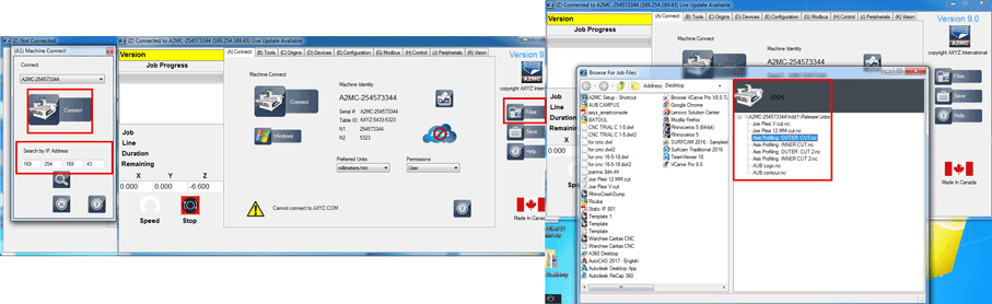
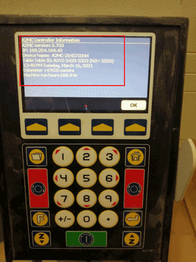
Using the function 01 on the smart console you can find the IP address of the machine to use it on the A2MC software to connect it.

This work is licensed under a Creative Commons Attribution-NonCommercial-ShareAlike 4.0 International License