10. Input devices
1. Group assignment.
1. probe an input device’s analog levels and digital signals
So lets start simple with a digital and analog sensor:
Pushbutton
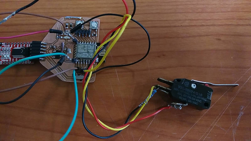
We attached an external button as a first input. Here we attached it to GPIO5 of the ESP. We only had to adjust the button pin in my first test code.
/*
  Based on the ESP8266 Blink by Simon Peter
  Blink the red LED(pin 13), and green LED(pin 12) alternating.
  Build in pushbutton on pin 14on the ESP-01 module
  This example code is in the public domain

*/
int ledGreen = 13;
int ledRed = 12;
int buttonPin = 5;
int buttonState = 0;
void setup() {
  pinMode(ledGreen, OUTPUT);     // Initialize the LED pin as an output
  pinMode(ledRed, OUTPUT);     // Initialize the LED pin as an output
  pinMode(buttonPin, INPUT); //initialize button pin as input
  Serial.begin(9600);
}

// the loop function runs over and over again forever
void loop() {
  digitalWrite(ledGreen, HIGH);   // Turn the LED on (Note that LOW is the voltage level
  digitalWrite(ledRed, LOW);   // Turn the LED on (Note that LOW is the voltage level
  // but actually the LED is on; this is because
  // it is active low on the ESP-01)
  Serial.println("low");
  delay(1000);                      // Wait for a second
 digitalWrite(ledGreen, LOW);  // Turn the LED off by making the voltage HIGH
  digitalWrite(ledRed, HIGH);   // Turn the LED on (Note that LOW is the voltage level
  Serial.println("high");
  delay(500);                      // Wait for two seconds (to demonstrate the active low LED)

  buttonState = digitalRead(buttonPin);

  // check if the pushbutton is pressed. If it is, the buttonState is HIGH:
  if (buttonState == HIGH) {
    // turn LED on:
    digitalWrite(ledRed, LOW);
    Serial.println("btn high");
  } else {
    // turn LED off:
    //digitalWrite(ledGreen, LOW);
      digitalWrite(ledRed, HIGH);
    Serial.println("btn low");
  }
}
This also went well. We also connected a multimeter to measure the on-off state of the button
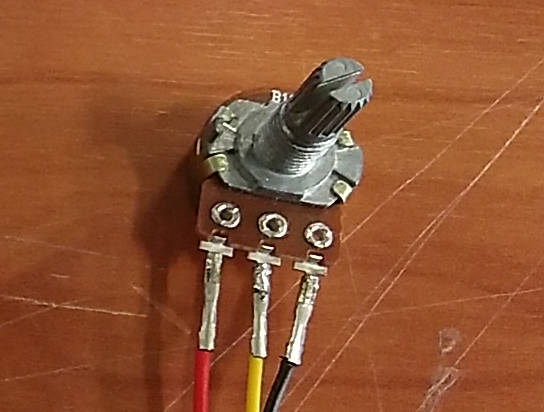
Potentiometer
Next is an analog sensor, the potentiometer would be one of the simplest to start with The signal or measuring pin of the potentiometer is in the middle. The other ones are connected to VCC and GND
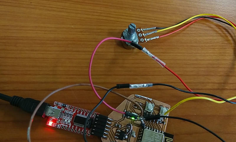
For this we used the analoginoutserial example from the arduino examples. we adjusted the code to have the LED on pin 12 and the potmeter on A0 This code read the sensor, that gives a value between 0 and 1023 and then it maps it to a value for the PWM of the LED, so the potmeter can adjust the brightness of the LED
// These constants won't change. They're used to give names to the pins used:
const int analogInPin = A0;  // Analog input pin that the potentiometer is attached to
const int analogOutPin = 12; // Analog output pin that the LED is attached to

int sensorValue = 0;        // value read from the pot
int outputValue = 0;        // value output to the PWM (analog out)

void setup() {
  // initialize serial communications at 9600 bps:
  Serial.begin(9600);
}

void loop() {
  // read the analog in value:
  sensorValue = analogRead(analogInPin);
  // map it to the range of the analog out:
  outputValue = map(sensorValue, 0, 1023, 0, 255);
  // change the analog out value:
  analogWrite(analogOutPin, outputValue);

  // print the results to the Serial Monitor:
  Serial.print("sensor = ");
  Serial.print(sensorValue);
  Serial.print("\t output = ");
  Serial.println(outputValue);

  // wait 2 milliseconds before the next loop
  delay(2);
}
2. Designing a new board.
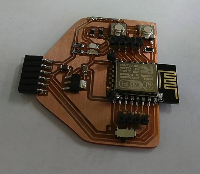
For this assignment we need a board that has inputs available. My previous board didn’t have any available pins broken out to connect sensors. To be a bit futureproof I thought it best to design a board with lots of headers to connect different stuff. I still want to work with wireless communication also, so I want to stick to the ESP range. Eventually I would like to make an ESP32 board, but starting a little smaller I will go with the ESP12-E for now. It will have wifi and lots of GPIO and protocols available to connect inputs and outputs.
https://randomnerdtutorials.com/esp8266-pinout-reference-gpios/
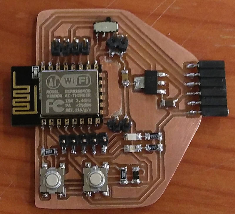
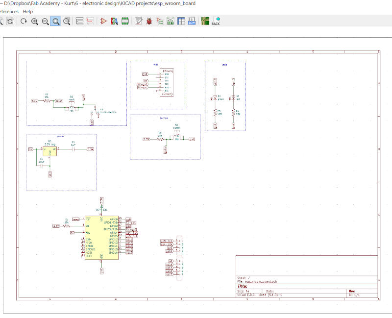
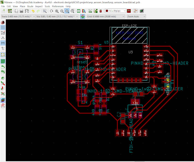
1. design of the board in Kicad
I first looked up the datasheet for the ESP-12E modules I have. ESP12E datasheet
To have better understanding of what pins needed to be connected and what power to provide everything. I used the same 3.3V regulators as previous design and added button to reset and a switch to put GPIO2 in programming mode. I also added some LEDS and an extra button.
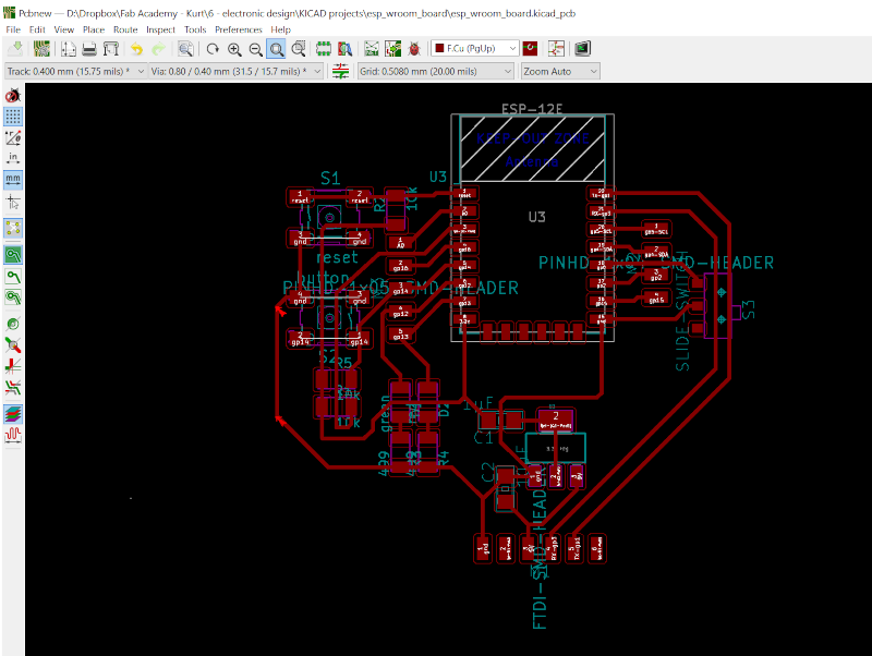
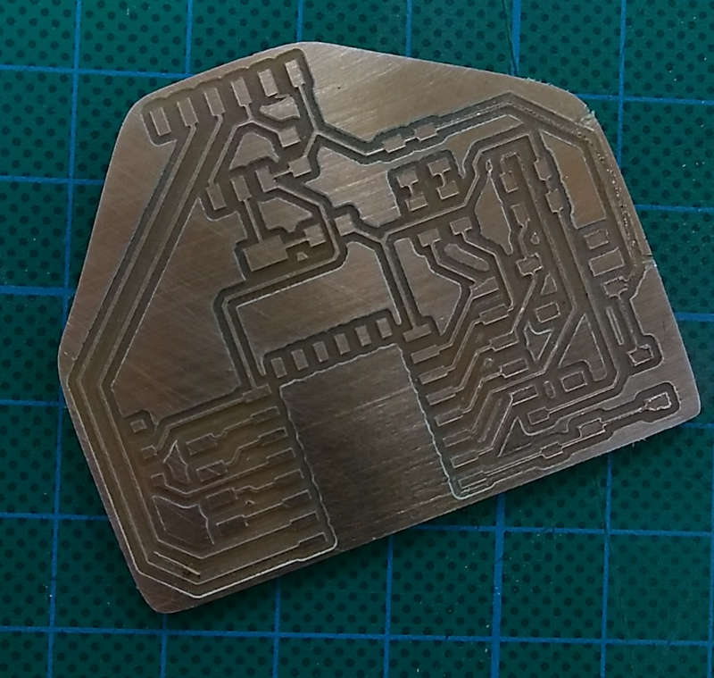
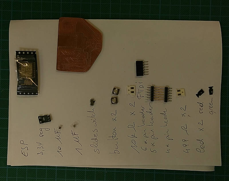
2. Milling and stuffing the board
3. first try out programming
Something is wrong. AGAIN!!!! It took me several hours of probing and measuring points on the board to finally find the main error. Capacitor is in the wrong place! I have to redo the board.
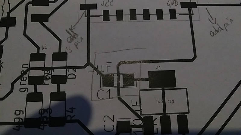
But I also already frankensteined an extra pin for ground and 3.3V. I thought I could better try to re-solder the capacitor. 1 pad could still be used and the other end I soldered straight on the GND trace. That seemed to get me a better reading and worked. I soldered a small jumper wire between the 2 pads to reconnect the now broken trace.
Now the esp chip has the correct power.
Now the trick and fiddling with getting the correct pins HIGH or LOW at the moment of booting to be able to flash the chip. I found this table in the ESP-12E datasheet
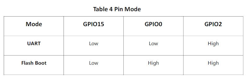
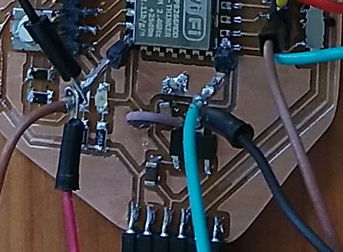
I had already added a sliding switch to put GPIO0 to Low, but not an option to put it High. I also did not add options or buttons to put GPIO15 and GPIO2 to Low or HIGH. So I soldered an extra jumper wire from 3.3V to the not connected in of the sliding switch. No I can change GPIO0 from Low to High by sliding the switch. So far so good. Since I already had header pins for GPIO2 and GPIO15, I also added an jumper wire from 3V to GPIO2 and a jumper from GND to GPIO5.
Now I can try to see if I can program this board. I SHOULD HAVE READ THE DATASHEET A LOT BETTER BEFORE DESIGNING THE BOARD
4. Next programming attempt
I have a red LED on pin 12, a green LED on pin 13 and a button on pin 14 I programmed the board to blink the leds alternating and send serial data to the pc to see when the button is pressed.
/*
  Based on the ESP8266 Blink by Simon Peter
  Blink the red LED(pin 13), and green LED(pin 12) alternating.
  Build in pushbutton on pin 14on the ESP-01 module
  This example code is in the public domain

*/
int ledGreen = 13;
int ledRed = 12;
int buttonPin = 14;
int buttonState = 0;
void setup() {
  pinMode(ledGreen, OUTPUT);     // Initialize the LED pin as an output
  pinMode(ledRed, OUTPUT);     // Initialize the LED pin as an output
  pinMode(buttonPin, INPUT); //initialize button pin as input
  Serial.begin(9600);
}

// the loop function runs over and over again forever
void loop() {
  digitalWrite(ledGreen, HIGH);   // Turn the LED on (Note that LOW is the voltage level
  digitalWrite(ledRed, LOW);   // Turn the LED on (Note that LOW is the voltage level
  // but actually the LED is on; this is because
  // it is active low on the ESP-01)
  Serial.println("low");
  delay(1000);                      // Wait for a second
 digitalWrite(ledGreen, LOW);  // Turn the LED off by making the voltage HIGH
  digitalWrite(ledRed, HIGH);   // Turn the LED on (Note that LOW is the voltage level
  Serial.println("high");
  delay(500);                      // Wait for two seconds (to demonstrate the active low LED)

  buttonState = digitalRead(buttonPin);

  // check if the pushbutton is pressed. If it is, the buttonState is HIGH:
  if (buttonState == HIGH) {
    // turn LED on:
    digitalWrite(ledRed, LOW);
    Serial.println("btn high");
  } else {
    // turn LED off:
    //digitalWrite(ledGreen, LOW);
      digitalWrite(ledRed, HIGH);
    Serial.println("btn low");
  }
}
This worked!
3. Sensors = Input
1. GPS
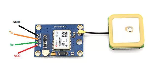
I want to us a GPS and had a cheap module from amazon based on the NEO-6M GPS chip from u-blox .
I also found some tutorial here https://create.arduino.cc/projecthub/ruchir1674/how-to-interface-gps-module-neo-6m-with-arduino-8f90ad
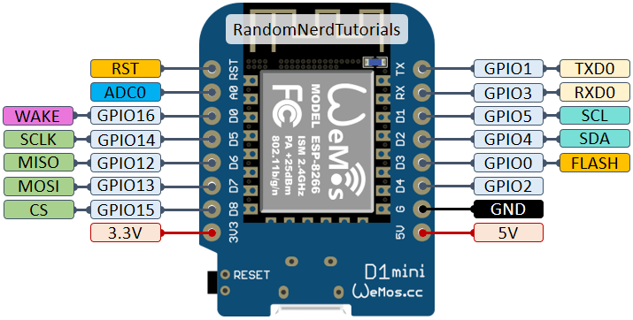
I tried with the Wemos D1 mini module, which I have and also uses the same ESP12 chip as I want to use. I thought I could use this one to test some code if my own board did not work. So I have it as backup. I had these boards for a while in one of my arduino parts bins
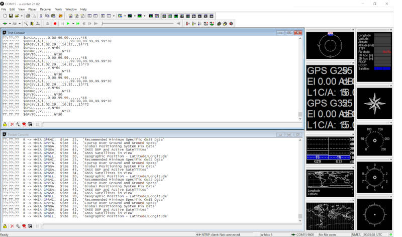
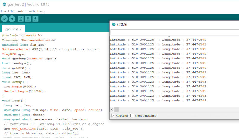
I followed the tutorial and nothing happened. I also don’t really know if there is a way to see if the module is working or not. So I have to dig around on the interwebs some more. Update: I tried 2 of the same modules, it seems they don’t work. I also connected with FTDI to some test software from U-blox, and it was also not able to give me a fix or some data. Also none of the modules shows any LED lighting up. So I think they were DOA.
I found an old GPS module from Skylab, that works on 5V. I connected it with the same board and code as I did the NEO6 modules. This one did give me a good fix and some data output.

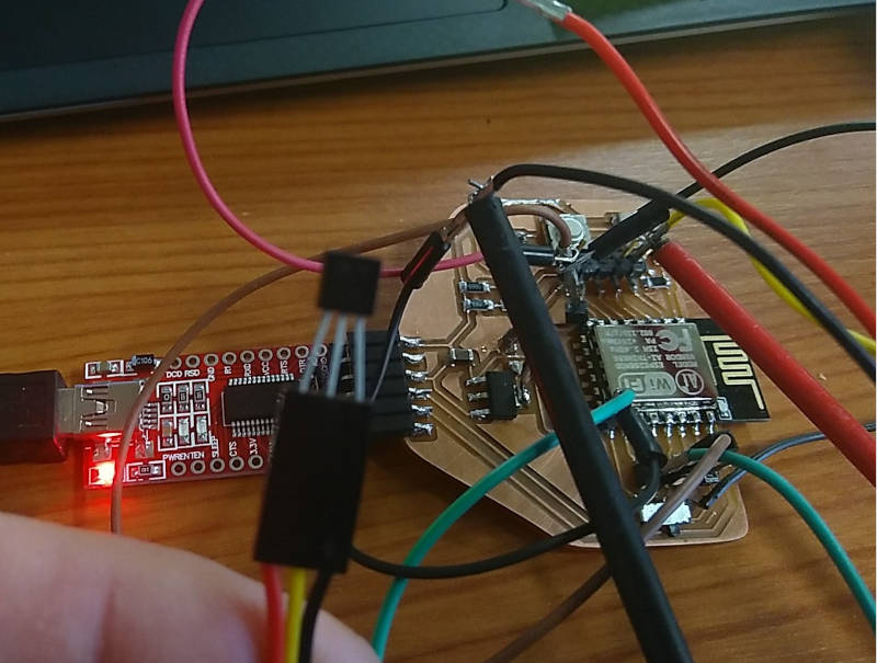
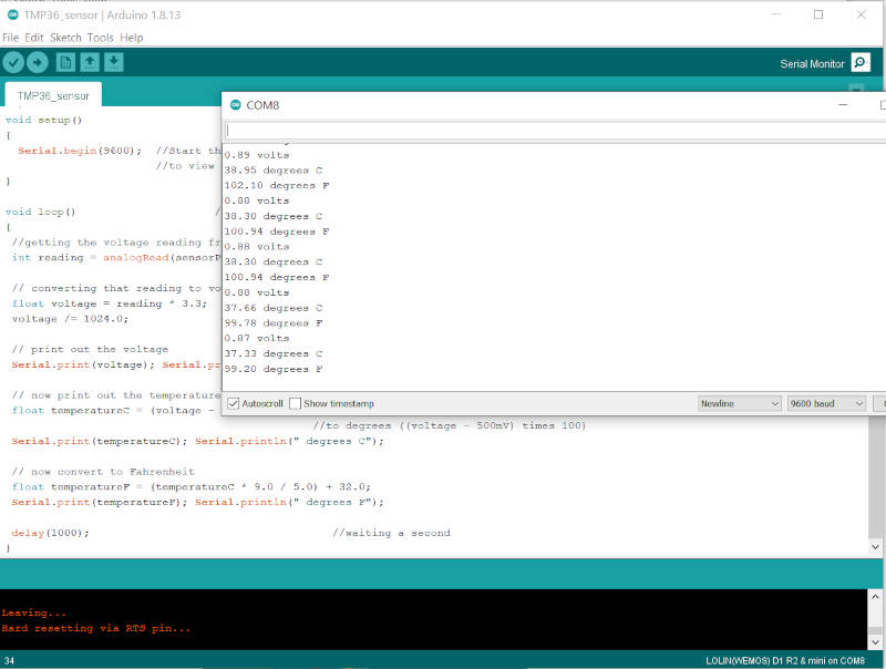
2. Temp sensor
https://learn.adafruit.com/tmp36-temperature-sensor
//TMP36 Pin Variables
int sensorPin = A0; //the analog pin the TMP36's Vout (sense) pin is connected to
                        //the resolution is 10 mV / degree centigrade with a
                        //500 mV offset to allow for negative temperatures

/*
 * setup() - this function runs once when you turn your Arduino on
 * We initialize the serial connection with the computer
 */
void setup()
{
  Serial.begin(9600);  //Start the serial connection with the computer
                       //to view the result open the serial monitor
}

void loop()                     // run over and over again
{
 //getting the voltage reading from the temperature sensor
 int reading = analogRead(sensorPin);

 // converting that reading to voltage, for 3.3v arduino use 3.3, else use 5
 float voltage = reading * 3.3;
 voltage /= 1024.0;

 // print out the voltage
 Serial.print(voltage); Serial.println(" volts");

 // now print out the temperature
 float temperatureC = (voltage - 0.5) * 100 ;  //converting from 10 mv per degree wit 500 mV offset
                                               //to degrees ((voltage - 500mV) times 100)
 Serial.print(temperatureC); Serial.println(" degrees C");

 // now convert to Fahrenheit
 float temperatureF = (temperatureC * 9.0 / 5.0) + 32.0;
 Serial.print(temperatureF); Serial.println(" degrees F");

 delay(1000);                                     //waiting a second
}
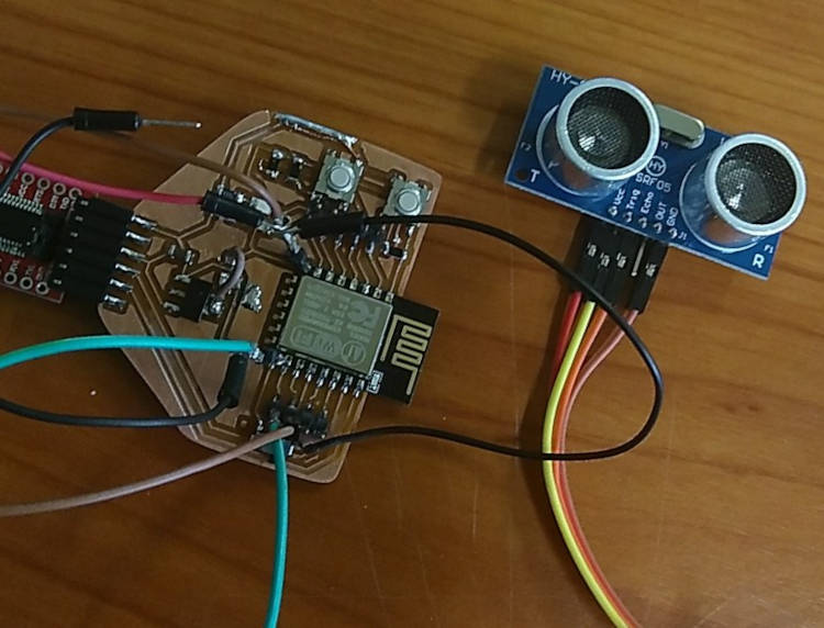
3. Sonar
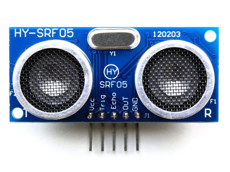
I connected the device with trigger pin on 4 and echo pin on 5. 3V as VCC and GND. It got no reading back. Then I realised I have to give this module 5V to work. So I connected it to the 5V pin on the FTDI adapter and got it working
const unsigned int TRIG_PIN=4;
const unsigned int ECHO_PIN=5;
const unsigned int BAUD_RATE=9600;

void setup() {
  pinMode(TRIG_PIN, OUTPUT);
  pinMode(ECHO_PIN, INPUT);
  Serial.begin(BAUD_RATE);
}

void loop() {
  digitalWrite(TRIG_PIN, LOW);
  delayMicroseconds(2);
  digitalWrite(TRIG_PIN, HIGH);
  delayMicroseconds(10);
  digitalWrite(TRIG_PIN, LOW);


 const unsigned long duration= pulseIn(ECHO_PIN, HIGH);
 int distance= duration/29/2;
 if(duration==0){
   Serial.println("Warning: no pulse from sensor");
   }
  else{
      Serial.print("distance to nearest object:");
      Serial.print(distance);
      Serial.println(" cm");
  }
 delay(100);
 }
- video Sonar
- measure Sonar pulse with osciloscope
- measure temp sensor with osciloscope
TODO!!!!
4. Redesigning the same board
I needed to redo the board to fix the problems I mentioned above. Make the GPIO0 switch between GND and 3V and also provide extra headers for power. This is the new design.
And after some milling adventures, I got a new soldered and working board. Now I can make use of it to catch up some assignments. I hope ;-)