♦ Networking and Communications ♦
This week is very interesting because in this week we are going to use communication protocol.We are going to make communication between two boards.In wednesday lecture Neil told about various communication protocol like I2C,SPI,CAN etc.On next day our instructor Suhas Sir gave brief lecture on what to do in this assignment,what is networking and how it works.
Please refer group assignment here:
Group Assignment:Send a message between two projects.
Individual Assignment:Design, build, and connect wired or wireless node(s) with network or bus addresses.
What is networking:
It is the interconnection of multiple devices, using multiple paths for the sending or receiving data or media.These data transfer through cable or wires or optic cables, or wireless media such as Wi-Fi.
A network protocol includes all the rules and conventions for communication between network devices,including ways devices can identify and make connections with each other.There are also formatting rules that specify how data is packaged into sent and received messages.
Communication:
Data communication refers to the transmission of the digital data between two or more computers .The physical connection between networked computing devices is established using either cable media or wireless media.The best-known computer network is the Internet.
The field of networking and communication includes the analysis, design, implementation,and use of local, wide-area, and mobile networks that link computers together.The Internet itself is a network that makes it feasible for nearly all computers in the world to communicate.
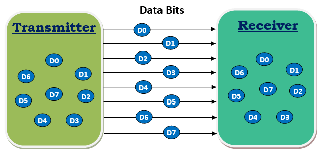
Parallel Communication:
In data transmission, parallel communication is a method of conveying multiple binary digits (bits) simultaneously. It contrasts with serial communication, which conveys only a single bit at a time;this distinction is one way of characterizing a communications link.
The basic difference between a parallel and a serial communication channel is the number of electrical conductors used at the physical layer to convey bits. Parallel communication implies more than one such conductor. For example, an 8-bit parallel channel will convey eight bits (or a byte) simultaneously, whereas a serial channel would convey those same bits sequentially, one at a time.If both channels operated at the same clock speed, the parallel channel would be eight times faster.
Serial Communication:
In serial communication, data is in the form of binary pulses.In other words, we can say Binary One represents a logic HIGH or 5 Volts, and zero represents a logic LOW or 0 Volts.Serial communication can take many forms depending on the type of transmission mode and data transfer.The transmission modes are classified as Simplex, Half Duplex, and Full Duplex.There will be a source (also known as a sender) and destination (also called a receiver) for each transmission mode.
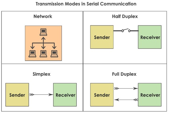
Simplex Method: The Simplex method is a one-way communication technique. Only one client (either the sender or receiver is active at a time).If a sender transmits, the receiver can only accept. Radio and Television transmission are the examples of simplex mode.
Half Duplex: In Half Duplex mode, both sender and receiver are active but not at a time,i.e. if a sender transmits, the receiver can accept but cannot send and vice versa. A good example is an internet. If a client (laptop) sends a request for a web page,the web server processes the application and sends back the information.
Full Duplex:The Full Duplex mode is widely used communication in the world. Here both sender and receiver can transmit and receive at the same time. An example is your smartphone.
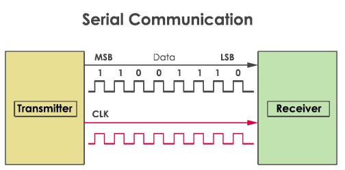
Serial data can be transferred in two ways-Asynchronous and Synchronous.
Synchronous serial interface : Synchronous Serial Interface (SSI) is a widely used serial interface standard for industrial applications between a master (e.g. controller) and a slave (e.g. sensor).SSI is based on RS-422 standards and has a high protocol efficiency in addition to its implementation over various hardware platforms, making it very popular among sensor manufacturers.
SSI is a synchronous, point to point, serial communication channel for digital data transmission.Synchronous data transmission is one in which the data is transmitted by synchronizing the transmission at the receiving and sending ends using a common clock signal. Since start and stop bits are not present, this allows better use of data transmission bandwidth for more message bits and makes the whole transmission process simpler and easier.The clock needs its own bandwidth and should be included when determining the total bandwidth required for communication between the two devices.
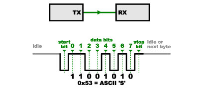
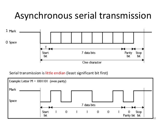
Asynchronous serial interface :Asynchronous serial communication is a form of serial communication in which the communicating endpoints' interfaces are not continuously synchronized by a common clock signal.Instead of a common synchronization signal, the data stream contains synchronization information in form of start and stop signals, before and after each unit of transmission, respectively.The start signal prepares the receiver for arrival of data and the stop signal resets its state to enable triggering of a new sequence.
I used I2C serial communication protocol for this week assignment.
I2C Protocol:
I2C combines the best features of SPI and UARTs. With I2C, you can connect multiple slaves to a single master (like SPI) and you can have multiple masters controlling single, or multiple slaves. This is really useful when you want to have more than one microcontroller logging data to a single memory card or displaying text to a single LCD.
Like UART communication, I2C only uses two wires to transmit data between devices:
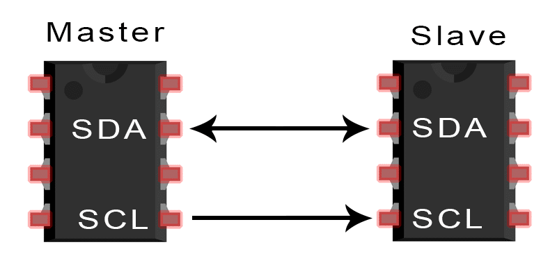
SDA (Serial Data) – The line for the master and slave to send and receive data.
SCL (Serial Clock) – The line that carries the clock signal.
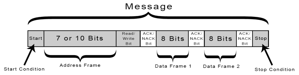
With I2C, data is transferred in messages. Messages are broken up into frames of data.Each message has an address frame that contains the binary address of the slave,and one or more data frames that contain the data being transmitted.The message also includes start and stop conditions, read/write bits, and ACK/NACK bits between each data frame:
Individual Assignment:
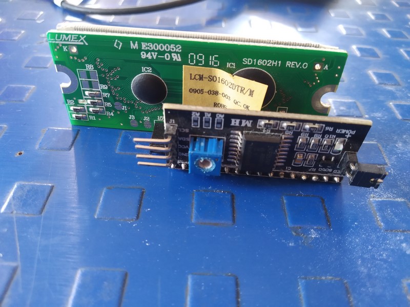
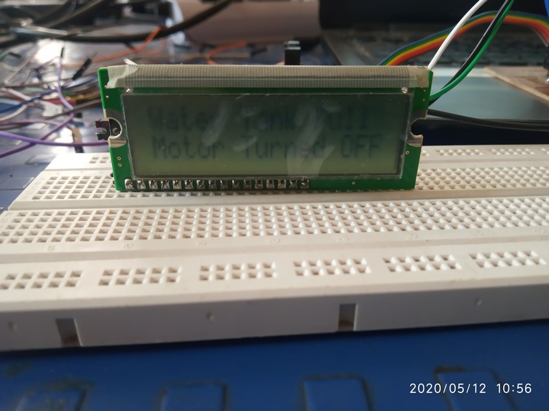
To check the I2C protocol I have used Vikram Sir board.He used 328p controller IC.On this board I have checked my input and output device.In that I connected ultrasonic sensor as input and LCD as output.I have connected I2C module to LCD.
|
|
I have connected I2C module to LCD.SDA and SCL pin of I2C connected to SDA and SCL pin of 328p.Ultrasonic sensor pin trigger and echo connected to PC3 and PC2.
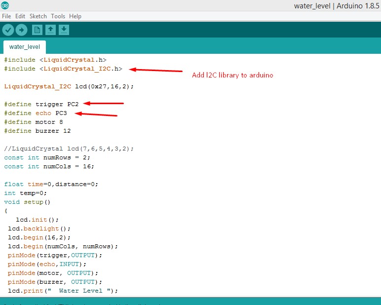
After connecting all connections ,I started uploading code to board.For I2C you need to add I2C library in arduino.I have defined echo and trigger pin in code.When I completed all changes I uploaded code to my board and it working as per code.
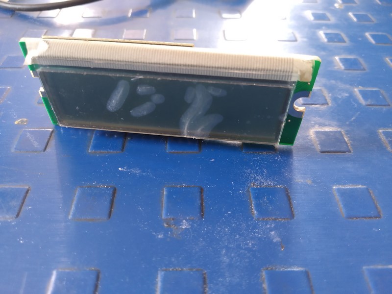
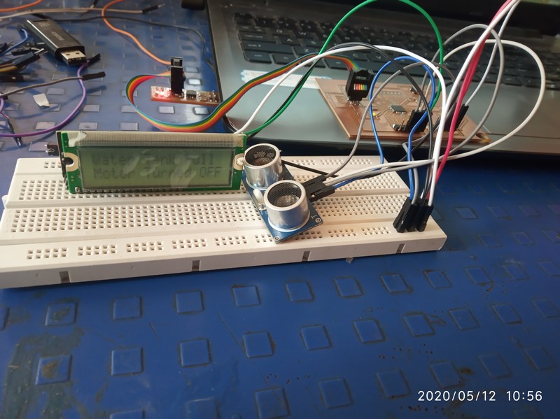
This is the output of my code and it working correctly.
|
|
|
RS232 Serial Bus:
In this Week I made two board i,e. master and slave (bridge and node)board.I followed Neil Board and re-route it.
1.Node - This board connect to the bridge board to receive the signal or for communicate.
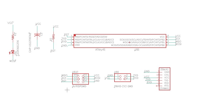
I made schematic diagram of node and bridge board in eagle.
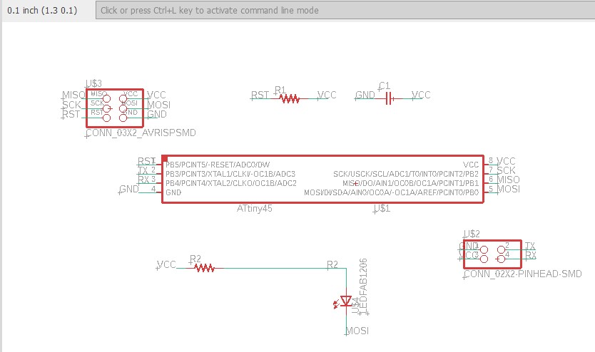
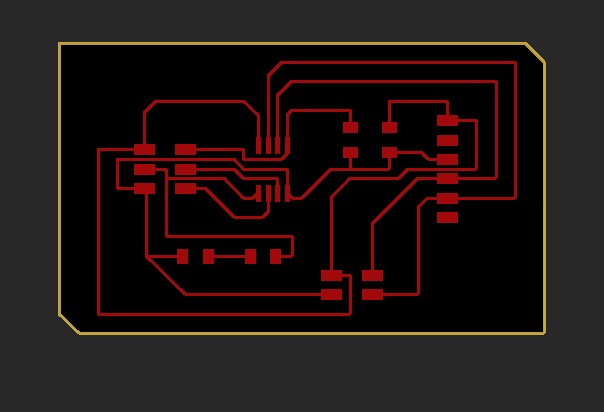
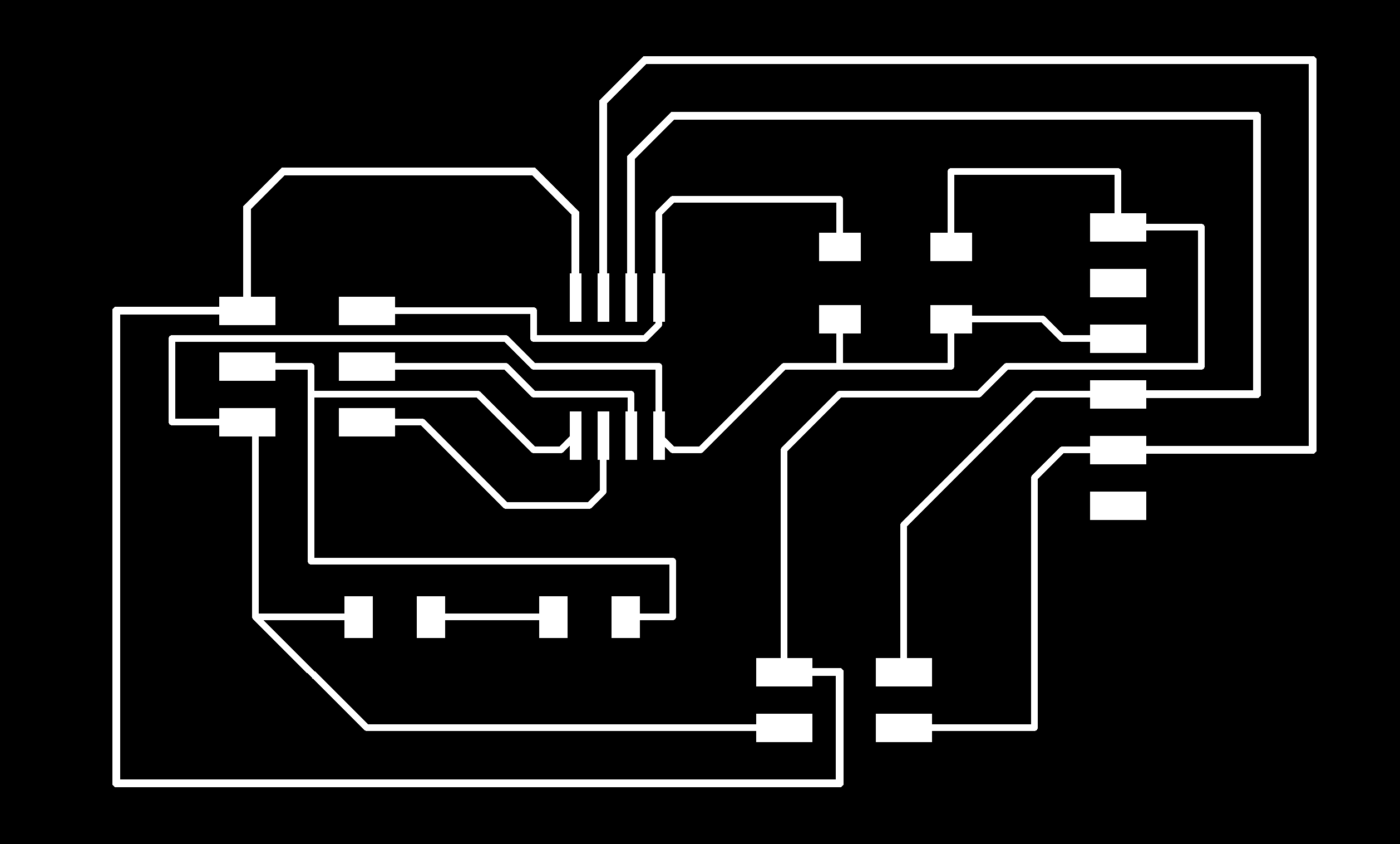
After schematic I routed the board .
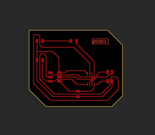
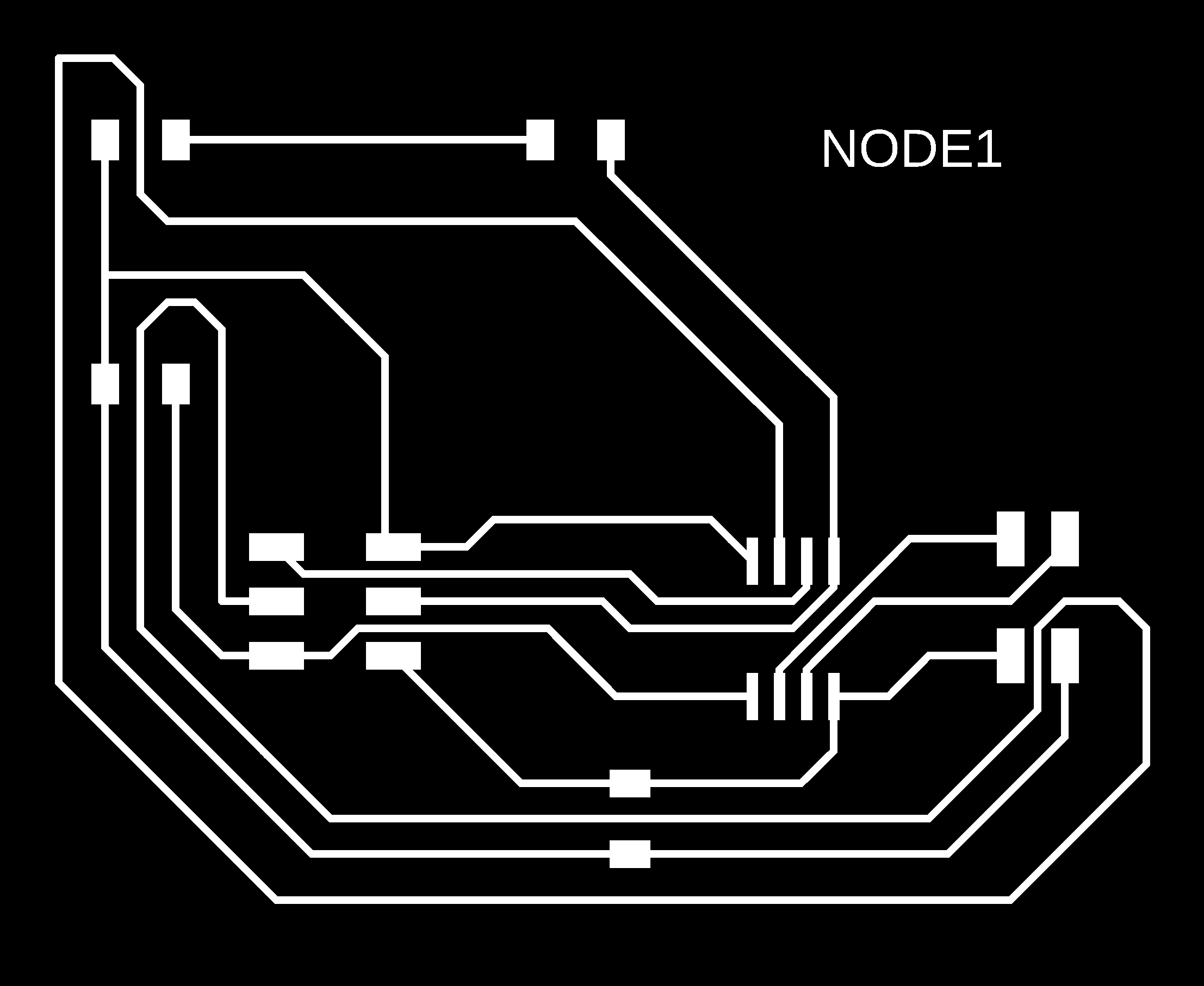
|

|
2.Bridge - This board communicates with the serial port and other board with the help of FTDI cable.
Schematic diagram of bridge board
After schematic routing board look like this
|

|
After designing I converted all png file into RML using Mods and milled the board using SRM-20.
Then I collected all component from fab inventory as Neil given in his board.I soldered my board.
Programming:
After soldering and testing of the board then I going to program it and its uploaded in board as well.
In my bridge board I defined Node Address is 0.The code for Bridge serial communication with node.
Same code but need to change the node ID in the code.In my Node board .I defined Node Address is 1 for first node board and defined another node address is 2 for second board.
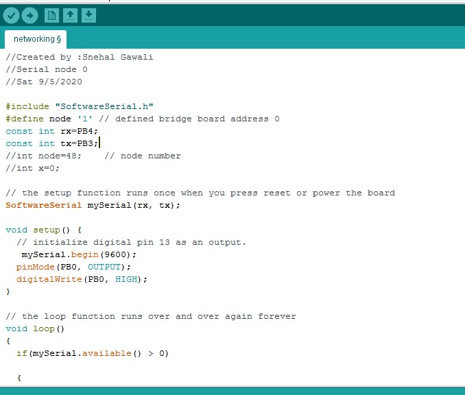
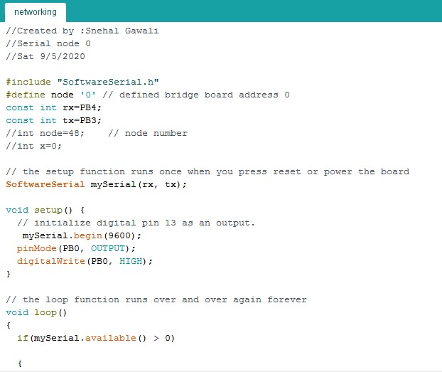
Here is the code for node and bridge,just change the node Id ,for bridge its 0 and for node its 1 and 2.
                          //Created by :Snehal Gawali
//Serial node 0
//Sat 9/5/2020

#include "SoftwareSerial.h"
#define node '1' // defined bridge board address 0
const int rx=PB4;
const int tx=PB3;
//int node=48;    // node number
//int x=0;

// the setup function runs once when you press reset or power the board
SoftwareSerial mySerial(rx, tx);

void setup() {
  // initialize digital pin 13 as an output.
   mySerial.begin(9600);
  pinMode(PB0, OUTPUT);
  digitalWrite(PB0, HIGH);
}

// the loop function runs over and over again forever
void loop()
{
  if(mySerial.available() > 0)

  {
    //mySerial.print("here");
    int x=mySerial.read();
    delay(1000);
   // mySerial.print(x);

  if (x==node)
    {
    digitalWrite(PB0, LOW);   // turn the LED on (HIGH is the voltage level)
    delay(500);
    digitalWrite(PB0, HIGH);
    delay(500);

        }
  }
}
Then I arranged the board in serialy.I used 3x3 Pin header with Ribben cable to make a communication Bus.I connected RX and TX from each board using ribben cable. Then I checked continuity.I connected RX,TX,GND,VCC of bridge to node board.First code uploaded separately in each board.We dont have FTDI cable ,so I used arduino to make serial communication.I connected RX,TX,VCC,GND of bridge to arduino.
Arduino used as FTDI
I know that the ATtiny45 has no hardware for serial communication. That's why I am using a FTDI -USB cable and the SoftwareSerial library.First you should remove the micro controller from the board you don't want to program or else you will be programing both micro controllers. Or connect reset pin to GND pin .For using arduino to make serial communication I have connected arduino RX,TX,VCC,GND to bridge board.As for bridge board and arduino using same RX and TX pin.
To resolve this problem we can define another RX and TX pin for bridge board.Because of this we will get different pins for arduino and for bridge to node board connection.In this case I have used PB3 and PB4 as TX and RX.We can define it as PB2 or PB1.
In serial monitor, When I pressed 0 and clicked Enter then Blinking LED of bridge board beacause I defined 0 Node ID for bridge board.Same think in Node board.but in Node board I pressed 1 and 2 Node ID.
Here is the output video
