♦ Output Devices♦
This week is about output devices.On wednesday Neil took lecture on output devices ,in lecture he told about various devices which act as output devices.What are the functions of output devices ,how it show the output.These all things covered by Neil.On next day our instructor Suhas Sir and Arundhati Ma'am gave brief about assignment .They told about various output devices,how to make board and how to test it.
Please refer group assignment here:
Group Assignment:Measure the power consumption of an output device.
Individual Assignment:Add an output device to a microcontroller board you've designed, and program it to do something.
Individual Assignment:
An output device is any piece of computer hardware equipment which converts information into human-readable form.It can be text, graphics, tactile, audio, and video.
For my final project I need ultrasonic sensor as input devices and LCD ,buzzer as output device.So I decided to work on my final project board.I am using ESP32 controller for my project.I started working on design.
For output device I will be using LCD display to show the water level.First I started study of LCD i.e how it works,what are another type of displays.
LCD(Liquid Crystal Display)
A liquid-crystal display (LCD) is a flat-panel display or other electronically modulated optical device that uses the light-modulating properties of liquid crystals combined with polarizers.Liquid crystals do not emit light directly,instead using a backlight or reflector to produce images in color or monochrome.
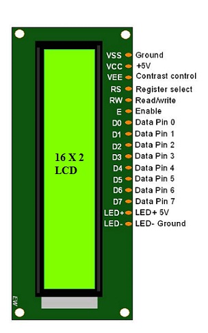
16x2 LCD contain 16 pin,which include GND,VCC,data pins,enable,read/write pins.
LCD
The operating voltage of this LCD is 4.7V-5.3V. It includes two rows where each row can produce 16-characters. The utilization of current is 1mA with no backlight. Every character can be built with a 5×8 pixel box. The alphanumeric LCDs alphabets & numbers
OLED:
OLED (Organic Light Emitting Diodes) is a flat light emitting technology, made by placing a series of organic thin films between two conductors. When electrical current is applied, a bright light is emitted.OLEDs are emissive displays that do not require a backlight and so are thinner and more efficient than LCD displays (which do require a white backlight).
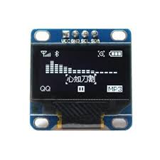
OLED
Type: Graphic
Structure: COG+PCB
Size: 0.96"
128 x 64 Dot Matrix
Built-in controller SSD1306BZ
3V/5V Power supply
1/64 duty
Interface: I2C
4 Pin OLED Display
Display Color: White / Yellow / Blue
OLED VS LCD
An OLED display have the following advantages over an LCD display:
Improved image quality - better contrast, higher brightness, fuller viewing angle, a wider color range and much faster refresh rates.
Lower power consumption.
Simpler design that enables ultra-thin, flexible, foldable and transparent displays.
Better durability - OLEDs are very durable and can operate in a broader temperature range.
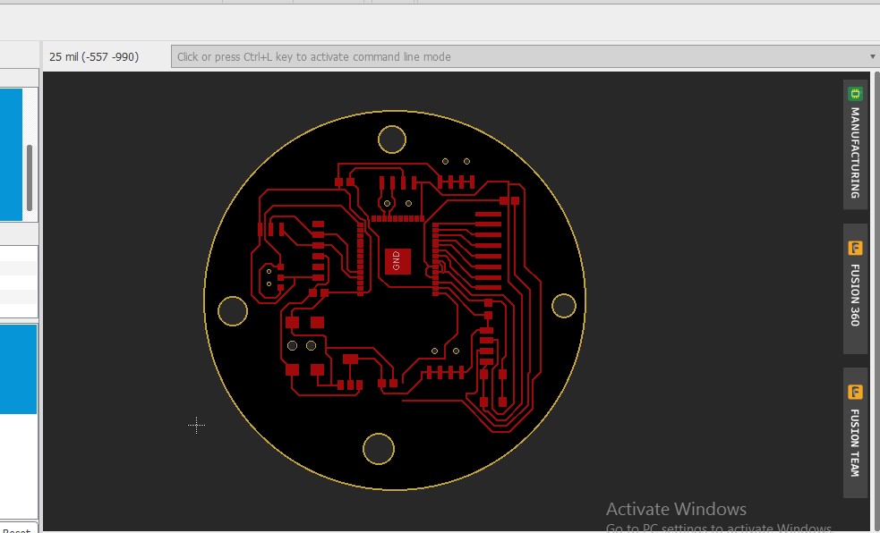
DESIGN:
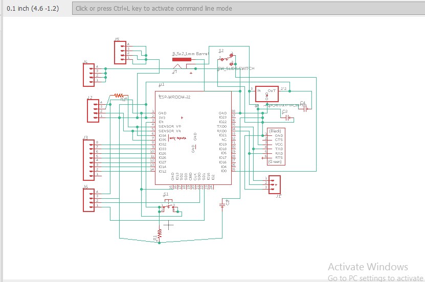
I designed my board in EAGLE.In eagle ESP32 library is not there.So I downloaded library from github and added to eagle.
|
|
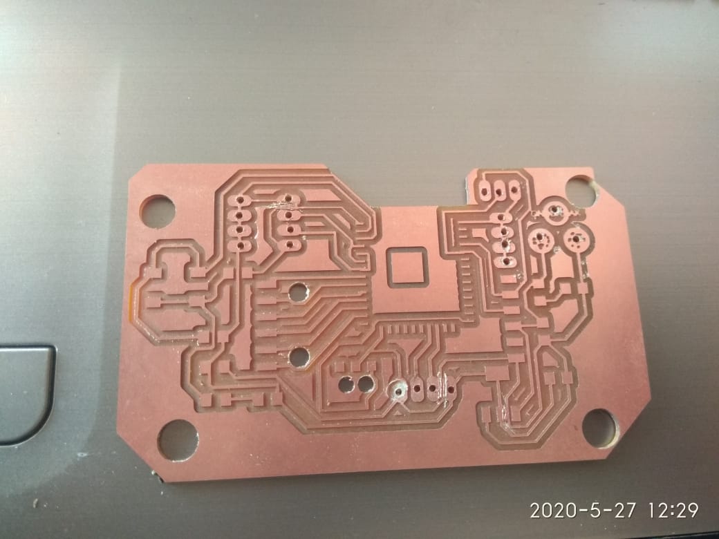
After completion of design ,I milled my board using SRM-20 .But there is some bed levelling issue thats why board is not milled properly.
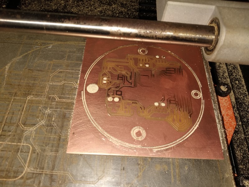
Milling
Error:
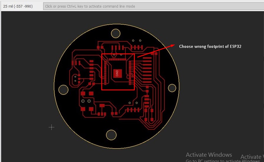
I choose wrong ESP32 footprint.Because of this pad size of that esp32 is large and thats why all pads get short.So I again downloaded new ESP32 wroom footprint and added to eagle.Be careful when you are selecting footprint.
Error
Because of this again I drawn new schematic using new footprint.
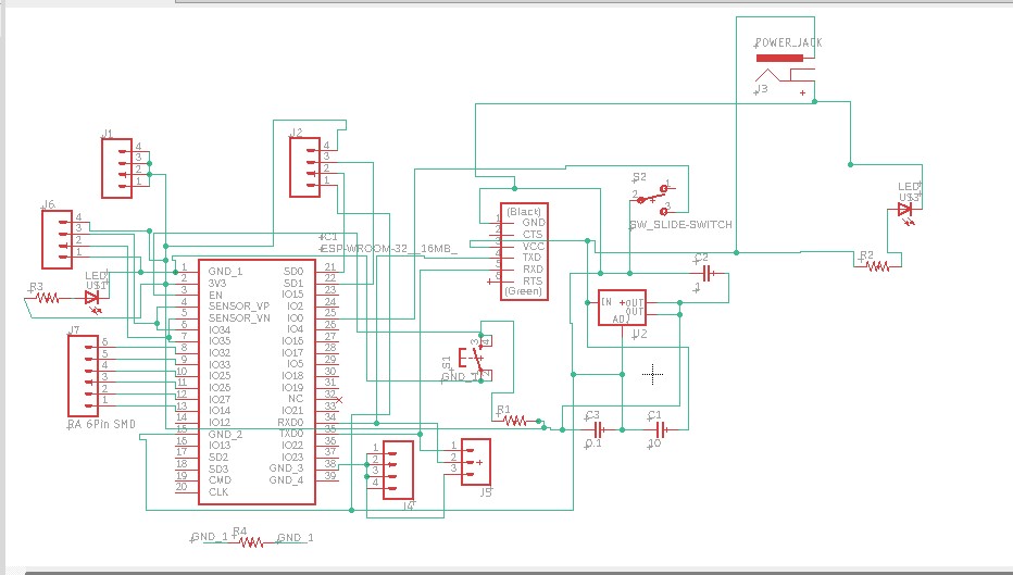
Schematic
Now I am routing the board.After routing I will mill my board.
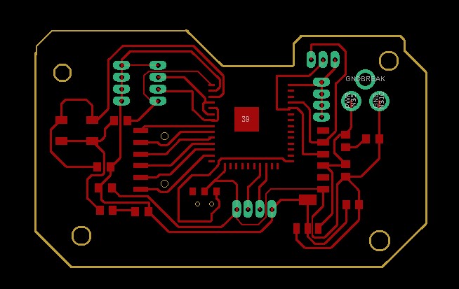
board
After completion of design I started milling of board.

This is final milled pcb.
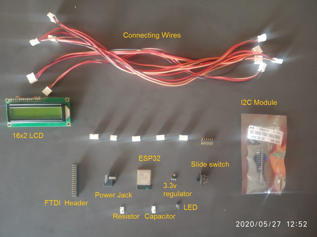
This is all required components for pcb.
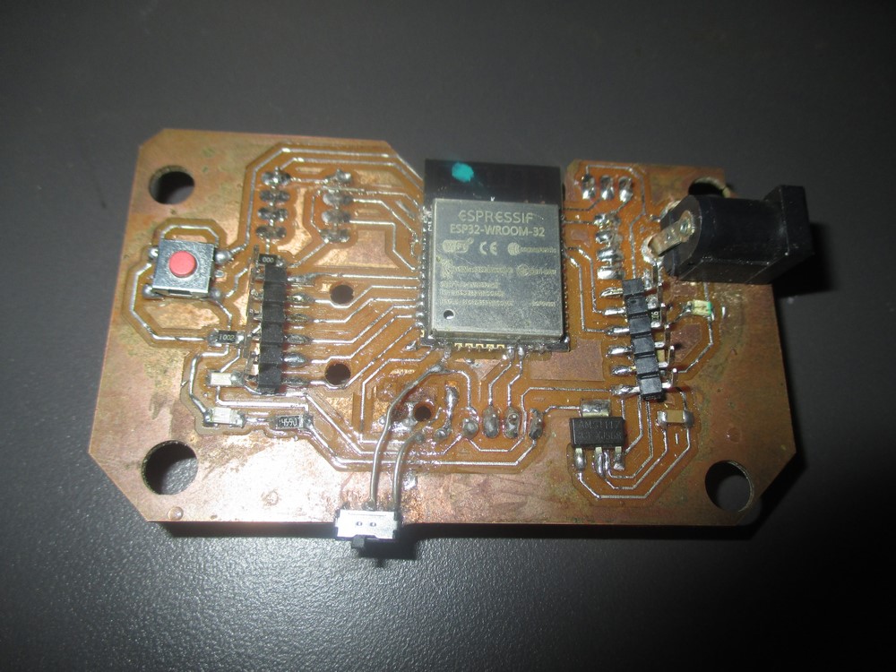
I have soldered all components and final board looks like this
In our FAB inventory we have LCM-S01602DTR/M 16 X 2 LCD display.The 16 X 2 LCM-S01602DTR/M pin out is shown below.
Pin1 VSS :This is a GND pin of display, used to connect the GND terminal of the microcontroller unit.
Pin2 VDD: This is the voltage supply pin of the display, used to connect the supply pin of the power source.
Pin3 V0: This pin regulates the difference of the display, used to connect a changeable POT that can supply 0 to 5V.
Pin4 RS: This pin toggles among command or data register, used to connect a microcontroller unit pin and obtains either 0 or 1(0 = data mode, and 1 = command mode).
Pin5 R/W : This pin toggles the display among the read or writes operation, and it is connected to a microcontroller unit pin to get either 0 or 1 (0 = Write Operation, and 1 = Read Operation).
Pin6 E :This pin should be held high to execute Read/Write process, and it is connected to the microcontroller unit & constantly held high.
Pin7-14 DB0-DB7: These pins are used to send data to the display. These pins are connected in two-wire modes like 4-wire mode and 8-wire mode. In 4-wire mode, only four pins are connected to the microcontroller unit like 0 to 3, whereas in 8-wire mode, 8-pins are connected to microcontroller unit like 0 to 7.
Pin15 NC:
Pin16 NC:
Pin 15 and 16 are not connected pins.Don't connect anything to that pin.Just connect pin 1 to 14 to backpack.
Connecting I2C to LCD and Microcontroller:
First connect pin 1 to 14 of I2C to LCD .Don't connect pin 15 & 16.After that connect I2C pin VCC,VDD,SDA,SCL to microcontroller pin of VCC ,VDD and SDA(21) ,SCL(22) pin.
Install the LCD display library to Arduino:
After interfacing microcontroller to I2C 16x2 LCD module next step is to download liquid crystal I2C library for arduino.Follow the next steps:
Step 1.Firstdownload Liquid crystal I2C library
Step 2.Go to Arduino IDE
Step 3.Go to sketch -> Include Library -> Add.zip file
Step 4.Check the install library
Programming:
As I used I2C module along with 16 X 2 LCD display first you need to find out address of I2C with 16 x 2 module.For that I used I2C scanner program to determine the address and also it is connected or not.Please refer the below code ,it will find device address and display on arduino serial monitor.
#include <Wire.h>


void setup()
{
  Wire.begin();

  Serial.begin(9600);
  Serial.println("\nI2C Scanner");
}


void loop()
{
  byte error, address;
  int nDevices;

  Serial.println("Scanning...");

  nDevices = 0;
  for(address = 1; address < 127; address++ )
  {
    // The i2c_scanner uses the return value of
    // the Write.endTransmisstion to see if
    // a device did acknowledge to the address.
    Wire.beginTransmission(address);
    error = Wire.endTransmission();

    if (error == 0)
    {
      Serial.print("I2C device found at address 0x");
      if (address<16)
        Serial.print("0");
      Serial.print(address,HEX);
      Serial.println("  !");

      nDevices++;
    }
    else if (error==4)
    {
      Serial.print("Unknow error at address 0x");
      if (address<16)
        Serial.print("0");
      Serial.println(address,HEX);
    }
  }
  if (nDevices == 0)
    Serial.println("No I2C devices found\n");
  else
    Serial.println("done\n");

  delay(5000);           // wait 5 seconds for next scan
}
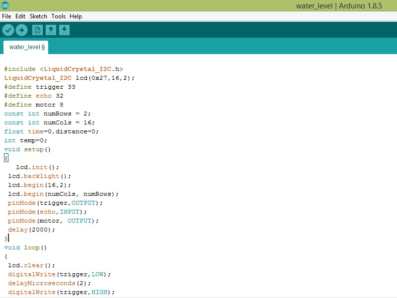
I uploaded this code in my board.I got the address value on serial monitor.The address of my LCD is 0x27.I have used this address in my next code.
This is code for I2C display.In this code I have added I2C library and I have declared sensor pins i.e echo and trigger which I have mentioned in pcb design.Display connected to SDA,SCL,VCC and GND pin.
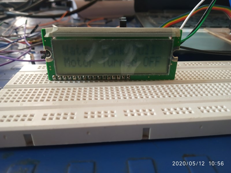
I have declared echo and trigger pin.This code show the output of water level according to condition.I have added condition like if distance goes beyond some limit it will display that water tank is full and vice versa.
This is final output of my board which is showing output on display.