Electronics design
Week 9- Documentation
Assignments:
- Group assignment: Probe an input device's analog levels and digital signals
- Individual assignment: Measure something: add a sensor to a microcontroller board that you have designed and read it
Photoresistor:
Because of the Covid-19 situtation I've been sent home in quarentine and have not been fully enabled to do this weeks assingment on my own boards so I have been using Arduino Uno for the assignment.
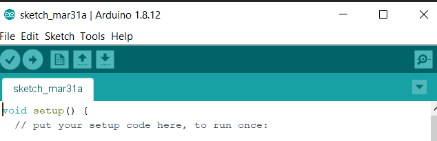
- I started out by opening up the Arduino software that I downloaded in the previous week.
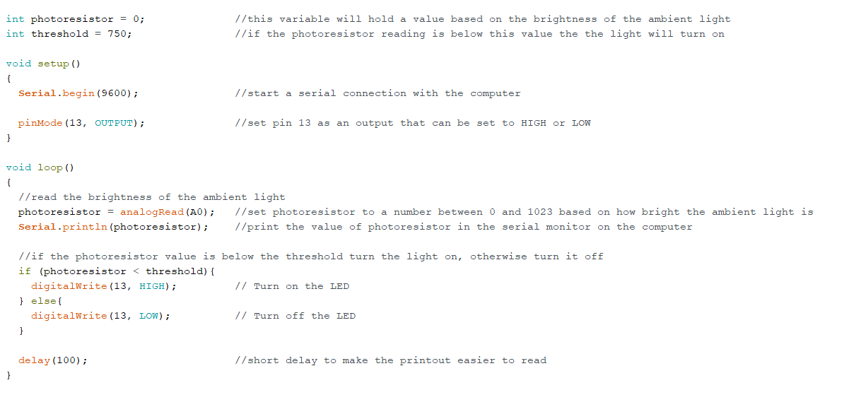
- After opening the Arduino it was time to start coding.
- When I had finished coding for the photometric sensor I connected the Arduino Uno and and started out by verifying the code by clicking the verify button, this button lets you know if your code is ok. Then I clicked upload and then the code gets uploaded to the Arduino Uno.
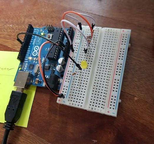
- After uploading the code to the Arduino I started connecting all the parts and sensor to the Arduino through breadboard.
Materials
- Arduino Uno x1
- Breadboard x1
- Photoresistor sensor x1
- Wires x6
- 10k ohm Resistor x1
- 330 ohm Resistor x1
- LED x1
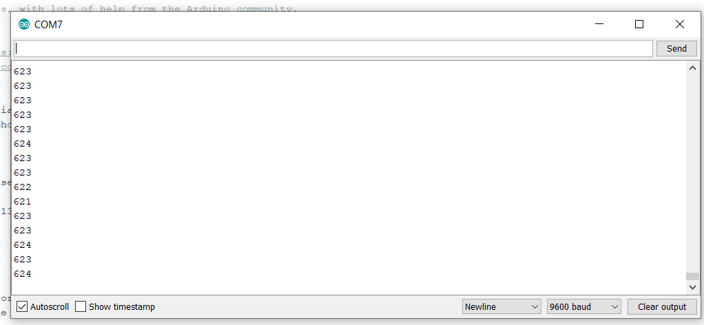
- After connecting all of the pats correctly the Arduino started to measure light automatically and then I clicked the serial monitor button and there I could see the light measurements. I tested the sensor by using a flashlight to increase the light and then I could see the numbers on the screen rising to over 1000 witch meanes that the sensor works properly. And when I turned off the lights the number got lower.
Problems:
I had no major problmes during this build, the only problmes I had was that I forgot a couple of semicoms (;) and the the Arduino software told me that those lines that had it missing that something was wrong with them and all I needed to do was to fix them and click verify again to make sure that everything was ok.
Temperature sensor:
- I started out by opening up the Arduino software that I downloaded in the previous week.
- After opening the Arduino it was time to start coding.
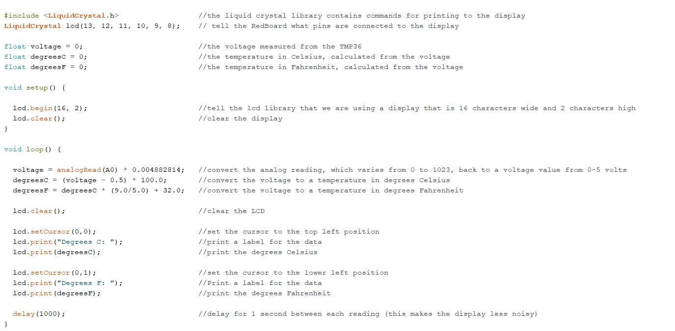
- When I had finished coding for the temperature sensor I connected the Arduino Uno and and started out by verifying the code by clicking the verify button, this button lets you know if your code is ok. Then I clicked upload and then the code gets uploaded to the Arduino Uno.
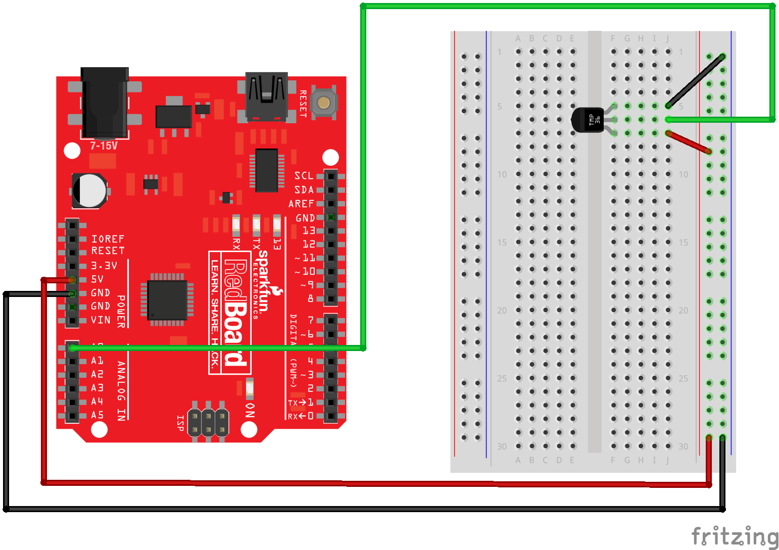
- After uploading the code to the Arduino I started connecting all the parts and sensor to the Arduino through breadboard.
Materials
- Arduino Uno x1
- Breadboard x1
- Photoresistor sensor x1
- Wires x6
- 10k ohm Resistor x1
- 330 ohm Resistor x1
- LED x1
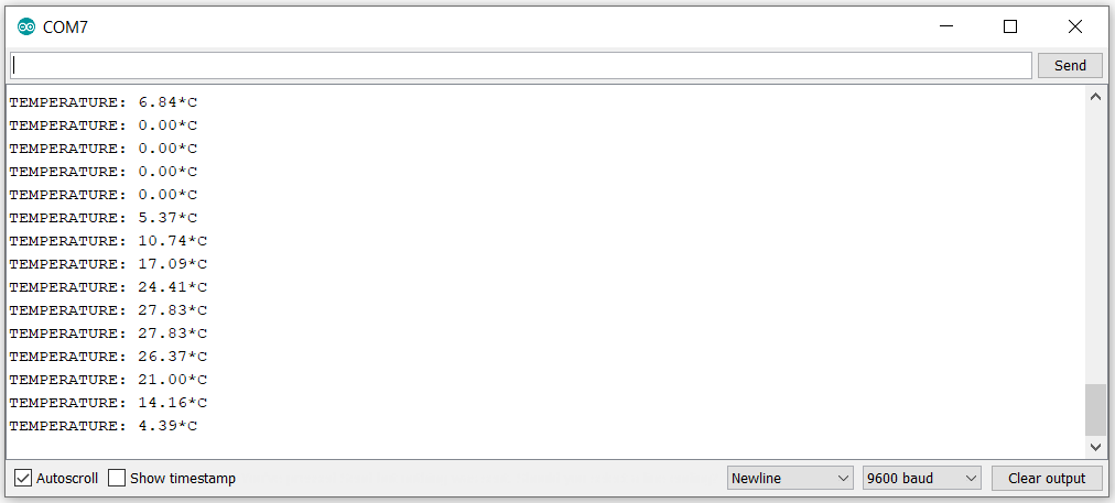
- After connecting all of the pats correctly the Arduino started to measure temperature automatically and then I clicked the serial monitor button and there I could see the temperature measurements and the numbers did not make sens. I tested the sensor by touching it and hoped the numers would rise but it did'nt. I was not able to fix it but I thing I fried the sensor because I started out by connecting it wron and I could feel that the sensor went really hot.
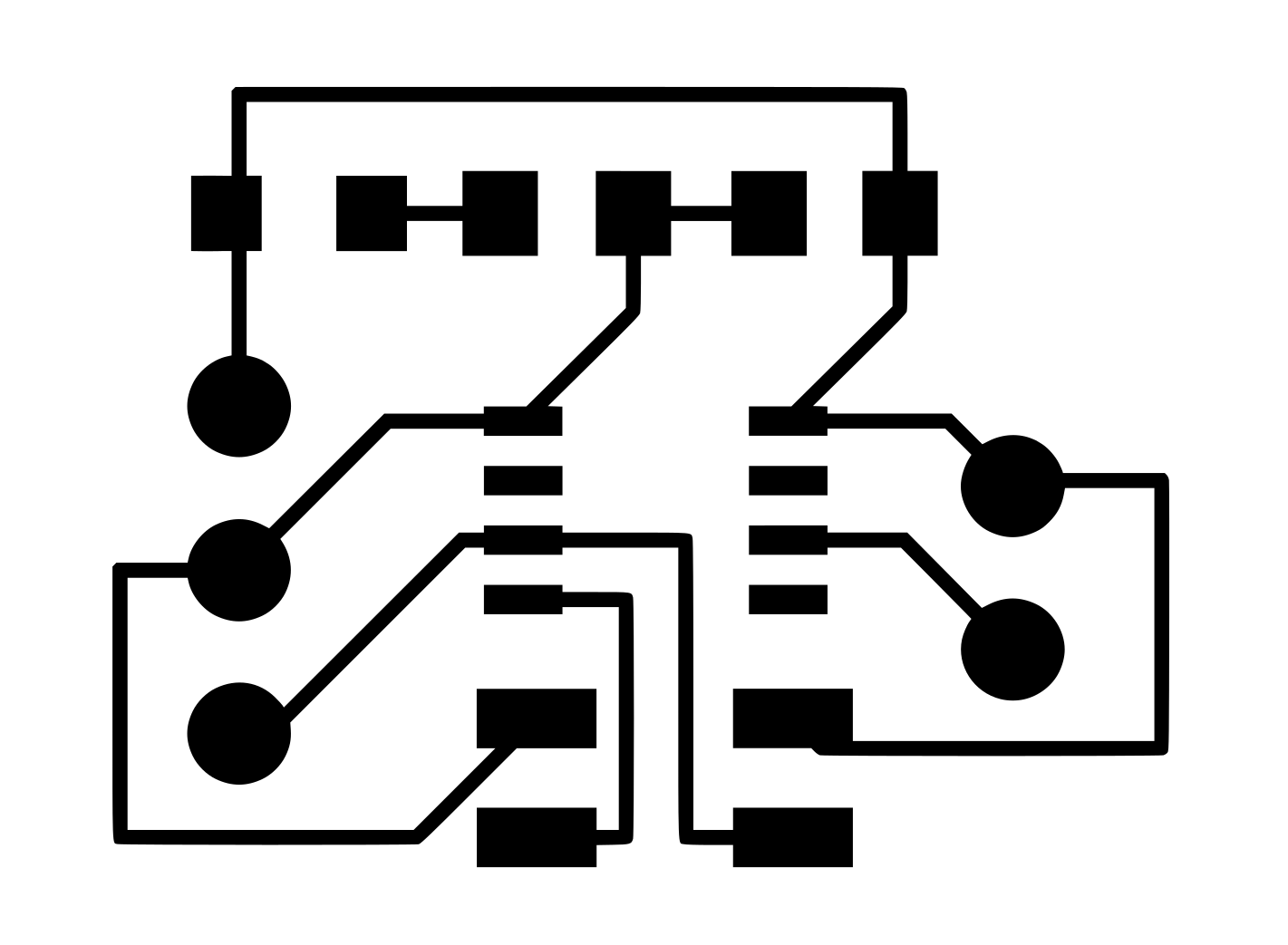
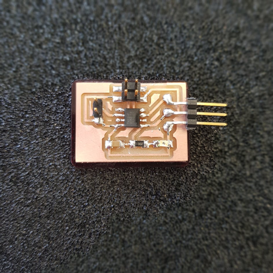
Phototransisror:
After I got out of quarentine and started working on my final project I soon started working on the phototransistor board. The phototransistor board or the light board as I call it uses attiny412 as a microcontroller. The board sends data from the phototransistor to the motherboard where the data get's sent to the LCD screen. features:I started out by looking at the design of Niel's phototransistor board and drawing that in Eagle but I changed it a little bit. I used Attiny412 instead of Attiny45. After designing the board I milled it out and sodered the componenets on it and then I made a small plexi glass platform that indicated who designed and made it(it was me) and what kind of sensor it is(phototransistor sensor). After all that I coded it with an epoxy to keep it safe from moisture and water.
Tutorials I used:
- Sparkfun: Experiment 6: Reading a Photoresistor
- Eli the computer guy: Photoresistor Light Sensor with Arduino
- MakeCrate: How does a photoresistor work
- Sparkfun: Experiment 7: Reading a Temperature Sensor
Files:
Software I used:
- Arduino: Coding software.