Electronics design
Week 6- Documentation
Assignments:
- group assignment: Use the test equipment in your lab to observe the operation of a microcontroller circuit board
- individual assignment: redraw an echo hello-world board, add (at least) a button and LED (with current-limiting resistor) check the design rules, make it, and test it extra credit: simulate its operation
Designing the board:
Before this assignment I had never worked with Eagle and it was a fun challenge working with it. The reason behind me choosing Eagle instead of KiCAD is that I really like Autodesk and see myself in the future working a lot with Autodesk software. Here is a great tutorial about Eagle workflow.
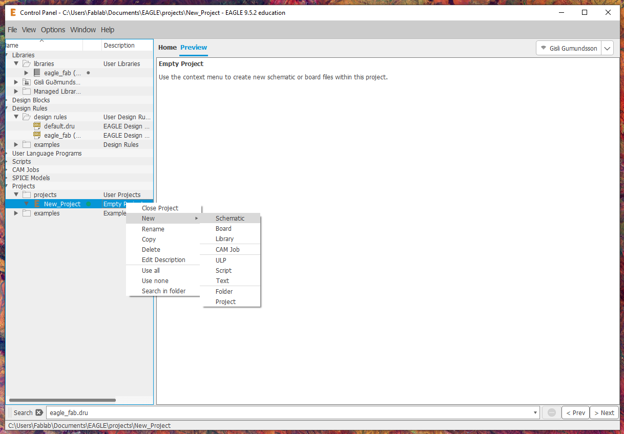
- I started out by downloading the file for libraries and design rules (Link to files).
To download the file you go to the file that you want to download and there in the top right corner you will fing the download button. After you have downloaded the files you find them on your computer and drag them into Eagle. You drag the .dru file to the design rules folder and the .lbr file to libraries and when you have done that you have imported the librarie and design rules into Eagle. - After moving the libraries and design rules into Eagle I started to design the board. I found a board that served the right purpose that I wanted (Hello board thathad a LED and a button). I started out by opening up a new schematic.
- I started out by imported the right parts into the Schematic by clicking "add part" and finding the right part in the librarie that I had imported to Eagle.
The parts:
- ATTiny44
- Resonator 20MHZ
- C 1uF
- 2x R 10k ohm
- Button
- FTDI
- LED
- 6 pin connector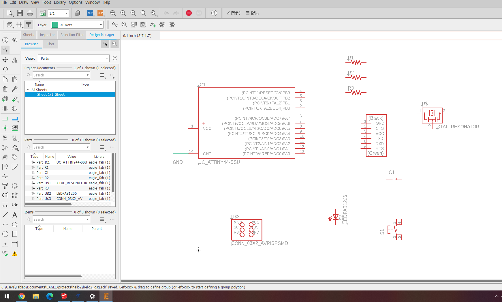
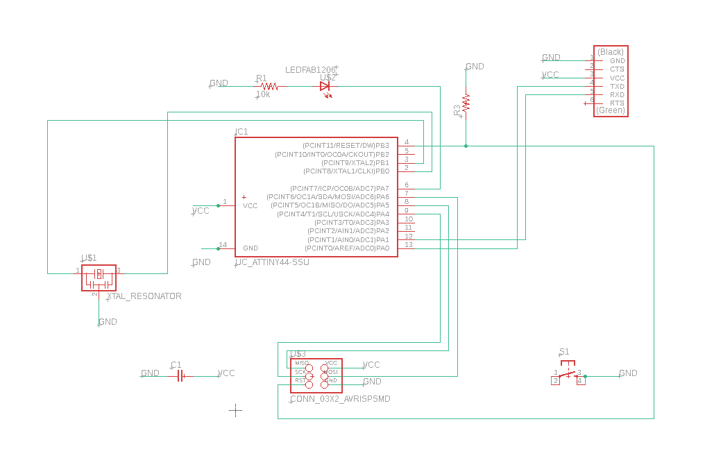
- After adding all the parts to the schematic I started to connect all the parts together like they where supposed to. To connect parts together you click "net" and the net tool lets you drag a line to connect parts.
- When you have connected all the parts correctly together you go to file and go to the board.
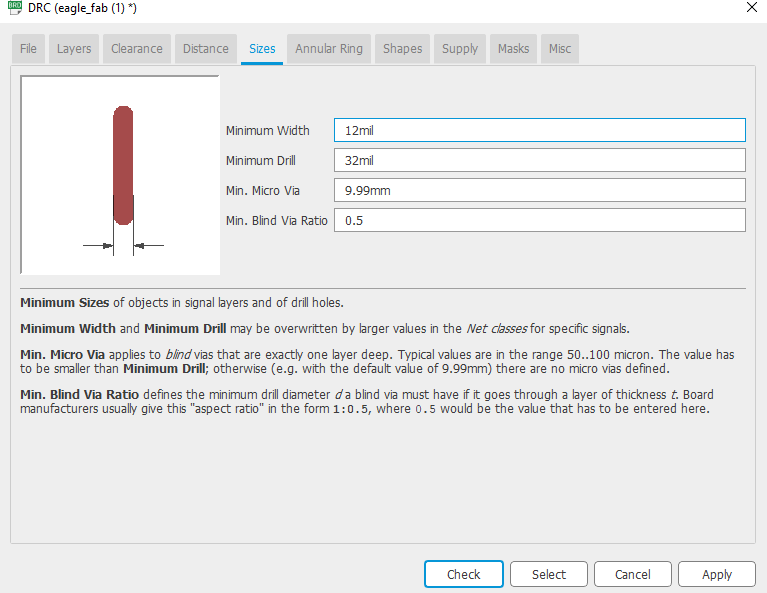
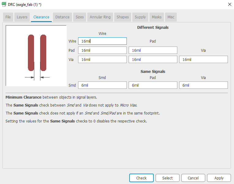
- In the board you can change the design rules by clicking DRC in the bottom left corner. Here are the design rules that I used:
- In the board you make the circuits and choose how you want your board to be set up. To move the parts around you smiply click on the cross on each part and move it around. To make routes you use the route airwire and drag lines where you want to have the routes. It can be pain in the ass to find the right place for everything. >
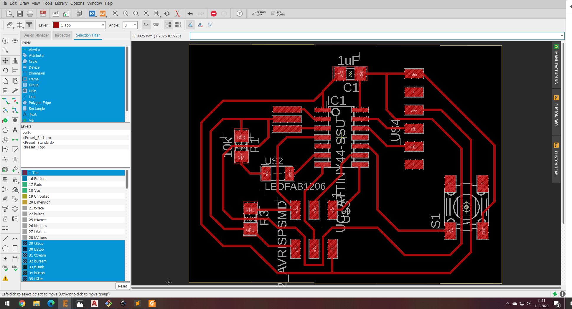
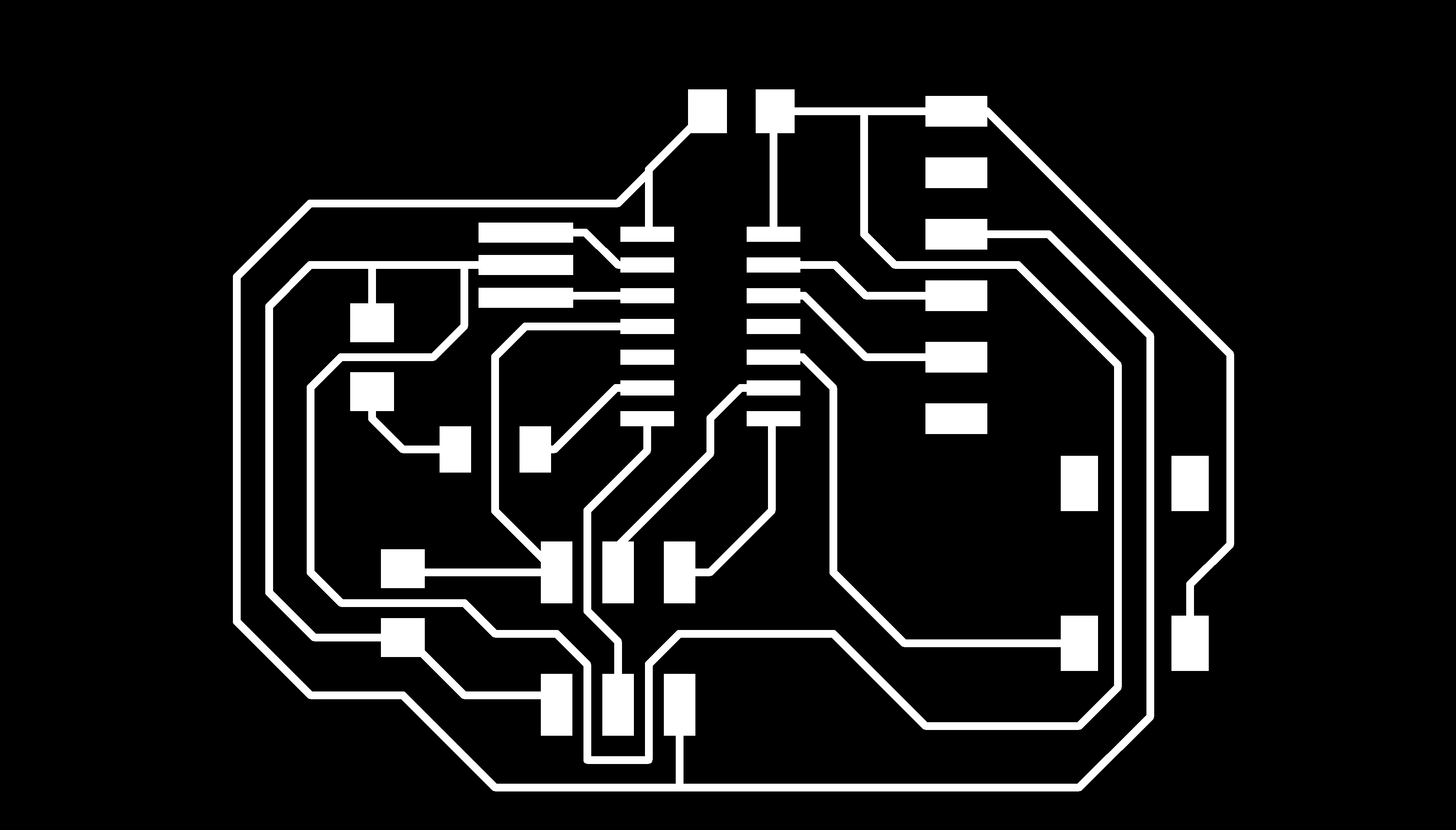
- When you are happy with the placement of everything you export the file as image. Make sure when you are exporting is to turn off all of the layers that you don't want by going to layers and turning them off. Also make sure to make it monochrome by clicking the monochrome button when exporting.
- Next up is to import the image into Gimp and cut out all the part that you dont want. When you have saved the image after cropping you are going to use the same image and now you want to remove all the things that you want(all of the circuits) and make an image for the outlines and make sure to click "save as" not "save" because you need both images. The first images is for the circuits and the other is for the outlines.
- After this it's time to make the board.

Couple of comments:
The diagram shows that I'm using Attiny44, button, capasator, resonator, resistor, FTDI and a 3x3 pin connector. When designing the board I used Eagle to designing it and after I had designed it I found out that there is a feature that is called autorouter and it connects the board automatically and I did not use that feature and I'm eager to learn more about that feature in future builds. In the design process my thinking process was not right so I did not consider the effect of bouncing at all nor any solutions of hardware for de-bounching.
All of the parts are using both GND and VCC. The FTDI is also connected to the RX(recive) and the TX(transfer) witch transfer and recieve data through those pins. It's important that the led has a resistor in front of the LED and if not the LED will burn over and get destroyed. The reson why I'm using the 10k resistor for the LED is because the board is a mixture of Niel's boards and he uses 10k resistor infront of the LED and in the data sheet for the LED it said that it needs a 10k resistor. I connected the GND side of the led to the button and when the button is clicked it sends a message to pin 10 of the attiny44 and depending on how I programm the attiny44 how the LED reacts to that, in my case it starts to blink so the button is active low. The setup of the button is a pull up resistor and I did not think of using current limiting resistor for the button because when I was making the board I did not know anything about them and if I would have read the datasheet better I might have used one. In designing this board I was not reading a lot of datasheet's for the build but the datasheet's that I read where about the Attiny44 and the LED(LED green clear 1206 SMD) and those datasheets helped me deciding on what resistor I should use with the LED and about the pinout and where all of the pins should be connected to the microcontroller.
Making the board:
- Fabmodules.org (computer)
- I started out by finding .png for the circuit and outlines and started by inserting the images into Fabmodules.org
- In fabmodules I clicked the "output format" and made the image into "Roland mill(.rml)". I selected "process" and selected "PCB traces (1/64)" wich means that the tool that is used is 1/64". For the circuit I used 1/64" and for the outlines I used 1/32".
- After that selected the settings for the milling. The settings that I changed:
- Machine: MDX-20
- x0(mm): 0
- x0(mm): 0
- Cut depth: 0.2 - After chancing the setting I clicked "calculate" and then Fabmodules calculated the tool path.
- After Fabmodules had calculated the tool path I clicked "save"
- After saving the circuit I reapeated the process with the outlines but changed the tool to 1/32" and the cut dept to 1.7mm to cut through the bord.
- I got myself a copper board and placed a double sided tape on the back side and plced the board on the milling machine. I placed the board so it's straight to minimise the waste of material.
- Turned on the milling machine
- The next thing that I did was to find myself a 1/64" drill bit and inserted it into the milling machine. I placed it high because later when I zero the z I will lower it. It is also important to not tighten the screew too hard because it's fragile.
- I opened Roland MDX 20 conrtol panel and the software asked me "Witch COM port is Roland MDX20 connected to? (a,b...): a=COM1, b=COM3, c=COM5" and I selectef "c" and clicked "ok".
- In the software there are buttons above and big yellow space below that when you click somewhere in yhe yellow space and the milling machine moves to that spot. I started by clicking around until I had placed the drill bit over the bottom left corner of the brass plate to waste as little materila as possible.
- After finding the place where I wanted to have my X and Y axis I clicked "Set XY" and that makes the place that the drill bit is placed over the 0 axis.
- To zero the Z axis I moved the drill bit as low as possible but left about one cm left so that the milling machine would be able to drill. When I had lower the drill I losen up the drill bit but made sure to not drop the drill bit (if it drops it brakes) and lowered it carefully down to the plate and then thighten the screw again. Note: if you 0 your Z axis somewhere else than on your XY the machine will not lift the drill when it's moves to the XY and it will scrape the board and possibly destroy the drill. So that does not happen you need to lift the drill bit useing the commands on the computer by clicking "Z-up"untill your are happy with the hight. If you move the Z up by using the buttons on the machine you will lose the Z axis and then need to make another Z axis.
- The next thing to do is to load the file so I clicked "load file" and selected the circuit file because you want to start by making the circuit, if you start by cutting the outlines the plate has only the tape to hold it and will most likely move around and then the cuts will not be accurate. After you load your file the machine starts to cut automatically. This cut will take about 15 minutes.
- After the milling machine had finished cutting the circuit the next thing to do is to cut the outlines. To do that you repeat the same process all you need to change is the drill bit, to cut the outlines you use 1/32" instead the 1/64". You need to change the drill bit in both the machine and on Fab modules (where you generate the file). Also what you need to change is the cut dept and you also do that on Fab modules and you change that to 1.7mm. On the outlines you want to cut throug the board.
- After removing the boards form the milling machine it's important to wash the boards with soap and water. It's enough to wash it with soap and water. This is important because this process cleans the board and removes a lot of roughness that may be when the board is fresh out of the milling machine.
- Next step is soldering and I like to start by going through the blueprints of what I'm making and in this case it's Fab ISP44. In this pice there are 14 compoanents you need to solder to your board.
- How to solder:
- Mount the component
Begin by inserting the leads of the LED into the holes of the circuit board. Flip the board over and bend the leads outward at a 45′ angle. This will help the component make a better connection with the copper pad and prevent it from falling out while soldering. - Heat The JointTurn your soldering iron on and if it has an adjustable heat control, set it to 400’C. At this point, touch the tip of the iron to the copper pad and the resistor lead at the same time. You need to hold the soldering iron in place for 3-4 seconds in order to heat the pad and the lead.
- Apply Solder To JointContinue holding the soldering iron on the copper pad and the lead and touch your solder to the joint. IMPORTANT – Don’t touch the solder directly to the tip of the iron. You want the joint to be hot enough to melt the solder when it’s touched. If the joint is too cold, it will form a bad connection.
- Snip The Leads Remove the soldering iron and let the solder cool down naturally. Don’t blow on the solder as this will cause a bad joint. Once cool, you can snip the extra wire from leads.
A proper solder joint is smooth, shiny and looks like a volcano or cone shape. You want just enough solder to cover the entire joint but not too much so it becomes a ball or spills to a nearby lead or joint.
- Mount the component
- How to desolder:
- Step 1 – Place a piece of the desoldering braid on top of the joint/solder you want removed.
- Step 2 – Heat your soldering iron and touch the tip to the top of the braid. This will heat the solder below which will then be absorbed into the desoldering braid. You can now remove the braid to see the solder has been extracted and removed. Be careful touching the braid when you are heating it because it will get hot.
- Optional – If you have a lot of solder you want removed, you may want to use a device called a solder sucker. This is a handheld mechanical vacuum that sucks up hot solder with a press of a button.
To use, press the plunger down at the end of the solder sucker. Heat the joint with your soldering iron and place the tip of the solder sucker over the hot solder. Press the release button to suck up the liquid solder. In order to empty the solder sucker, press down on the plunger.
- When you have finished soldering all the components to your board it's time for programming.


On the milling machine (Roland MDX 20)
Roland MDX 20 conrtol panel


Manual


Problems:
There was a couple of proplems with Roland MDX 20 conrtol panel and Fab modules.
- When I had 0 the Z axis and did not have the drill on the 0 for the XY and started to mill the machine would move to the XY 0 without raising the Z so the drill scraped the board, scraching the board and possibly destroying the drill bit. To make that problem go away I tried raising the Z up by using the buttons on the machine but then I had lost the Z axis and neded to make another 0 for the Z. I finally realize that I neded to press "Z up" on the program so would not loose the Z.
- I also had a problem with the quality of my cuts and that problem was fixed by chainging the drill bit for a neew one.
- The problem with Fab modules was that it was not doing it's job correctly and made an error when making the code. I had tried a couple of times and was constantly making new codes and somehow it newer finished cuttint the last line in the outline and one time it just went straight to the middle and destroyed the circuit. I fixed that problem by using an old file form the first cut when the cut wasn't good quality.
Files:
- Eagle Schematic
- Eagle Board
- Image circuit board
- Image outlines
- Circuit milling file
- Outlines milling file
Software I used:
- Eagle: is included with Fusion 360. Unify mechanical CAD and electronics into a single platform.
- Gimp: Free & Open Source Image Editor.