Week 6 - 3D Scanning and Printing
This week is dedicated to 3D Scanning and Printing. One objective of this week is to learn about the limitations of 3D printing. A 3D object can either be made by additive or subtractive processes. Obviously in subtractive machining there is a cutting tool removing material while additive machining is deposing it.
FAB ACADEMY 2020 source
20200226 Scanning Printing from Academany on Vimeo.
My Assignment
This week the group assignment was about finding the design rules of our 3D Printer, the Original Prusa I3 MK3S. To do that we decided to print an Open-Source 3D Printer torture test available on GitHub. We also tested the capabilities of the Low Force Stereolithography 3D Printer: Form 3.
The individual assignment consisted in two things: first, design and 3D print an object that could not be made subtractively and second, 3D scan an object.
Design and 3D Printing
For this part of the assignment I decided to print scaled elements of a scenography: a Japanese Torii and branch screens. This is the scenography of an original creation: "Le Thé de Kinoko", produced by La Compagnie de L'hydre. I found the design and printing of the screens very challenging. Indeed trees are seldom the same and they are difficult to design and print. Another challenge I wanted to take up was to design an assembly that would be printed all at once and that would not require any mounting except maybe some cleaning. For this challenge, I chose to design and print a Geneva mechanism.
Software
Here is the list of the software used to design and print the objects:
Machine
All the pieces have been printed with the Original Prusa I3 MK3S and a nozzle of 0.4mm.
Work Flow
The scenography
To design the Torii I used SolidWorks then I exported the file with the .STL format.
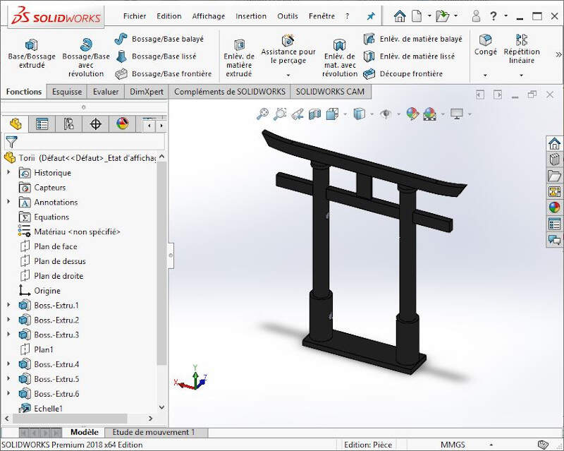
3D Design of the Torii with SolidWorks
In PrusaSlicer I imported the .STL file and I used the default setting "0.1mm DETAIL MK3". I also used the "Rotate" command to place the Torii in the most adequate position for printing.
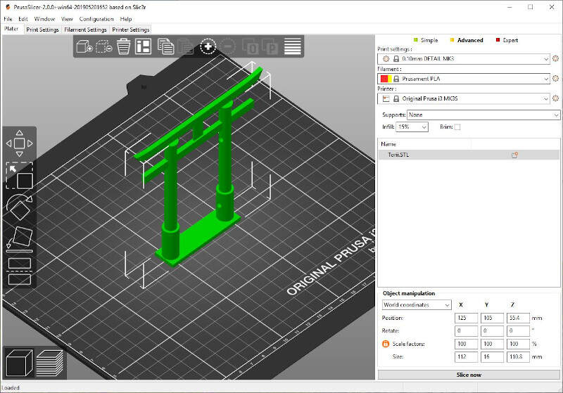
Importing .STL file of the Torii in PrusaSlicer
As the Torii is a tall object with a thin base I modified the default parameters of the skirt to increase the adhesion of the Torii to the printer plate. In the "Advanced mode" of PrusaSlicer in "Layers and perimeters" I changed the "Skirt height" to 3 layers and the "Brim Width" to 10 mm.
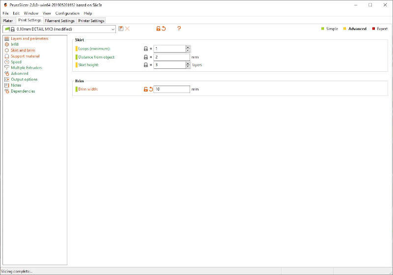
Setting skirt and brim parameters in PrusaSlicer
I also auto-generated a support material to increase the quality of the printing beneath the arch of the Torii.
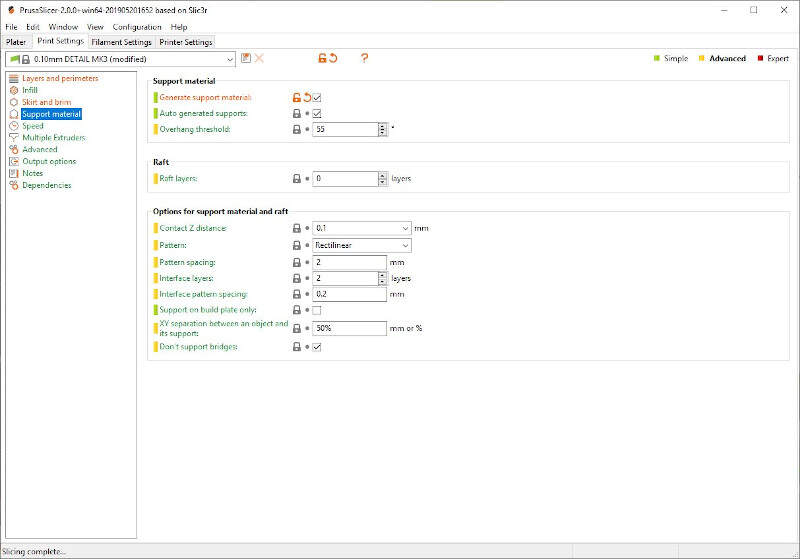
Setting support material parameters in PrusaSlicer
Then I pressed the button "Slice now" and the following preview was rendered by PrusaSlicer. It displayed each layers of 0.1mm and gave some information about the printing such as the printing time, the use of filament and even a cost estimation.
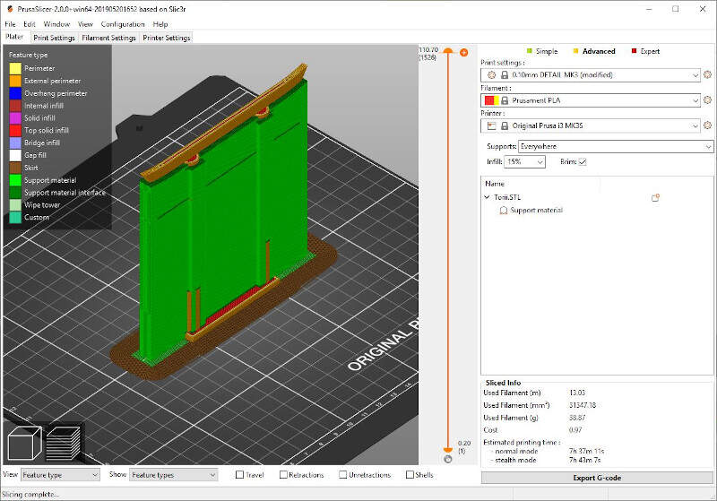
"Slice now" and "Export G-CODE" in PrusaSlicer
After removing the support enforcers, the brim and the skirt here is the result of the printing.
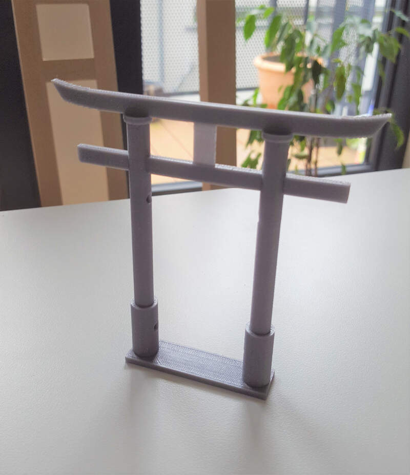
3D printing of the Torii after removing the support enforcers
For the scenography I also needed two branch screens. I did them with Blender. The challenging design procedure I used to create trees is explained here, in the week dedicated to 3D design. Afterwards, to prepare the file for printing, I used a Blender Add-on: 3D Print. It helped me to correct the mistakes in the mesh and to generate a volume to print. Finally I exported the file with a .STL format.
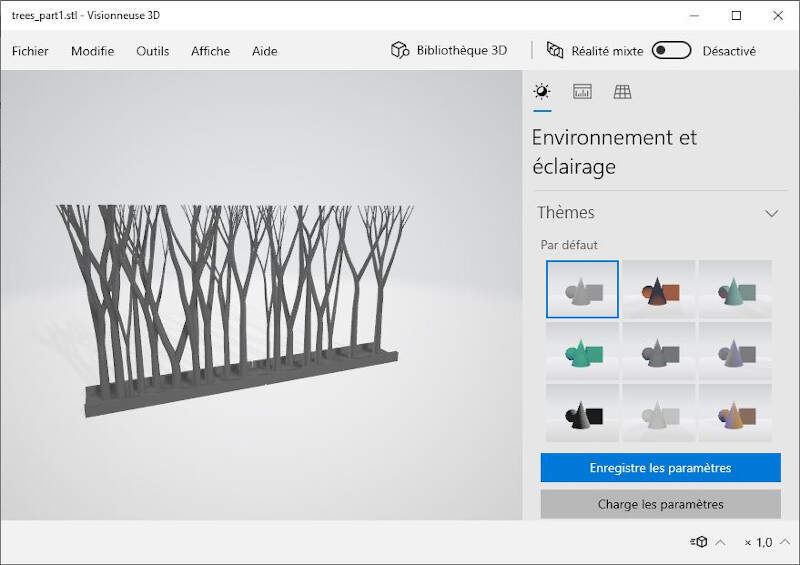
3D Design of the branch screen with Blender
In PrusaSlicer I imported the .STL file and I scaled the branch screen with the "Scale" tool. I didn't use any support enforcer because the tree branches were quite small at the top and an enforcer might be difficult to remove without breaking them.
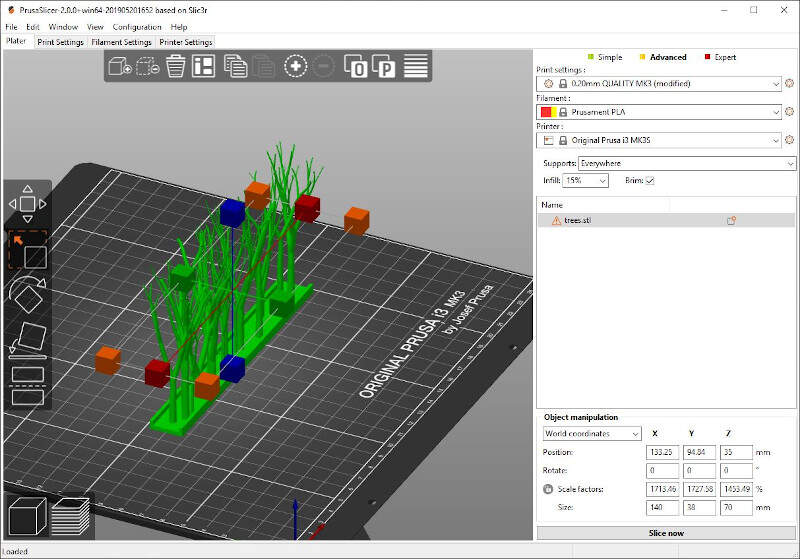
Scaling of the branch screen in PrusaSlicer
After 3 hours 36 minutes this was the result of the printing. I was quite satisfied by it but there was still a little bit a cleaning to do to remove the brim and also the "spider-webs" between the branches. Removing the brim was easy but removing the "spider-webs" was something else. To remove the "spider-webs" I used different technics: I first tried to cut them then I used acetone to smooth the shape. Then I tried to directly remove them with acetone but the test was not really convincing to smooth the hair roots. The acetone also degraded the surface color but I didn't care too much about that as I wanted to paint the scenography elements later.
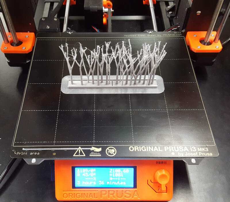
3D printing of the branch screen
To paint the PLA objects I applied two layers of black acrylic paint on the Torii and I used red, yellow, black and white acrylic paints to give some color shades to the branches. With these layers of paint the surface state is much smoother.
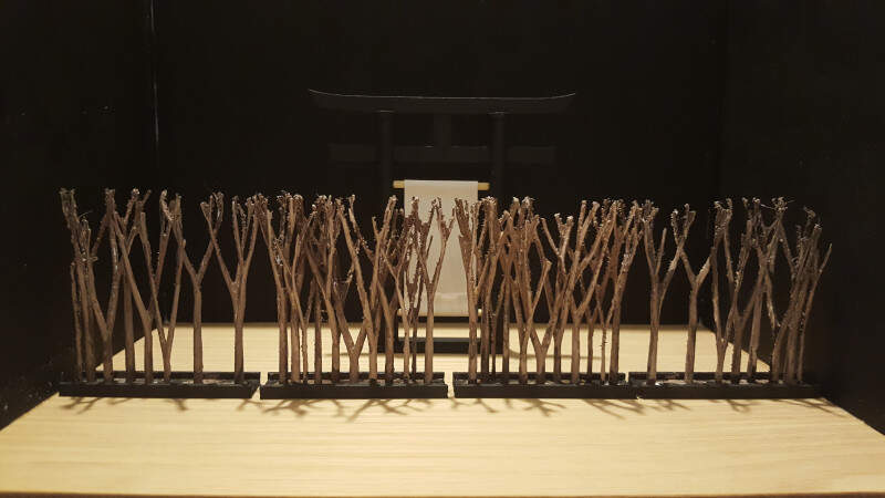
Final result of the scaled scenography with the Torii and the branch screens being painted with acrylic
Here is the final result of the scaled scenography.
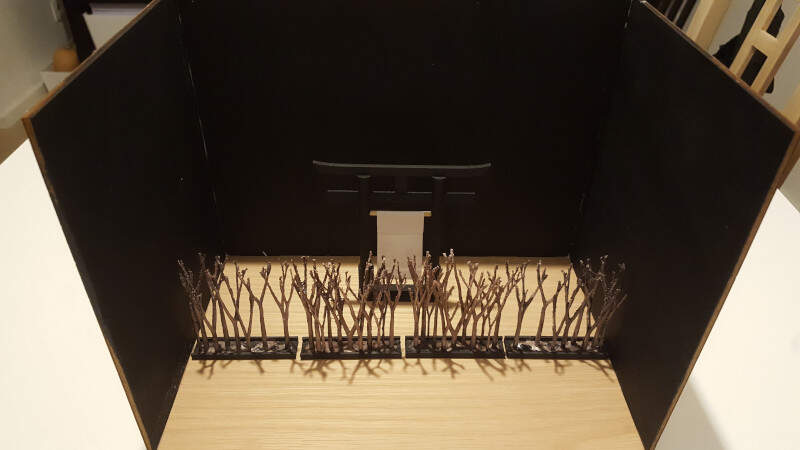
Another view of the scaled scenography
The Geneva mechanism
Another challenge I wanted to take up with 3D printing was to print an assembly. The assembly I chose to design and print is called a Geneva mechanism. It is one of the most commonly used devices for producing intermittent rotary motion, characterized by alternate periods of motion and rest.
To design it I used SolidWorks. I first made three separate parts and then I assembled them with distance constrains in an assembly file. After that, I exported the file as an .STL file that I imported in PrusaSlicer.
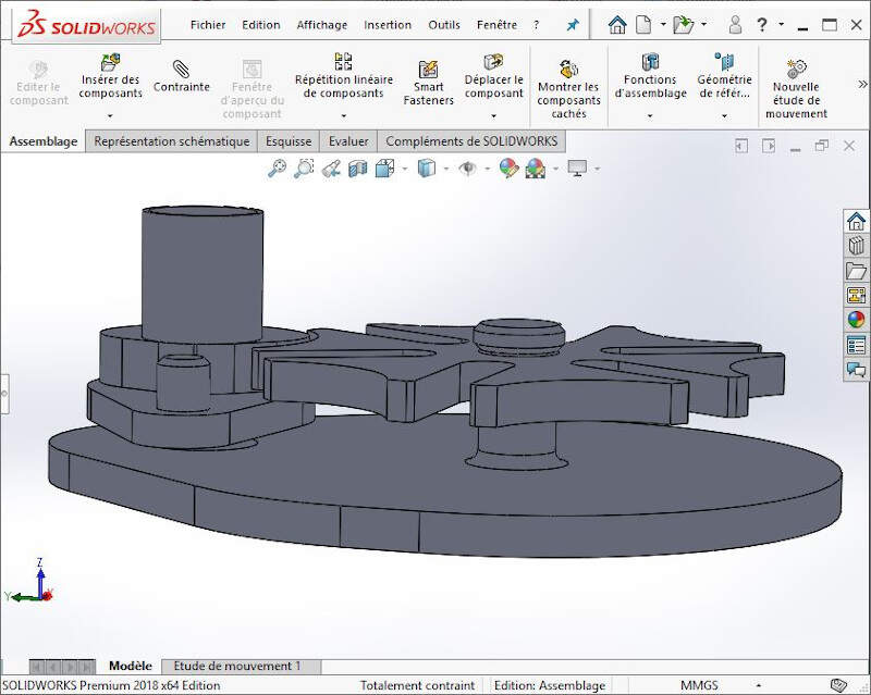
Assembly with SolidWorks
In PrusaSlicer I placed support enforcers by myself by right-clicking on the object and selecting "Add Support Enforcers". The reason for not generating them automatically is due to the fact the I didn't want to have enforcers to close from the joints because they might be too difficult to remove and they also might block the joint.
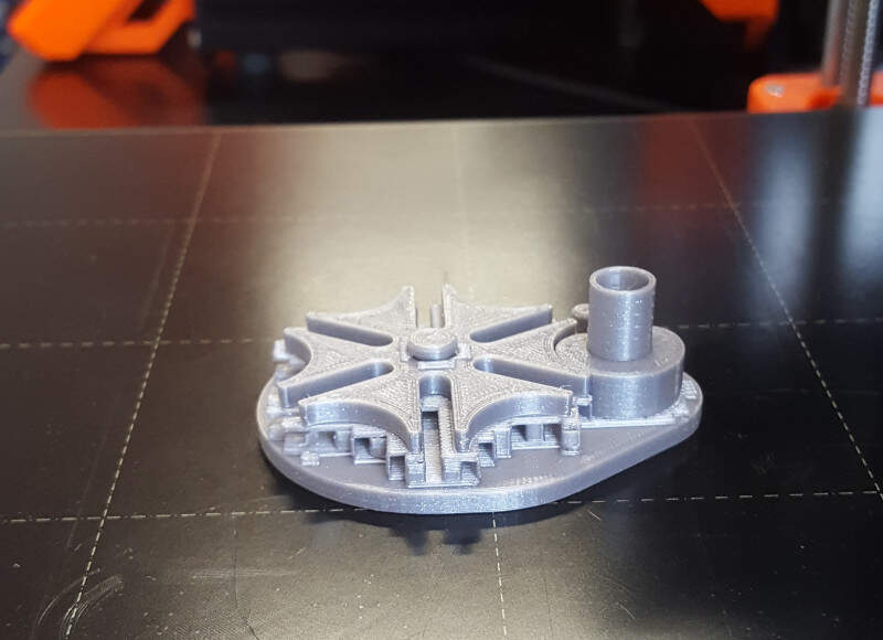
3D printing of the Geneva mechanism with support enforcers
After removing the support material the Geneva mechanism was finally working.
Animation of the Geneva mechanism
3D Scanning
For the second part of the assignment I decided to scan objects with different methods. The first method uses a 3D scanner with its dedicated software and the second method needs a camera and an open-source Photogrammetric Computer Vision Framework: Meshroon. With the first method I asked my team mate Quentin Bolsee to scan my bust. With the second method I scanned a small object (a cactus) and a large object (a Bas-relief of the Pergamon Museum, Berlin).
Software
Here is the list of the software used to 3D scan the objects:
Tools
Here is the list of the tools needed to 3D scan an object:
- A 3D scanner (first method)
- A camera (second method): I used my Samsung Galaxy S6 camera.
Work Flow
My bust - Scan with a 3D scanner
With this method nothing is really complicated. Download and install the software (Reboot your computer if needed). Plug the USB cable of the 3D scanner in your computer and start to scan the object. In less than 10 minutes the job was done and the program provided me a .OBJ file containing the mesh and a .MTL file with two .PNG pictures for the texture.
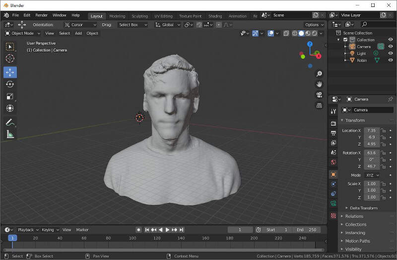
3D scanning of my bust without texture
As a result the mesh of my bust seems good but with the texture I feel a little bit creepy. I let you judge by yourself.
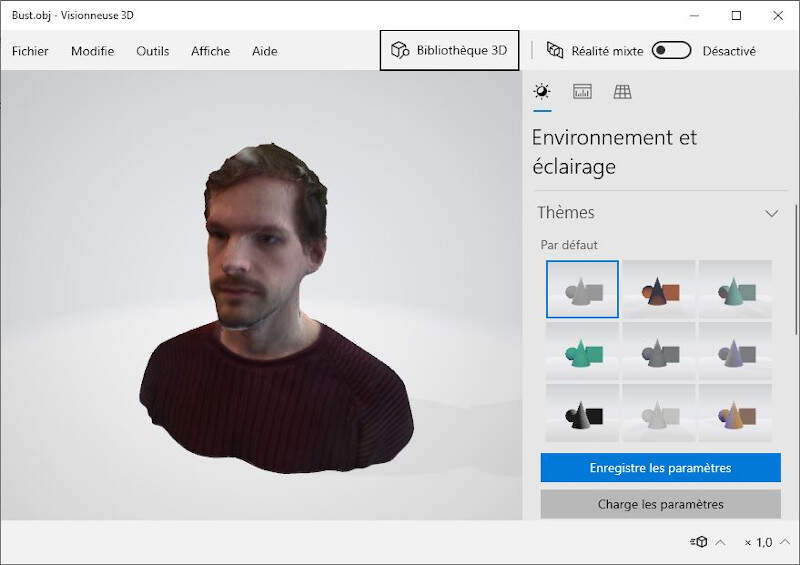
3D scanning of my bust with a texture
A cactus - Scan with a camera
For 3D scanning the cactus I placed it on a table beneath a lamp to have a constant exposure to light. I took 77 pictures of it with my Samsung Galaxy S6 camera and I fed them into Meshroom. It gave me a pretty good 3D scanning of the cactus and it even reconstructed a part of my apartment. I made a little bit of cleaning with blender as I was not really enthusiastic to show my living room to the entire web. Hereinafter is the picture of the cactus with its texture.
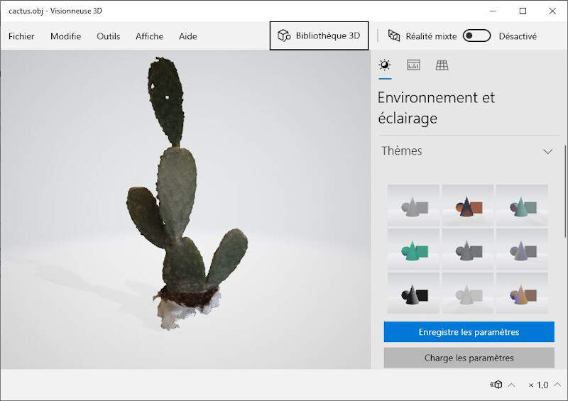
3D scanning of a cactus
A Bas-relief from Nineveh - Scan with a camera
For 3D scanning the Bas-relief from Nineveh I first tried to feed Meshroom with 144 pictures. It took a long time to process the images and it finally crashed my computer. I tried a second time with the same result. Therefore I decided to use Meshroom in Google Colab. As the time to download the 144 pictures was too long I left that solution aside and I decided to use less pictures to compute the mesh. Among the 144 I kept 117 pictures, which is still a decent number according to the photogrammetry section of Prusa to have a good result with Meshroom.
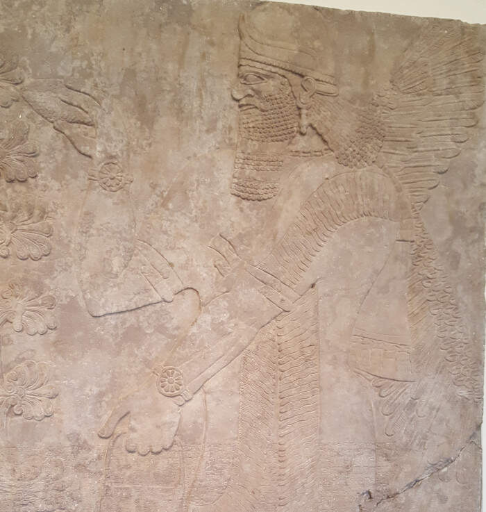
Bas-relief from Nineveh, in the Pergamon Museum, Berlin, Germany.
Babylonian civilization, 7th century BC.
This time Meshroom gave me a pretty good result. This result was expected since the light exposure in a museum was constant and I could be close from the Bas-relief enough to catch a lot of details with my smartphone camera.
Meshroom provides a bunch of files in different folders. The textured mesh .OBJ file can be found in the folder "MeshroomCache -> Texturing -> texturedMesh.obj". I used blender to open and edit it.
In Blender I first made a little bit of cleaning with the edit mode to keep only the stones. Then I selected the surface and used the function "extrude" to give it some thickness. Finally I added a wall and exported the files in .OBJ and .STL formats.
Hereinafter is a picture of the result with no texturing. I am very impressed by the quality of the details as the original bas-relief has very small depth variations.
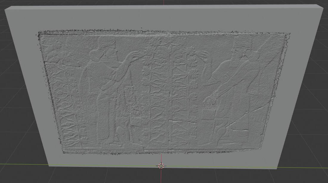
3D scanning of the bas-relief without texture
When the texture is added the result is also stunning.
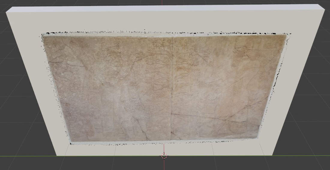
3D scanning of the bas-relief with texture
References
- PLA smoothing with chloroform
- Influence of the extrusion width on 3D printings
- Flexi structures to print on Thingiverse
- 3D printing and mesh analysis on Blender
Files
Since some files are larger than 5 Mo I was not able to share them on GitLab. As a consequence the following ZIP files are available on Google Drive.