Week 10 - Input devices
This week was dedicated to input devices. The main objective of this week was to be able to program a microcontroller in such a way that it could read data from a sensor. During this week we explored many sensors.
FAB ACADEMY 2020 source
20200325 Input Devices from Academany on Vimeo.
My Assignment
This week assignment consisted in measuring something by adding a sensor to a microcontroller board. Because of containment due to COVID19 it was not mandatory to necessarily design a new board for sensors measurements and it was allowed to use commercially available boards such as Arduino's. As a consequence I had a look to my electronic equipment I bought several years ago and I found an Arduino UNO (with the original ATMega328P), an Arduino LEONARDO (with the ATMega32U4) and several sensors such as a sonar distance sensor (HC-SR04), a water sensor, a proximity sensor and a strain gage. During WEEK 7 I also produced a board controlled by a ATSAMD11C14A microcontroller that provides five GPIOs. However one complication that might let me put that board aside is that the ATSAMD11C microcontroller logic works with 3.3V.
Please follow this link to know about the group assignment.
HC-SR04 sonar | programming
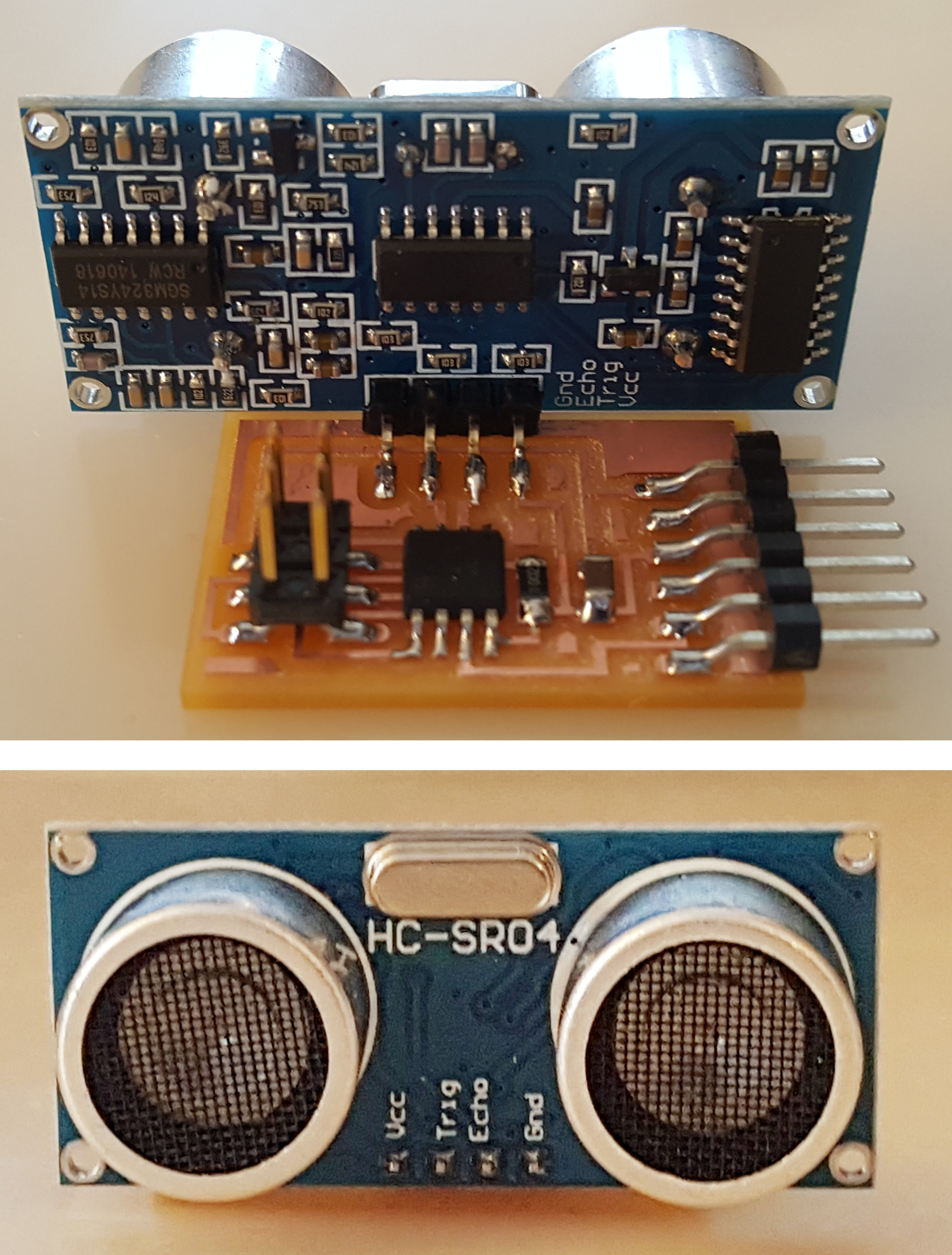
First I decided to focus on the sonar distance sensor and to have a look on its datasheet to know, among other things, its supply voltage. As the HC-SR04 sonar is a very common sensor its datasheet was easily found. Its supply voltage is 5V. Therefore I decided to first use an Arduino to make the acquisition of the signals than I'll find a solution to be able to read it with my own board.

Ultrasonic Sensor | HC-SR04
To know about how to connect it to any PCB and how to program it I also looked at different sources:
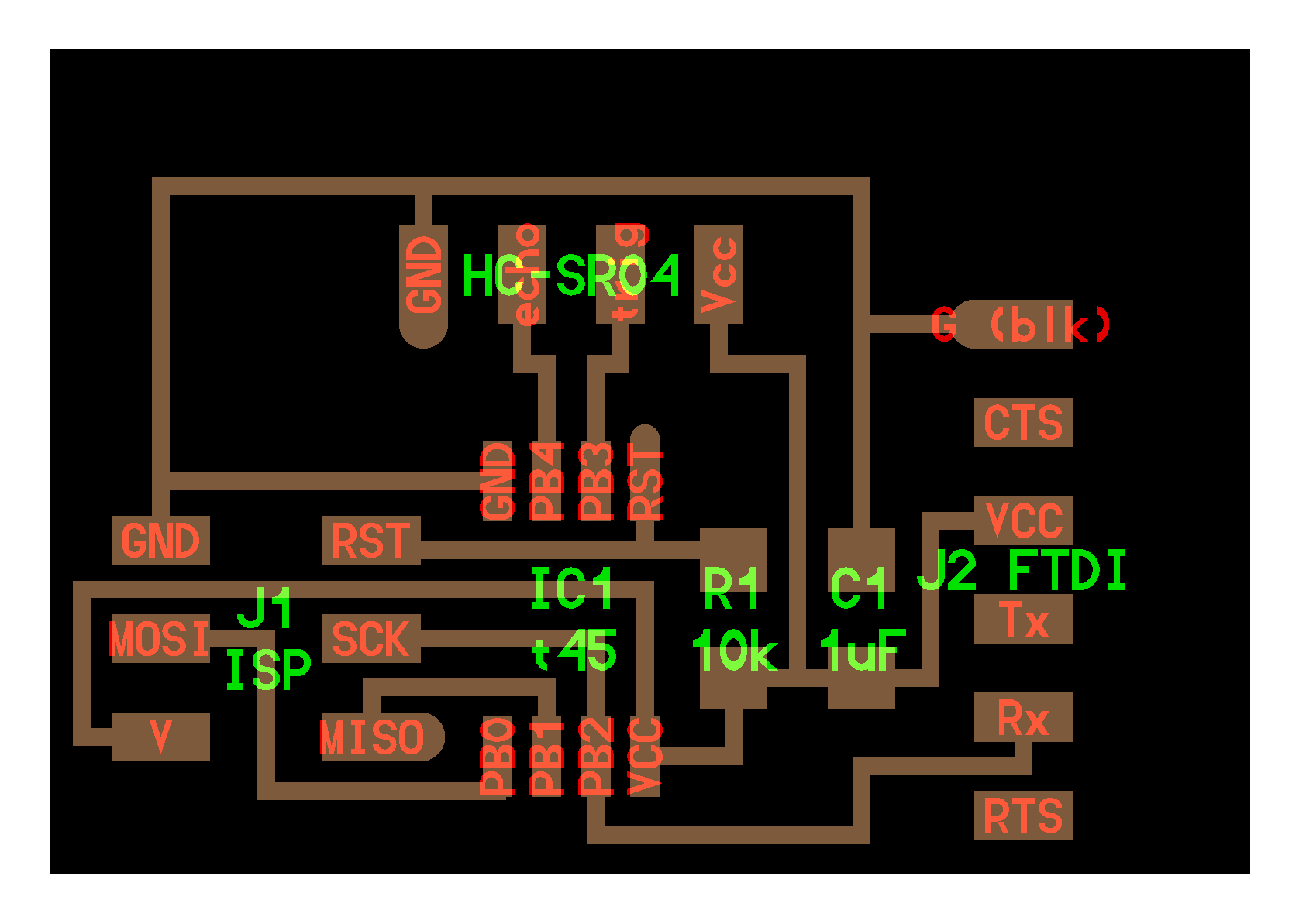
- The board and components available on the FabAcademy website. The example board uses a ATtiny45 that is able to work with a 5V logic. The communication is made through a serial port that allows the sensors to be powered and to send its signal through this peripheral. The ISP connector is used to program the ATtiny45. Two codes are also provided: a C code and python code.
- A nice tutorial in French that provides already an Arduino code with details about the programming.
Starting with the C code
First I started to read the C code provided by Neil. The slides about C programming and the wikipedia page about Operators in C and C++ helped me a lot to understand it.
The two first lines begin with the #include statement used to include in the following code two libraries that someone else wrote. As an example, the avr/io.h library happens to define DDRB, PORTB, PB2, PB3, PB4, PINB, CLKPR, TCNT0, TIFR, TCCR0B, TOV0 and CS00, variables that will be used later in the code, but it also defines much more variables.
  #include <avr/io.h>
  #include <util/delay.h>
Afterwards the statement #define gives a name to a constant value before the program is compiled. Defined constants won’t take up any program memory space on the chip. The compiler will replace references to these constants with the defined value at compile time, i.e. for the following syntax #define output(directions,pin) (directions |= pin) all variables with the name output(directions,pin) will be replaced in the code by (directions |=pin). This is done to simply write the easier to remember output(directions,pin).
  #define output(directions,pin) (directions |= pin) // set port direction for output
  #define set(port,pin) (port |= pin) // set port pin
  #define clear(port,pin) (port &= (~pin)) // clear port pin
  #define pin_test(pins,pin) (pins & pin) // test for port pin
  #define bit_test(byte,bit) (byte & (1 << bit)) // test for bit set
  #define bit_delay_time 102 // bit delay for 9600 with overhead
  #define bit_delay() _delay_us(bit_delay_time) // RS232 bit delay
  #define half_bit_delay() _delay_us(bit_delay_time/2) // RS232 half bit delay
  #define char_delay() _delay_ms(10) // char delay
Let's also have a look on the |= and &= ~ operators. a |= b means a = a | b and a &= ~b means a = a & ~b where ~ is the Bitwise NOT operator, & is the Bitwise AND operator and | is the Bitwise OR operator.
In the following #define statements PORTB, DDRB, PB2, PB3, PINB and PB4 are defined by the avr/io.h library. For example the echo_pin statement will be replaced by (1 >> PB4) but what does it mean? The >> operator is the Bitwise left shift assignment operator i.e. for the following statement 1 >> 8 one will be shifted 8 times on the left with the previous being replaced by zero. In this case the result will be 0b100000000. Note that on the board ports PB4, PB3 and PB2 are respectively connected to echo, trig and Rx which is completely coherent with the following variable declarations.
  #define serial_port PORTB
  #define serial_direction DDRB
  #define serial_pin_out (1 << PB2)
  #define trigger_port PORTB
  #define trigger_direction DDRB
  #define trigger_pin (1 << PB3)
  #define echo_pins PINB
  #define echo_direction DDRB
  #define echo_pin (1 << PB4)

  #define timeout 255
The following section of the code defines a function called put_char. This function happens to be responsible for serial communication. The void statement before the name of the function means that the function returns nothing. Note that there is a * in front of port. This * means that we are not interested by the value of port but we are by the value at the address indicated by the pointer port.
  void put_char(volatile unsigned char *port, unsigned char pin, char txchar) {
     //
     // send character in txchar on port pin
     //    assumes line driver (inverts bits)
     //
     // start bit
     //
     clear(*port,pin);
     bit_delay();
     //
     // unrolled loop to write data bits
     //
     if bit_test(txchar,0)
        set(*port,pin);
     else
        clear(*port,pin);
     bit_delay();
     if bit_test(txchar,1)
        set(*port,pin);
     else
        clear(*port,pin);
     bit_delay();
     if bit_test(txchar,2)
        set(*port,pin);
     else
        clear(*port,pin);
     bit_delay();
     if bit_test(txchar,3)
        set(*port,pin);
     else
        clear(*port,pin);
     bit_delay();
     if bit_test(txchar,4)
        set(*port,pin);
     else
        clear(*port,pin);
     bit_delay();
     if bit_test(txchar,5)
        set(*port,pin);
     else
        clear(*port,pin);
     bit_delay();
     if bit_test(txchar,6)
        set(*port,pin);
     else
        clear(*port,pin);
     bit_delay();
     if bit_test(txchar,7)
        set(*port,pin);
     else
        clear(*port,pin);
     bit_delay();
     //
     // stop bit
     //
     set(*port,pin);
     bit_delay();
     //
     // char delay
     //
     bit_delay();
     }
main is the name of the main function. The first part of that function declares some variables, initializes the output pins and sets the clock divider, and the second part (starting with while(1)) defines the main loop.
  int main(void) {
     //
     // main
     //
     static unsigned char high,low;
     //
     // set clock divider to /1
     //
     CLKPR = (1 << CLKPCE);
     CLKPR = (0 << CLKPS3) | (0 << CLKPS2) | (0 << CLKPS1) | (0 << CLKPS0);
     //
     // initialize output pins
     //
     set(serial_port,serial_pin_out);
     output(serial_direction,serial_pin_out);
     clear(trigger_port,trigger_pin);
     output(trigger_direction,trigger_pin);
     //
     // start counter
     //
     TCCR0B |= (1 << CS00); // prescale /1
     //
     // main loop
     //
     while (1) {
        SOME CODE
        }
     }
Here we only focus on the main loop code. The put_char(&serial_port,serial_pin_out,1); statement will put the char 1 on the serial port. Note that in front of the serial_port variable there is a &. This & operator means that we are interested by the address of the serial_port variable and not by its value.
     while (1) {
        //
        // trigger pulse
        //
        set(trigger_port,trigger_pin);
        _delay_us(10);
        clear(trigger_port,trigger_pin);
        //
        // wait for echo rising edge
        //
        high = 0;
        TCNT0 = 0;
        TIFR |= (1 << TOV0);
        while (1) {
           if ((echo_pins & echo_pin) != 0) // check for rising edge
              break;
           if ((TIFR & (1 << TOV0)) != 0) { // check for counter overflow
              high += 1;
              if (high == timeout)
                 break;
              TIFR |= (1 << TOV0);
              }
           }
        //
        // rising edge found, wait for falling edge
        //
        high = 0;
        TCNT0 = 0;
        TIFR |= (1 << TOV0);
        while (1) {
           if ((echo_pins & echo_pin) == 0) { // check for falling edge
              low = TCNT0;
              break;
              }
           if ((TIFR & (1 << TOV0)) != 0) { // check for counter overflow
              high += 1;
              if (high == timeout)
                 break;
              TIFR |= (1 << TOV0);
              }
           }
        //
        // send count with framing
        //
        put_char(&serial_port,serial_pin_out,1);
        put_char(&serial_port,serial_pin_out,2);
        put_char(&serial_port,serial_pin_out,3);
        put_char(&serial_port,serial_pin_out,4);
        put_char(&serial_port,serial_pin_out,low);
        put_char(&serial_port,serial_pin_out,high);
        //
        // delay before next cycle
        //
        _delay_ms(10);
        }
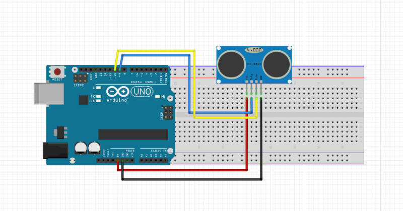
Once the code understood I modified it to make an Arduino code. First I removed the #include statements as Arduino handles that by itself. Then I put the first part of the void main() function in the void setup() part of the Arduino code. As the while (1) part of the main function is the main loop, I moved it inside the void loop() function of the Arduino file. I tried to keep the put_char function but as I was receiving nothing on the serial port while using it I changed the code and used the Arduino serial function. Finally, I checked on the schematic of the Arduino Leonardo to know how to connect the trigger and echo pins of the sonar.
- Trig -> PB5 -> IO9
- Echo -> PB6 -> IO10
Here is how I cabled the Arduino Leonardo to the sensor.
I finally came up with the following code.
  #define output(directions,pin) (directions |= pin) // set port direction for output
  #define set(port,pin) (port |= pin) // set port pin
  #define clear(port,pin) (port &= (~pin)) // clear port pin
  #define pin_test(pins,pin) (pins & pin) // test for port pin
  #define bit_test(byte,bit) (byte & (1 << bit)) // test for bit set
  #define bit_delay_time 102 // bit delay for 9600 with overhead
  #define bit_delay() _delay_us(bit_delay_time) // RS232 bit delay
  #define half_bit_delay() _delay_us(bit_delay_time/2) // RS232 half bit delay
  #define char_delay() _delay_ms(10) // char delay

  #define trigger_port PORTB
  #define trigger_direction DDRB
  #define trigger_pin (1 << PB5)
  #define echo_pins PINB
  #define echo_direction DDRB
  #define echo_pin (1 << PB6)

  #define timeout 255

  int time_count=0;


  void setup() {


     //
     // set clock divider to /1
     //
     CLKPR = (1 << CLKPCE);
     CLKPR = (0 << CLKPS3) | (0 << CLKPS2) | (0 << CLKPS1) | (0 << CLKPS0);
     //
     // initialize output pins
     //
     Serial.begin(9600);

     clear(trigger_port,trigger_pin);
     output(trigger_direction,trigger_pin);
     //
     // start counter
     //
     TCCR0B |= (1 << CS00); // prescale /1

  }

  void loop() {

        static unsigned char high,low;
        // trigger pulse
        //
        set(trigger_port,trigger_pin);
        _delay_us(10);
        clear(trigger_port,trigger_pin);
        //
        // wait for echo rising edge
        //
        high = 0;
        TCNT0 = 0;
        TIFR0 |= (1 << TOV0);
        while (1) {
           if ((echo_pins & echo_pin) != 0) // check for rising edge
              break;
           if ((TIFR0 & (1 << TOV0)) != 0) { // check for counter overflow
              high += 1;
              if (high == timeout)
                 break;
              TIFR0 |= (1 << TOV0);
              }
           }
        //
        // rising edge found, wait for falling edge
        //
        high = 0;
        TCNT0 = 0;
        TIFR0 |= (1 << TOV0);
        while (1) {
           if ((echo_pins & echo_pin) == 0) { // check for falling edge
              low = TCNT0;
              break;
              }
           if ((TIFR0 & (1 << TOV0)) != 0) { // check for counter overflow
              high += 1;
              if (high == timeout)
                 break;
              TIFR0 |= (1 << TOV0);
              }
           }
        //
        // send count with framing
        //
        time_count++;
        Serial.print("Time: ");
        Serial.println(time_count);

        Serial.print("LOW: ");
        Serial.println(low);

        Serial.print("HIGH: ");
        Serial.println(high);
        //
        // delay before next cycle
        //
        _delay_ms(1000);

  }
Here are the results I got on the Arduino Serial Monitor with a pause of 1 second between each measurements.
Arduino Serial Monitor
At that point I had no clue if my data was indeed providing the right distance between the object and the sensor but at least I had some values. The next step was to use the hello.HC-SR04.py python script provided by Neil. It uses pySerial, a Python module to access the serial port, and Tkinter, a Python GUI, to let you see the distance evolution in real time in a user-friendly way. This will be explained in the section about HC-SR04 sonar | Python GUI but for now let me continue with the programming with a different approach using a sample Arduino code for the HC-SR04 sonar.
Starting with the HC-SR04 Arduino sample code
My source for this section is the nice French tutorial providing a Arduino Code. The code provided is right below. I'll explain it and adapt it.
  /*
   * Code d'exemple pour un capteur à ultrasons HC-SR04.
   */

  /* Constantes pour les broches */
  const byte TRIGGER_PIN = 2; // Broche TRIGGER
  const byte ECHO_PIN = 3;    // Broche ECHO

  /* Constantes pour le timeout */
  const unsigned long MEASURE_TIMEOUT = 25000UL; // 25ms = ~8m à 340m/s

  /* Vitesse du son dans l'air en mm/us */
  const float SOUND_SPEED = 340.0 / 1000;

  /** Fonction setup() */
  void setup() {

    /* Initialise le port série */
    Serial.begin(115200);

    /* Initialise les broches */
    pinMode(TRIGGER_PIN, OUTPUT);
    digitalWrite(TRIGGER_PIN, LOW); // La broche TRIGGER doit être à LOW au repos
    pinMode(ECHO_PIN, INPUT);
  }

  /** Fonction loop() */
  void loop() {

    /* 1. Lance une mesure de distance en envoyant une impulsion HIGH de 10µs sur la broche TRIGGER */
    digitalWrite(TRIGGER_PIN, HIGH);
    delayMicroseconds(10);
    digitalWrite(TRIGGER_PIN, LOW);

    /* 2. Mesure le temps entre l'envoi de l'impulsion ultrasonique et son écho (si il existe) */
    long measure = pulseIn(ECHO_PIN, HIGH, MEASURE_TIMEOUT);

    /* 3. Calcul la distance à partir du temps mesuré */
    float distance_mm = measure / 2.0 * SOUND_SPEED;

    /* Affiche les résultats en mm, cm et m */
    Serial.print(F("Distance: "));
    Serial.print(distance_mm);
    Serial.print(F("mm ("));
    Serial.print(distance_mm / 10.0, 2);
    Serial.print(F("cm, "));
    Serial.print(distance_mm / 1000.0, 2);
    Serial.println(F("m)"));

    /* Délai d'attente pour éviter d'afficher trop de résultats à la seconde */
    delay(500);
  }
First I changed the pins constant since in my case the trigger pin is connected to PIN 9 of the Arduino and the echo pin is connected to PIN 10. The timeout constant is time for which we consider that there is no obstacle and as a consequence no possible measurement because no echo is coming back. The timeout constant was chosen equal to 25ms = 25000UL. If we consider sound speed equals 340m/s, 25ms is equivalent to a maximum distance measurement of 4 meters back and forth. It might be interesting to modify the timeout constant later to increase the measurement capabilities of the sensor. For now, we will keep it like this.
  /*
   * Sample code for the HC-SR04 ultrasonic sensor.
   */

  /* PIN constants */
  const byte TRIGGER_PIN = 9; // TRIGGER PIN
  const byte ECHO_PIN = 10;    // ECHO PIN

  /* Timeout constant*/
  const unsigned long MEASURE_TIMEOUT = 25000UL; // 25ms = ~8m à 340m/s

  /* Sound speed in mm/us */
  const float SOUND_SPEED = 340.0 / 1000;
In the setup() function I only changed the baud rate to 9600. The TRIGGER_PIN is an output initialized as low at the beginning. The ECHO_PIN is an input.
  /** Fonction setup() */
  void setup() {

    /* Initialise le port série */
    Serial.begin(115200);

    /* Initialise les broches */
    pinMode(TRIGGER_PIN, OUTPUT);
    digitalWrite(TRIGGER_PIN, LOW); // La broche TRIGGER doit être à LOW au repos
    pinMode(ECHO_PIN, INPUT);
  }
In the loop() function I changed the data sent through serial communication and the time delay (100 ms). In that loop the TRIGGER_PIN is first set to high to send a sound for 10µs then TRIGGER_PIN goes back to low. Afterwards the pulseIn() function tries to detect a pulse on ECHO_PIN and returns the length of the pulse in microseconds or gives up and returns 0 if no complete pulse was received within the timeout. After we compute the distance from the measured time. The formula can be find in the sensor datasheet but is pretty straightforward: the distance is the time the sound needs to travel back and forth divided by two and multiplied by sound speed. After that we send a synchronizing sequence (1, 2, 3, 4) on the serial port followed by the distance in cm.
    /** Fonction loop() */
    void loop() {

      /* 1. Run a distance measurement by sending a HIGH impulse of 10µs on TRIGGER pin */
      digitalWrite(TRIGGER_PIN, HIGH);
      delayMicroseconds(10);
      digitalWrite(TRIGGER_PIN, LOW);

      /* 2. Measure time between the HIGH ultrasonic impulse sending and its echo (if it exists) */
      long measure = pulseIn(ECHO_PIN, HIGH, MEASURE_TIMEOUT);

      /* 3. Compute the distance from the measured time */
      float distance_mm = measure / 2.0 * SOUND_SPEED;

      /* Serial communication */
      Serial.write(1);
      Serial.write(2);
      Serial.write(3);
      Serial.write(4);
      Serial.write(distance_mm / 10.0);

      /* Delay between each measurements */
      delay(100);
    }
Hereinafter is the full code used to measure the distance. With this code I was finally able to know if the measured distance was corresponding to the true distance. And it worked!!
  /*
   * Code d'exemple pour un capteur à ultrasons HC-SR04.
   */

  /* Constantes pour les broches */
  const byte TRIGGER_PIN = 9; // Broche TRIGGER
  const byte ECHO_PIN = 10;    // Broche ECHO

  /* Constantes pour le timeout */
  const unsigned long MEASURE_TIMEOUT = 25000UL; // 25ms = ~8m à 340m/s

  /* Vitesse du son dans l'air en mm/us */
  const float SOUND_SPEED = 340.0 / 1000;

  /** Fonction setup() */
  void setup() {

    /* Initialise le port série */
    Serial.begin(115200);

    /* Initialise les broches */
    pinMode(TRIGGER_PIN, OUTPUT);
    digitalWrite(TRIGGER_PIN, LOW); // La broche TRIGGER doit être à LOW au repos
    pinMode(ECHO_PIN, INPUT);
  }

  /** Fonction loop() */
  void loop() {

    /* 1. Lance une mesure de distance en envoyant une impulsion HIGH de 10µs sur la broche TRIGGER */
    digitalWrite(TRIGGER_PIN, HIGH);
    delayMicroseconds(10);
    digitalWrite(TRIGGER_PIN, LOW);

    /* 2. Mesure le temps entre l'envoi de l'impulsion ultrasonique et son écho (si il existe) */
    long measure = pulseIn(ECHO_PIN, HIGH, MEASURE_TIMEOUT);

    /* 3. Calcul la distance à partir du temps mesuré */
    float distance_mm = measure / 2.0 * SOUND_SPEED;

    /* Envoi sur le port serie */
    Serial.write(1);
    Serial.write(2);
    Serial.write(3);
    Serial.write(4);
    Serial.write(distance_mm / 10.0);

    /* Délai d'attente pour éviter d'afficher trop de résultats à la seconde */
    delay(100);
  }
After that I also made another version of this code where I'm only sending the time measured between the HIGH ultrasonic impulse sending and its echo through serial communication. This version was interesting to do because I was not able to properly send this value. The reason was that the measured time had a value higher than 255 and a byte of 8 binary bits can represent 28 = 256 numbers: 0 - 255. I found a solution for that issue on Arduino's forum. I had to split the number in two different bytes: one LSB and one MSB that I respectively named "low" and "high". In the equation low = measure % 256, % is the modulo operator. The result of the equation high = measure / 256 is an integer. Finally measure = high * 256 + low. This helped me a lot to understand what was done in the original hello.HC-SR04.py python script provided by Neil.
  /*
   * Code d'exemple pour un capteur à ultrasons HC-SR04.
   */

  /* Constantes pour les broches */
  const byte TRIGGER_PIN = 9; // Broche TRIGGER
  const byte ECHO_PIN = 10;    // Broche ECHO

  /* Constantes pour le timeout */
  const unsigned long MEASURE_TIMEOUT = 25000UL; // 25ms = ~8m à 340m/s

  /* Vitesse du son dans l'air en mm/us */
  const float SOUND_SPEED = 340.0 / 1000;

  /** Fonction setup() */
  void setup() {

    /* Initialise le port série */
    Serial.begin(115200);

    /* Initialise les broches */
    pinMode(TRIGGER_PIN, OUTPUT);
    digitalWrite(TRIGGER_PIN, LOW); // La broche TRIGGER doit être à LOW au repos
    pinMode(ECHO_PIN, INPUT);
  }

  /** Fonction loop() */
  void loop() {

    /* 1. Lance une mesure de distance en envoyant une impulsion HIGH de 10µs sur la broche TRIGGER */
    digitalWrite(TRIGGER_PIN, HIGH);
    delayMicroseconds(10);
    digitalWrite(TRIGGER_PIN, LOW);

    /* 2. Mesure le temps entre l'envoi de l'impulsion ultrasonique et son écho (si il existe) */
    long measure = pulseIn(ECHO_PIN, HIGH, MEASURE_TIMEOUT);

    /* Envoi sur le port serie */
    Serial.write(1);
    Serial.write(2);
    Serial.write(3);
    Serial.write(4);
    Serial.write(measure % 256); //low
    Serial.write(measure / 256); //high


    /* Délai d'attente pour éviter d'afficher trop de résultats à la seconde */
    delay(100);
  }
HC-SR04 sonar | Python GUI
Obviously this section required Python installation and pySerial installation, a python module for serial communication. As Python was already installed on my computer I only had to worry about pySerial installation. After the installation I tried to understand how worked the original hello.HC-SR04.py python script provided by Neil and I had to debug it.
To install pySerial on Windows I opened a command prompt as administrator and I wrote the command pip install pyserial.
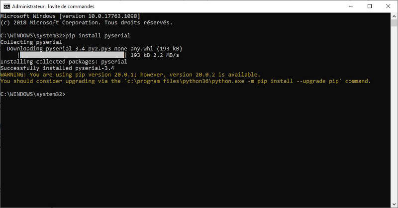
Command prompt - pySerial installation
Then I opened the hello.HC-SR04.py file in ATOM. Hereinafter I explain the main parts of this code and adapt it if necessary.
First we import two libraries. serial is the library that we had just installed. Tkinter is a GUI python module. Depending on the python version, Tkinter sometimes comes with an uppercase or lowercase letter at the beginning. After three variables are declared WINDOW, filt and eps. I also had to import sys so I added it right after import serial.
  from Tkinter import *
  import serial
  import sys

  WINDOW = 600 # window size
  filt = 0
  eps = 0.1
Then the idle(parent,canvas) function is defined. The while loop inside it is a synchronization loop. Once the sequence (1, 2, 3 , 4) is found we read "low" and then "high". Then we compute a value with the formula seen in the above section. Then a filter is added on that value and finally we compute cm, the distance in centimeters, thanks to a formula that can be found in the sensor datasheet. Then we create a variable x that will be used to size an item in the main window of the GUI.
 def idle(parent,canvas):
     global filt,eps
     #
     # idle routine
     #
     byte2 = 0
     byte3 = 0
     byte4 = 0
     ser.flush()
     while 1:
        #
        # find framing
        #
        byte1 = byte2
        byte2 = byte3
        byte3 = byte4
        byte4 = ord(ser.read())
        if ((byte1 == 1) & (byte2 == 2) & (byte3 == 3) & (byte4 == 4)):
           break
     low = ord(ser.read())
     high = ord(ser.read())
     value = (256*high + low)
     filt = (1-eps)*filt+eps*value
     us = filt/8.0 # 8 MHz counter
     cm = us/58.0
     x = int(.2*WINDOW + (.9-.2)*WINDOW*cm/50)
     canvas.itemconfigure("text",text="%.0f cm"%cm)
     canvas.coords('rect1',.2*WINDOW,.05*WINDOW,x,.2*WINDOW)
     canvas.coords('rect2',x,.05*WINDOW,.9*WINDOW,.2*WINDOW)
     canvas.update()
     parent.after_idle(idle,parent,canvas)
The following codes lines check the command line arguments. Indeed when we will run the code we will need to write python hello.HC-SR04.py COM10 in the command prompt to specify the name of the USB port used for serial communication (in this example COM10). If the number of arguments is different from 2, the program will print a reminder in the command prompt.
  #
  #  check command line arguments
  #
  if (len(sys.argv) != 2):
     print "command line: hello.HC-SR04.py serial_port"
     sys.exit()
  port = sys.argv[1]
Here we create a variable ser to set the serial communication by passing it the serial port and the baud rate.
  #
  # open serial port
  #
  ser = serial.Serial(port,9600)
  ser.setDTR()
The rest of the code defines the title of the main window, the command q to quit the GUI and the position of items such as text or rectangles.
  #
  # set up GUI
  #
  root = Tk()
  root.title('hello.HC-SR04.py (q to exit)')
  root.bind('q','exit')
  canvas = Canvas(root, width=WINDOW, height=.25*WINDOW, background='white')
  canvas.create_text(.1*WINDOW,.125*WINDOW,text=".33",font=("Helvetica", 24),tags="text",fill="#0000b0")
  canvas.create_rectangle(.2*WINDOW,.05*WINDOW,.3*WINDOW,.2*WINDOW, tags='rect1', fill='#b00000')
  canvas.create_rectangle(.3*WINDOW,.05*WINDOW,.9*WINDOW,.2*WINDOW, tags='rect2', fill='#0000b0')
  canvas.pack()
  #
  # start idle loop
  #
  root.after(100,idle,root,canvas)
  root.mainloop()
It is now time to test the code. Go the folder where the file is located and type cmd in the location bar. A command prompt pops up. In the command prompt write python
Python GUI for measurements from an ultrasonic sensor
HC-SR04 sonar | HTML and JavaScript GUI
For this section I used the hello.mag.45.html and the hello.mag.45.js provided by Neil for a Hall-Effect sensor. Later I would modify these codes such that they fit to my distance sensor. The execution of the codes required several software installations: Node.js and npm
Node.js and npm installations
To install Node.js just download it and launch the installation file. After in the command prompt write npm install npm -g. After that check the Node.js and npm versions by writing successively node -v and npm -v. Hereinafter is the result.
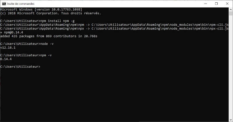
Command prompt - npm installation and version check
Now we were sure that Node.js and npm are installed. It was time to run the JavaScript by writing node hello.mag.45.js. Unfortunately I received the following error message: Error: Cannot find module 'serialport'. As a consequence I installed the serialport module by executing the command: npm install serialport.
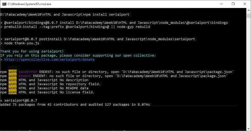
Command prompt - serialport installation
After that I tried again to execute the JavaScript and I received another error message: Error: Cannot find module 'ws'. To solve that I executed the command: npm install ws
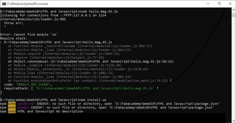
Command prompt - ws installation
After that modification an other error appeared.
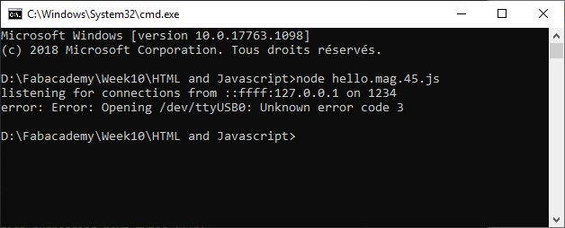
Command prompt - Error: Opening /dev/ttyUSB0: Unknown error code 3
To solve that issue I changed var serial_port = "/dev/ttyUSB0" by var serial_port = "COM10" in the JavaScript.
Finally after all these modifications the command node hello.mag.45.js was executed successfully.
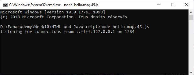
Command prompt - Successful execution
Let's now have a look on the modification of the JavaScript to adapt it to the ultrasonic sensor.
Modification of the JavaScript
Just like in the python file there is a synchronization sequence. The sequence (1, 2, 3, 4) is followed by "low" and "high" hence the statement measure = (byte5 + 256*byte6) if (byte1 == 1) & (byte2 == 2) & (byte3 == 3) & (byte4 == 4). The rest of the code aims at computing the distance value in centimeters.
  parser.on('data',function(data) {
     byte1 = byte2
     byte2 = byte3
     byte3 = byte4
     byte4 = byte5
     byte5 = byte6
     byte6 = data[0]
     if ((byte1 == 1) & (byte2 == 2) & (byte3 == 3) & (byte4 == 4)) {
        measure = (byte5 + 256*byte6)
        filt = (1-eps)*filt+eps*measure
        distance_mm = filt / 2.0 * sound_speed
        value=distance_mm/10
        }
     })
To be able to compute the distance value I also had to declare upper some constants.
  var sound_speed = 340.0 / 1000
  var eps = 0.1
  var filt = 0
  var distance_mm = 0
Hereinafter is the full code.
  //
  // hello.mag.45.js
  //
  // read and send magnetic field
  //    npm install ws and serialport
  //
  // Neil Gershenfeld
  // (c) Massachusetts Institute of Technology 2014
  //
  // This work may be reproduced, modified, distributed, performed, and
  // displayed for any purpose, but must acknowledge the fab modules
  // project. Copyright is retained and must be preserved. The work is
  // provided as is; no warranty is provided, and users accept all
  // liability.
  //
  var server_port = '1234'
  var client_address = '::ffff:127.0.0.1'
  //var serial_port = "/dev/ttyUSB0"
  var serial_port = "COM10"
  var baud = 9600
  var sound_speed = 340.0 / 1000
  var eps = 0.1
  var filt = 0
  var distance_mm = 0
  //
  // open serial port
  //
  var SerialPort = require("serialport")
  var sp = new SerialPort(serial_port,{baudRate:baud})
  sp.on('error',function(err) {
     console.log("error: "+err)
     process.exit(-1)
     })
  //
  // look for framing and then update field value
  //
  var byte2 = 0
  var byte3 = 0
  var byte4 = 0
  var byte5 = 0
  var byte6 = 0
  var value = 0
  var measure = 0
  var ByteLength = SerialPort.parsers.ByteLength
  var parser = sp.pipe(new ByteLength({length:1}));
  parser.on('data',function(data) {
     byte1 = byte2
     byte2 = byte3
     byte3 = byte4
     byte4 = byte5
     byte5 = byte6
     byte6 = data[0]
     if ((byte1 == 1) & (byte2 == 2) & (byte3 == 3) & (byte4 == 4)) {
        measure = (byte5 + 256*byte6)
        filt = (1-eps)*filt+eps*measure
        distance_mm = filt / 2.0 * sound_speed
        value=distance_mm/10
        }
     })
  //
  // wait for socket request and then send field value
  //
  console.log("listening for connections from "+client_address+" on "+server_port)
  var Server = require('ws').Server
  wss = new Server({port:server_port})
  wss.on('connection', function(ws) {
     if (ws._socket.remoteAddress != client_address) {
        console.log("error: client address "+ws._socket.remoteAddress+" doesn't match")
        return
        }
     console.log("connected to "+client_address+" on port "+server_port)
     ws.on('message', function(data) {
        ws.send(JSON.stringify(value.toFixed(1)))
        })
     })
The video provided by Neil also helped me a lot to understand what was the procedure to use the JavaScript in combination with the HTML file. First open the HTML file, then make sure the board is connected to the computer and execute the JavaScript. Finally refresh the HTML page. The following video presents the results.
JavaScript and HTML GUI for measurements from an ultrasonic sensor
What's remaining
Here is a list of what I still want to do.
- Find a solution to plug the sonar on my own board with 3.3V logic and code for it.
- Understand better the way the serial function works and how to adapt it.
- Understand better how the sonar function works.
- Look at the Arduino libraries and compares instructions. For example find out exactly how the
DigitalWritefunction works. Here is a link to a start of explanation very handy to know where to find the information. - Use ATMEL studio to code.
- Find and compare datasheets of ATtiny45, ATMega32U4 and ATSAMD1CC14A.
- Book about AVR programming and about ARM programming?
Files